Experimental Characterization of a Broadband Transmission-Line Cloak in Free Space
Abstract
The cloaking efficiency of a finite-size cylindrical transmission-line cloak operating in the X-band is verified with bistatic free space measurements. The cloak is designed and optimized with numerical full-wave simulations. The reduction of the total scattering width of a metal object, enabled by the cloak, is clearly observed from the bistatic free space measurements. The numerical and experimental results are compared resulting in good agreement with each other.
I Introduction
The transmission-line cloak concept has been recently introduced [1, 2] as an alternative to the transformation-optics [3, 4] and scattering cancellation approaches [5, 6]. Instead of utilizing anisotropic (and often resonant) metamaterials [4] or plasmonic materials [6], the transmission-line cloak enables the electromagnetic wave to smoothly travel through the cloaked object inside a volumetric network of transmission lines, resulting in a simple and cheap way to obtain broadband cloaking of objects with selected geometries. It should be emphasized that the transmission-line cloak can only “hide” objects that fit inside the volumetric network [2].
A clear distinction should be made between three-dimensional cloaks that can hide an object in free space and the so-called ground-plane cloaks that can be used to hide an object above a boundary [7, 8]. The ground-plane cloaks are eminently simpler to realize since the complexity of the material parameters is not so demanding as in cloaks that should hide a finite object in free space.
In this work we study a finite-size, three-dimensional transmission-line cloak that can hide a three-dimensional metallic object from electromagnetic waves in free space. The basic cloak geometry is known from previous results [2] and the dimensions of the cloak are here optimized for operation in the X-band (8 GHz – 12 GHz). The previous realizations of the cylindrical transmission-line cloak utilized a coupling layer made of widening metal strips to couple the electromagnetic waves between the free space and the volumetric transmission-line network. To simplify the cloak design and to enable more accurate and faster assembly of the structure, we have very recently introduced an alternative way of realizing the coupling layer by using solid conical metal discs [9] instead of strips. This makes both the design and manufacturing of the cloak simpler since the structure is more rigid and the coupling layer does not anymore bring a strong frequency dependence to the cloak operation [9].
In this paper we introduce the new cloak design and present numerical results for the ratio of the total scattering widths of cloaked and uncloaked objects. The cloak is manufactured and its operation is experimentally verified with an X-band bistatic measurement setup consisting of two antennas and a vector network analyzer (VNA). With this setup we can obtain experimentally the ratio of the total scattering widths that can then be compared to the numerical results. It is shown that both the numerical and experimental results demonstrate a broadband cloaking effect. Free space bistatic measurements conducted with a finite-size cloak are an important step toward a full characterization of practical electromagnetic cloaks, as the previously published experimental results considering total scattering from various cloaks have been conducted with parallel-plate waveguide setups [10, 11].
II Cloak Geometry
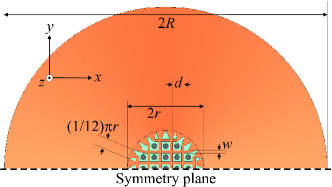
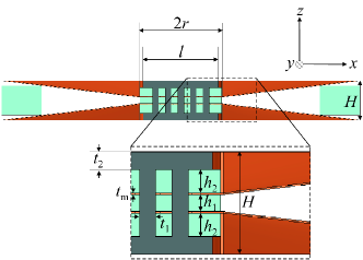
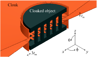
The present cloak geometry is a modification of the previously studied cylindrical transmission-line cloak [2]. The transition or coupling layer that couples the electromagnetic waves between a set of layered two-dimensional transmission-line networks and the surrounding free space, is composed of metal cones, as illustrated in Fig. 1. This coupling layer geometry has been studied numerically [9] and it was shown that, unlike in the previous designs utilizing gradually widening strip transmission lines [2], the outer diameter of the cone (i.e., the thickness of the transition layer) does not strongly affect the frequency of optimal cloaking. The coupling and therefore the cloaking performance are improved as the thickness of this layer increases [9]. For practical purposes we limit the thickness of these layers after obtaining a good level of cloaking so that the cloak does not become impractically large compared to the cloaked object.
The optimization of the cloak dimensions was carried out essentially by first directly scaling the dimensions of the previous structure [9], operating at frequencies around 3 GHz, so that the new operating frequency band occurs in X-band with the center of the cloaking band at 10 GHz. Then, taking into account material restrictions (the dielectric material used for insulation between metal parts was available only in certain specific thicknesses), some design parameters were fixed to appropriate values regarding manufacturing and assembly while the remaining few key parameters (e.g. the height of a single cloak layer ) were numerically optimized with ANSYS HFSS [12].
As illustrated in Fig. 1, the cloak consists of thin sheets of metal and a dielectric insulator (heights and ) that is used to separate the successive layers of transmission-line strips from each other and from the cloaked metal object. As shown in Fig. 1, the cloaked object is an array of long metal rods connected periodically to a set of thin metal discs. It should be emphasized that in principle there is no restriction on the geometry of the cloaked object (nor, for example, the number of rods), as long as it fits inside the volumetric transmission-line network [2]. As it is favourable to have the wavenumber of the transmission lines as close as possible to the wavenumber in free space [2], the dielectric is chosen to have low permittivity and low losses. Here we use Rohacell® 51 HF [13] with a relative permittivity of and loss tangent of 0.003.
| 2.1 mm | |
|---|---|
| 0.5 mm | |
| 1.1 mm | |
| 1.5 mm | |
| 6.6 mm | |
| 7 mm | |
| 30 mm | |
| 12.6 mm | |
| 0.1 mm | |
| 1 mm | |
| 1.15 mm |
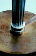
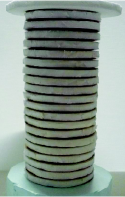
For practical reasons we do not employ solid metal cones in the structure, but instead thin metal sheets that are bent to the conical shape. To obtain the same response as with solid cones, we place a hollow metal cylinder (with thickness and outer radius , see Fig. 1b,c) around the cloaked object so that the inside volume of the cone is impenetrable to electromagnetic waves. Photographs of the structure are shown in Fig 2. The final, finite-size cloak consists of 20 layers of the structure of Fig. 1, resulting in the total height of mm mm for both the cloaked and uncloaked object. This height is much larger than the half-power width of the antenna pattern at the location of the object in the measurement setup (see the next section), which means that we can expect negligible reflections from the top and bottom of the cloak structure and we can assume that the structure scatters effectively in the -plane only.
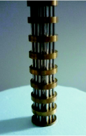
Since the metal cones are made of thin sheets, the final cloak structure is made mechanically more stable by adding cylindrical dielectric supports to the ends of the openings of the metal cones (illustrated in Fig. 1b and Fig. 2c). These dielectric supports are also made of the same Rohacell® material as above and have the height equal to 5 mm and the inner and outer radii of 23.5 mm and 30 mm, respectively. Although the effect of these support cylinders is expected to be very minor due to the low permittivity of the material, these cylinders are taken into account in the numerical simulations.
III Measurement Setup and Analysis
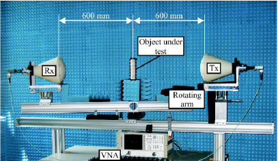
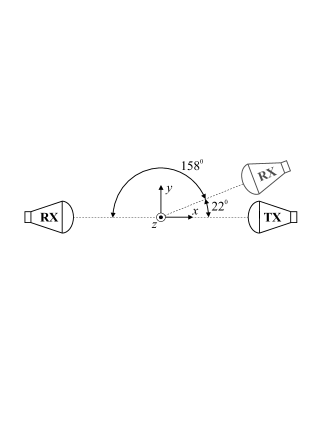
The measurement setup consists of two X-band antennas equipped with dielectric lenses that focus the electromagnetic energy on a focal spot (half-power width approximately 45 mm) between the antennas. The object under test is placed in this focus as shown in Fig. 3. The transmitting antenna (Tx) is stationary, whereas the receiving antenna (Rx) is placed on a rotating arm that can be moved around the measured object. The measured objects are symmetric with respect to the -plane, so that a bistatic measurement over the angular range from to is sufficient. However, due to large antenna dimensions, we are restricted to the angular range from to , as illustrated in Fig. 3b. The measurements are conducted with an angular step of and for each angle, the complex transmission coefficient () between the antennas is measured with a vector network analyzer (Agilent HP 8719D) in the frequency range 8.2 GHz – 12.4 GHz.
To characterize the total scattering width of an object, we need to know the angle-dependent scattered field . This can be obtained from the measured transmission results by subtracting the free space transmitted fields (transmission between the antennas without any scattering object in between):
| (1) |
where is the transmission coefficient between the Tx and Rx antennas, and “O” and “FS” refer to “object” and “free space”, respectively. The normalized total scattering width , i.e., the total scattering width of the cloaked object normalized by the total scattering width of the uncloaked object, can be obtained by integrating the scattered field intensities:
| (2) |
In addition to the bistatic measurements used in (1), one can also make a monostatic measurement with only one antenna in order to obtain the scattered field at . This is done simply by measuring the reflection coefficient () of the Tx antenna and equating the result to the scattered field:
| (3) |
This quantity is not used in the integration of (2) since it provides only one angle point. It is used to illustrate the small level of scattered field close to the backscattering direction.
IV Numerical and Experimental Results
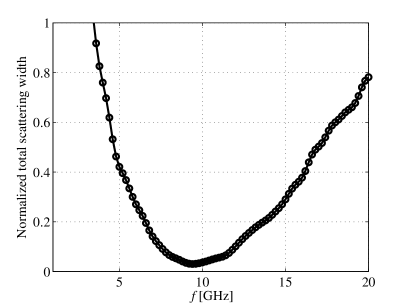
The numerical analysis of the studied structures is carried out with the commercial full-wave simulation software ANSYS HFSS [12]. The uncloaked and cloaked structures (see Figs. 1 and 2) are numerically modelled as being infinitely periodic in the -direction, by using symmetry boundaries. The uncloaked and cloaked objects are illuminated with a plane wave travelling in the -direction and having the electric field parallel to the -axis. From the simulated fields one can obtain the scattered fields (1) and the resulting normalized total scattering width (2) as a function of the frequency. The numerical result of (2) with integrating from to is presented in Fig. 4, showing that the cloak effectively reduces the total scattering width in a wide frequency band. In the band from 7.5 GHz to 11.9 GHz the total scattering width of the cloaked object is less than 10 % of the total scattering width of the uncloaked object.
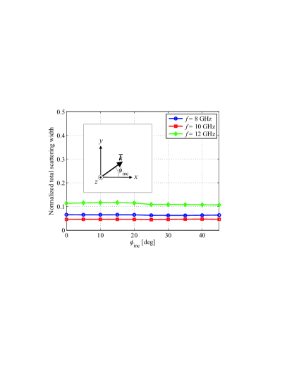
The isotropy of the cloaking effect can be studied by varying the incidence angle of the incoming plane wave. In this case we fix the frequency and study the normalized total scattering width as function of the incidence angle , see Fig. 5. Due to the symmetry of the structure, it is enough to study an angular range of , see Fig. 1a. Figure 5 demonstrates that the cloak behavior practically does not change with varying incidence angle. It should be noted that only TE incidence with the electric field parallel to the -axis is considered here. The cloaking effect can deteriorate for other polarizations.
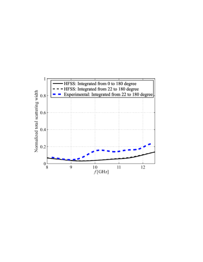
As explained in the previous section, the measurement setup is limited in the angular range. To take this limitation into account, in the following we compare the experimental results to two sets of numerical results: the one shown in Fig. 4 and one where the integration in (2) is done from to , as in the experiments. The two numerical results are shown together with the experimental result in Fig. 6. We can conclude that the two numerical results agree very well. This is explained by the fact that for both uncloaked and cloaked objects most of the scattering occurs in the forward direction (close to ) and scattering at low angles insignificantly contributes to the normalized total scattering width. Moreover, the scattered field amplitude for both the uncloaked and cloaked objects is almost constant with respect to for .
The experimental results shown in Fig. 6 demonstrate that the realized cloak works effectively in the whole X-band, but the cloaking effect is not quite as strong as in the numerical results. However, the broadband cloaking effect is clearly confirmed since the numerical results indicate that the cloak reduces the total scattering width by more than 90 % within the frequency band from 8.2 GHz to 11.9 GHz and the experimental results show reduction of more than 80 % in the same band.
Part of the disagreement between the numerical and experimental results can be due to measurement and fabrication inaccuracies and the non-ideal orientation of the cloak structure. Each of the transmission-line grids (each grid comprising one half of the parallel-strip transmission line) are manually inserted on top of each other and due to the insulation material between the adjacent grids, it is difficult to align the transmission-line strips exactly. We found that a positioning error of a few degrees can be easily introduced to the alignment and this was found by numerical simulations to result in deterioration of the cloaking effect in an amount comparable to the results shown in Fig. 6.
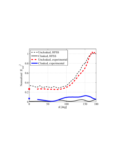
In addition to the normalized total scattering width it is interesting to take a look at the angular dependency of scattered fields in the cases of cloaked and uncloaked objects (Fig. 7). This analysis reveals the directions into which the objects scatter most. Here we fix the frequency to 10 GHz, i.e., close to the optimal cloaking frequency, and plot the scattered field intensities obtained from (1) as functions of the angle . To illustrate the cloaking effect, we normalize all the scattered field intensities to the intensity of the uncloaked object at . As explained in Section III, we can also use the monostatic measurement and (3) to confirm the levels of backscattering in uncloaked and cloaked cases. Figure 7 presents these results. Compared to the numerical results, the experimental curve in the cloaked case shows somewhat higher levels of scattering close to the forward direction, which evidently leads to higher level of the normalized total scattering width shown in Fig. 6. The monostatic measurements (marked with square and circle in Fig. 7) confirm that the scattering is quite stable with respect to the angle in the range from to .
V Conclusions
Bistatic measurements have been conducted in order to experimentally characterize the reduction of scattering from a metal object with a volumetric transmission-line structure used as an electromagnetic cloak at X-band. The characterization is done by comparing the measured total scattering widths of the object alone to the case when the same object is inserted inside the cloak. The results demonstrate a wide cloaking bandwidth. The total scattering width of the metal object is reduced by more than 80 % in a relative bandwidth of 40 % (8 GHz – 12 GHz). The measured results are compared to numerical results and these are in fairly good agreement with each other, although the numerical results indicate even slightly better cloaking performance.
References
- [1] P. Alitalo, O. Luukkonen, L. Jylhä, J. Venermo, and S. A. Tretyakov, “Transmission-line networks cloaking objects from electromagnetic fields,” IEEE Trans. Antennas Propag., vol. 56, no. 2, pp. 416–424, 2008.
- [2] P. Alitalo and S. A. Tretyakov, “Broadband electromagnetic cloaking realized with transmission-line and waveguiding structures,” Proceedings of the IEEE, vol. 99, no. 10, pp. 1646–1659, 2011.
- [3] J. B. Pendry, D. Schurig, and D. R. Smith, “Controlling electromagnetic fields”, Science, vol. 312, no. 5781, pp. 1780–1782, 2006.
- [4] H. Chen, C. T. Chan, and P. Sheng, “Transformation optics and metamaterials,” Nature Materials, vol. 9, pp. 387 396, 2010.
- [5] A. Alù and N. Engheta, “Achieving transparency with plasmonic and metamaterial coatings,” Phys. Rev. E, vol. 72, p. 016623, 2005.
- [6] A. Al and N. Engheta, “Plasmonic and metamaterial cloaking: physical mechanisms and potentials,” J. Opt. A, vol. 10, p. 093002, 2008.
- [7] J. Li and J. B. Pendry, “Hiding under the carpet: a new strategy for cloaking,” Phys. Rev. Lett., vol. 101, p. 203901, 2008.
- [8] R. Liu, C. Ji, J. J. Mock, J. Y. Chin, T. J. Cui, and D. R. Smith, “Broadband ground-plane cloak,” Science, vol. 323, no. 5912, pp. 366–369, 2009.
- [9] P. Alitalo, J. Vehmas, and S. A. Tretyakov, “Reduction of antenna blockage with a transmission-line cloak,” in Proc. 5th European Conference on Antennas and Propagation (EuCAP 2011), Rome, Italy, Apr. 11-15, 2011, pp. 2399-2402.
- [10] B. Edwards, A. Al, M. G. Silveirinha, and N. Engheta, “Experimental Verification of Plasmonic Cloaking at Microwave Frequencies with Metamaterials,” Phys. Rev. Lett., vol. 103, p. 153901, 2009.
- [11] N. Kundtz, D. Gaultney, and D. R. Smith, “Scattering cross-section of a transformation optics-based metamaterial cloak,” New J. Phys., vol. 12, p. 043039, 2010.
- [12] ANSYS homepage: http://www.ansys.com/
- [13] Homepage of Rohacell: http://www.rohacell.com