Status of the Super-B factory Design111Work supported by the Department of Energy under contract number DE-AC03-76SF00515.
Abstract
The SuperB international team continues to optimize the design of an electron-positron collider, which will allow the enhanced study of the origins of flavor physics. The project combines the best features of a linear collider (high single-collision luminosity) and a storage-ring collider (high repetition rate), bringing together all accelerator physics aspects to make a very high luminosity of 1036 cm-2 sec-1. This asymmetric-energy collider with a polarized electron beam will produce hundreds of millions of B-mesons at the (4S) resonance. The present design is based on extremely low emittance beams colliding at a large Piwinski angle to allow very low without the need for ultra short bunches. Use of crab-waist sextupoles will enhance the luminosity, suppressing dangerous resonances and allowing for a higher beam-beam parameter. The project has flexible beam parameters, improved dynamic aperture, and spin-rotators in the Low Energy Ring for longitudinal polarization of the electron beam at the Interaction Point. Optimized for best colliding-beam performance, the facility may also provide high-brightness photon beams for synchrotron radiation applications.
I Introduction
To achieve the design luminosity of in operation an ongoing effort of improvement is necessary. As part of this process new design options are explored and their effect on the design parameters studied. No individual option improves every single aspect of the machine and therefore all solutions have to be carefully compared and the solution with the overall best performance chosen. Part of this work is the study of unwanted effects, developing methods to compensate these and possibly test them in operating facilities. Based on these results design specifications and tolerances are developed. We report on the latest results of these efforts.
II Project Status
In December 2010 the Italian Ministry for Education, University and Research approved the SuperB project PressR . With this decision the project enters a new stage. The current conceptual design has been published in CDR2 . The Campus Tor Vergata near Rome, Italy was chosen as site for the facility. This was officially announced at the XVII SuperB Workshop and Kick Off Meeting in La Biodola (Isola d’Elba) Italy from 28 May 2011 to 02 June 2011. On October 7th the Laboratory Nicola Cabibbo was offically launched. The new international center for fundamental and applied physics is located on the campus of Rome Tor Vergate in Italy and will host the SuperB collider. The next goal is to deliver the engineering design report within the next year. Design construction has started.
III Latest Design Features
III.1 Design Parameters
All calculations discussed in this paper and CDR2 are based on the design parameters as summarized in table 1.
| Parameter | HER | LER |
|---|---|---|
| Luminosity [] | 1.00E36 | |
| Energy [GeV] | 6.7 | 4.18 |
| X-Angle (full) [mrad] | 66 | |
| [cm] | 2.6 | 3.2 |
| [cm] | 0.0253 | 0.0205 |
| (with IBS) [nm] | 2.07 | 2.37 |
| [pm] | 5.17 | 5.92 |
| Bunch length @ I=0 [mm] | 4.69 | 4.29 |
| Beam current [mA] | 1892 | 2447 |
| Tune shift x | 0.0021 | 0.0033 |
| Tune shift y | 0.0989 | 0.0955 |
| @ Imax [] | 6.43E-4 | 7.34E-4 |
| Lifetime [min] | 4.20 | 4.48 |
A complete list of parameters can be found at CDR2 .
III.2 IR Layout
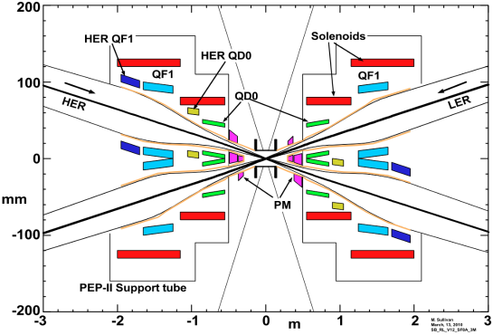
There are currently two designs under consideration for the interaction region layout. One bases its design on vanadium permendur Panofsky quadrupoles for QD0 and QF1 for both rings (”Russian” design) as shown in fig. 1.
The second utilizes superconducting air coils for QD0 and QF1 (”Italian” design). In addition a portion of the HER QD0 is laid out as vanadium permendur Panofsky quadrupole. Both solutions show good behavior for synchrotron radiation backgrounds and beam apertures. With respect to the detector solenoid compensation the latter option provides better compensation possibilities for both rings as different angles for QD0 and QF1 of HER and LER is the optimum solution.
III.3 QD0 prototype
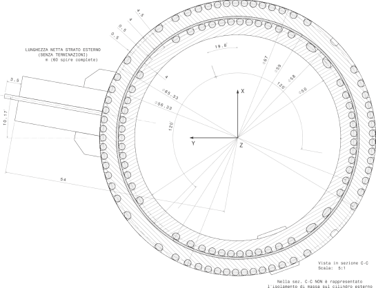
For the QD0 design a prototype of the superconducting ”Italian” design is being built. The quadrupole will have a magnetic length of 30 cm and a gradient of 96 T/m and an inner bore radius of 2 cm. Critical aspects are the small space available for the SC wire and the thermal stabilization material (Cu+Al), and the small margin to quench. The prototype will help in determining the maximum gradient achievable at 4.2K and the field quality at room temperature. See Fig. 2 for a sketch of the magnet.
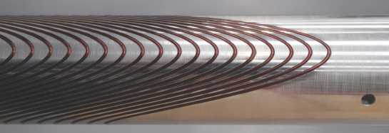
The aluminum structure supporting the superconducting wire has been constructed and a test winding installed in it as shown in Fig. 3.
III.4 Arc Cell Design
Over the past year two alternative arc cells have been developed. Three different versions for the HER arc cell were designed: V12 is the current version, V13 was modified to improve chromatic behavior and V14 to reduce the ring circumference. The major driver were the optimization of emittance, dynamic aperture, reduction of chromaticity for version 13 and reduction of ring circumference for version 14. The parameters for these new lattices are summarized in CalTechSum . A detailed description for both solutions is given in ArcCellR .
III.5 Compensation of Detector Solenoid
The detector solenoid has a strong 1.5 T field in the IR area, and its tails extend over the range of several meters. The coupling of the horizontal and vertical betatron motion needs to be corrected in order to preserve the small design beam size at the Interaction Point. Additional complications are: (1) The solenoid is not parallel to either of the two beams due to the crossing angle leading to orbit and dispersion perturbations. (2) The solenoid overlaps the innermost IR permanent quadrupoles causing additional coupling effects. The proposed correction system provides local compensation of the solenoid effects independently for each side of the IR. It includes bucking solenoids to remove the unwanted longitudinal solenoid field tails and a set of skew quadrupoles, dipole correctors and ante-solenoids to cancel all linear perturbations to the optics. The details of the correction system design are presented in Lattice .
III.6 Low Emittance Tuning
The ultra low vertical emittances in SuperB rings need a very careful procedure of emittance tuning, including the study of the maximum tolerable magnet errors (such as misalignments, tilts, BPM errors). To minimize the vertical emittance an orbit and dispersion as well as coupling and -beating free steering routine has been developed. The efficiency of this routine has been studied for the SuperB lattices with MADX. The results were presented in LETT . The SuperB final focus (FF) introduces stringent restrictions on alignment of both FF and arcs. To test the applicability of this method beam studies were conducted in late 2010 at the Diamond Light Source. In this test the vertical emittance correction was compared to the standard method using LOCO. These studies are still ongoing and preliminary results were presented in LETP .
III.7 Vibration Study
To establish a “vibration budget” an ongoing study investigates the effects of on beam sensitivity to dynamic misalignments. The major sources for these are expected to be the vibration of the IR cryostat. To confirm this the effects of ground motion as originally measured at LNF and later on the Tor Vergate site and the vibration of arc quadrupoles have been compared to the results for both sites. The results of the Tor Vergate site are favorable compared to the LNF site which contributed to the site choice. For this investigation ground motion measurements at LNF site at Frascati and Tor Vergata, vibration measurement at the SLD detector at SLAC are combined with theoretical modeling. To establish the budget a maximum allowed orbit displacement at the interaction point reducing the luminosity is defined. The preliminary results are summarized in table 2.
| Element | RMS | Transfer | RMS differiential | |
|---|---|---|---|---|
| motion per | Function | displacement at IP | ||
| element | (RMS sum, | no | with | |
| both rings) | feedback | feedback | ||
| Cryostat linear | ||||
| Cryostat rotation | ||||
| Final focus quads, excluding IR | ||||
| Arc | ||||
| Total (two rings) | ||||
These results are based on the assumption that the beam feedback achieves a 10 times reduction of motion at IP. Also the integrated RMS motion is larger than 1 Hertz. By achieving these values the relative beam motion at the IP will be within 8 nm and the luminosity loss below one percent. This work has been presented in vibration .
III.8 Effect of Second Order Momentum Compaction
A longitudinal head-tail instability can appear when the momentum compaction shows a strong nonlinear energy dependency chao . The momentum compaction can be developed as a function of energy spread as follows: . This particular instability is affected by the combination of nonlinear momentum compaction and beam impedance. To better understand its effect it was studied using the code described in SashaCode . It showed the behavior of an saw tooth instability as depicted in fig. 4.
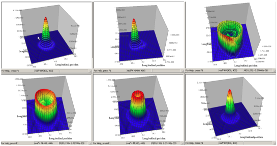
The following preliminary results were obtained: (1) Second order term of momentum compaction may play important role in the longitudinal beam dynamics for low compaction machines. (2) There is no instability threshold for a positive value of . (3) It is necessary to check that the second part of the momentum compaction of the Super-B lattice has the right sign, or at least is less than 0.05, if it is positive. During operation of the DANE collider this behavior has been observed in the past. With this study the effects could be understood and, more important, provide the knowledge on how to avoid it.
IV Synchrotron Light Option
The possibility of using the HER and LER storage rings as third generation light source have been investigated. As an initial step the performance of both rings were compared to state of the art facilities in operation, construction and design LightSource . Both HER and LER compare favorable in this study. As a result the synchrotron light option has been made integral part of the Super-B project. A preliminary analysis was performed of the ring geometry locating synchrotron light beam lines on the LNF site at Frascati. This work is applicable to the Tor Vergata campus. The This is work in progress. Adding the functionality of a light source to the project will impact other decissions.
The design parameters relevant to this study, are shown in Table 3. As comparison the design parameters from NSLS II NSLSII and other state of the art synchrotron light sources have been added to this table. From these parameters it is obvious that synchrotron radiation generated from both HER and LER is comparable to this last generation sources.
IV.1 Benchmark Results
To quantify the statement above the synchrotron radiation generated from both rings using bend magnets and standard undulators have been analytically calculated using the formalism described in XRB . A MATLAB script was used to calculate the bessel functions and calculate flux, and brightness. To verify this setup a benchmark test was performed with a set of parameters and results calculated with an alternative code. As comparison the same calculations have been performed for other light sources to benchmark both HER and LER. For the comparison state of the art facilities in operation, construction and design are used.
IV.1.1 Bend Magnet
Bend magnet radiation is parasitically generated in any collider and no change to the optics needs to be implemented. Although most third generation light sources are optimized for undulator and wiggler beam lines bend magnet sources are part of future designs and their performance optimized. The brightness for the different facilities is shown in Figure 5.
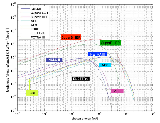
The parameters used for the calculations are those in Table 3. The data were extracted from the facilities web pages, CDR’s and presentations. Future facilities like PEPX are not included here as no data was available for it.
| Param. | HER | LER | NSLS II | APS | ESRF | ELETTRA | ALS |
|---|---|---|---|---|---|---|---|
| E[GeV] | 6.7 | 4.18 | 3.0 | 7.0 | 6.03 | 2.0 | 1.9 |
| I[mA] | 1892 | 2447 | 500 | 100 | 200 | 320 | 500 |
| [m] | 69.6 | 26.8 | 24.98 | 38.96 | 23.62 | 5.55 | 4.81 |
| [nm] | 2.0 | 2.46 | 0.55 | 2.51 | 4.0 | 7.0 | 6.3 |
| [pm] | 5.0 | 6.15 | 8.0 | 22.6 | 25.0 | 70.0 | 50.0 |
| [m-1] | 0.33 | 0.54 | 0.05 | 0.101 | 0.10 | 0.50 | 0.74 |
| [mm] | 82.1 | 92.1 | 125 | 81.7 | 77.0 | 139 | 102 |
| [mm] | 8.66 | 9.11 | 13.4 | 27.0 | 29.5 | 28.0 | 8.20 |
For bend magnets the HER and LER have the brightest photon beam. However the offset to the other sources is smaller as the source parameters (beam emittance and divergence) are less optimized. The results for photon flux is not shown here, since it is dominated by beam current and the HER and LER will have the highest.
IV.1.2 Undulators
The figure of merit for third generation light sources is the radiation generated from insertion devices. For this purpose the undulator radiation as documented on the same sources quoted above have been used for facilities in operation and construction. For better comparison the same device type as at NSLS II was chosen for the Super-B HER and LER. Source point and device parameters are summarized in Table 4.
| Param. | HER | LER | NSLS II | APS | PEPX | Soleil | Spring8 | Petra III |
|---|---|---|---|---|---|---|---|---|
| Undulator | IVU20 | IVU20 | IVU20 | U33 | IVU23 | U20 | U24 | U29 |
| E[GeV] | 6.7 | 4.18 | 3.0 | 7.0 | 4.5 | 2.75 | 8.0 | 6.0 |
| I[mA] | 1892 | 2447 | 500 | 100 | 1500 | 500 | 100 | 100 |
| [m] | 82.1 | 92.1 | 125 | 81.7 | 22.2 | 3880 | 286 | 140 |
| [m] | 8.66 | 9.11 | 13.4 | 27.0 | 7.00 | 8.08 | 6.00 | 5.60 |
| [mrad] | 33.3 | 37.0 | 16.5 | 11.8 | 7.40 | 14.5 | 11.0 | 7.9 |
| [mrad] | 2.1 | 2.7 | 2.7 | 3.3 | 1.2 | 4.6 | 1.0 | 4.1 |
| N[1] | 148 | 148 | 148 | 72 | 150 | 90 | 186 | 172 |
| [mm] | 20 | 20 | 20 | 33 | 23 | 20 | 24 | 29 |
| Kmax[1] | 1.83 | 1.83 | 1.83 | 2.75 | 2.26 | 1.0 | 2.21 | 2.2 |
| Kmin[1] | 0.1 | 0.1 | 0.1 | 0.1 | 0.1 | 0.1 | 0.1 | 0.1 |
The brightness for the undulator radiation is depicted in Figure 6.
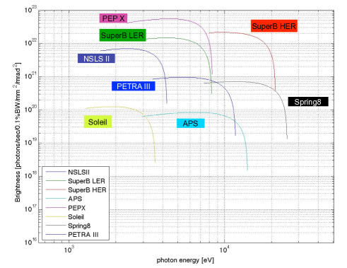
PEPX generates the highest brightness followed by HER and LER. This is a result of the high beam currents in these rings. A detailed study of the difference of source point parameter and its effect on the brightness between PEPX and the Super-B rings by considering the photon beam diffraction limit showed that the higher brightness in PEPX is generated by its lower horizontal emittance.
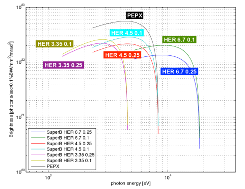
IV.1.3 Source Parameter Optimization
A brief study to optimize the brightness in the HER was conducted, the result is plotted in Figure 7. By reducing the HER energy and beam coupling (from design 0.25% to 0.1%) the beam emittance is reduced. This gain is unfortunately mostly canceled by the change of the diffraction limit as the calculation show, since to achieve the same level of brightness as in PEPX the horizontal emittance would have to be significantly reduced.
IV.2 Beam Line Layout
When using the Super-B rings as a synchrotron light source one has to plan for additional space for the photon beam lines and user space. This is significant as collider facilities are usually located underground for radiation protection purposes whereas third generation light sources are surface installations.
IV.2.1 LNF Site at Frascati Rome
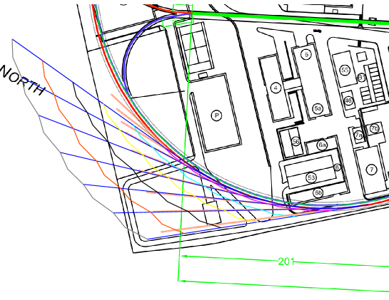
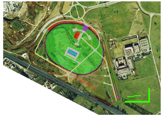
During the study the LNF site near Rome was the primary choice. This site demands an underground installation as the surface area is already mostly occupied. In addition the ring dimensions partially exceed the LNF boundaries. This investigation was aimed to understand where and with what length photon beam lines could be placed within the LNF boundary. An overview is shown in Figure 8. It shows the planned Super-B tunnels with injector. Added to these are the contour lines with distances from the source point in 25 meter steps to a maximum of 150 meters. Only bend magnet source points from the outer ring were used. the upper portion of beam lines originate from the LER the lower from the HER.
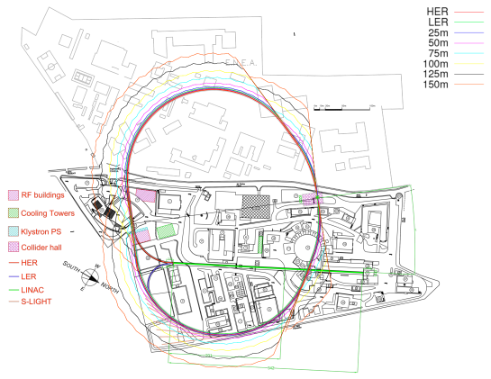
Figure 9 is a magnification of the lower left area. As the picture indicates a set of HER beam lines with different length could be located there completely within LNF boundaries. The same contour line legend of Fig.8 applies.
IV.2.2 Campus Tor Vergata Rome
With the decission in favour for the Tor Vergate site the space constraints discussed in the previous section are relaxed. This site is located about 4 kilometers from the original area of LNF. The preliminary results of the ground motion measurements show less activity at this site. A first scetch of the accelerator design at Tor Vergata as originaly planned for the LNF site is shown in Fig. 10.
V CONCLUSIONS
With the approval by the Italian government the project is moving from the conceptual to the technical design phase. With the establishing of the Laboratory Nicola Cabibbo at the Campus Tor Vergata as the future site of the SuperB facility a large step has been taken towards the realization. The collaboration with other funding agencies, through MOU, is in its final phase. Construction plans will follow soon.
References
- (1) INFN media and press release, “The Italian Government Funds the Super-B Accelerator ”, Friday, 24 December 2010, http://web.infn.it/superb/en/media-and-press- release
- (2) SuperB Collaboration: M. Biagini, P. Raimondi, J. Seeman, “SuperB Progress Reports – Accelerator”, http://arxiv.org/abs/1009.6178v2
- (3) M. Biagini, “SuperB Accelerator Status”, XV SuperB Workshop Caltech, CA, Dec. 14-17, 2010
- (4) S. Sinyatkin, “Review of new High Energy Rings”, XIV SuperB General Meeting Frascati September 28, 2010
- (5) W. Wittmer et. al., “Synchrotron Light Options at Super-B”, Particle Accelerator Conference (PAC’11), March 28 to April 1, 2011.
- (6) Y. Nosochkov et. al.,“Compensation of Detector Solenoid in SUPER-B”, Particle Accelerator Conference (PAC’11), March 28 to April 1, 2011.
- (7) S. Liuzzo, “Latest on Low Emittance Tuning LER. Without Final Focus & With Final Focus”, XIV SuperB General Meeting Frascati September 28, 2010
- (8) S. Liuzzo et. al., “Low Emittance Tuning Tests at the Diamond Light Source (Rutherford Labs) Dec. 2010”, XV SuperB Workshop Caltech, CA, Dec. 14-17, 2010
- (9) K. Bertsche, “Vibration Requirements and Vibration Requirements and Expectations For SuperB”, XV SuperB Workshop Caltech, CA, Dec. 14-17, 2010
- (10) A. Chao, M. Tigner, “Handbook of Accelerator. Physics and Engineering”, p119, 1999 by World Scientific Publishing Co. Pte. Ltd.
- (11) A. Novokhatski, “Computer Algorithm for Longitudinal Single Bunch Stability Study in a Storage Ring”, SLAC-PUB-11251, May 2005.
- (12) “NSLS-II Proposal for Approval of Conceptual Design (CD-0)”, http://www.bnl.gov/nsls2/.
- (13) Center for X-ray Optics and Advanced Light Source, “X-RAY DATA BOOKLET”, http://xdb.lbl.gov/.