Optimisation of hybrid high-modulus/high-strength carbon fiber reinforced
plastic composite drive
Abstract
This study deals with the optimisation of hybrid composite drive shafts operating at subcritical or supercritical speeds, using a genetic algorithm. A formulation for the flexural vibrations of a composite drive shaft mounted on viscoelastic supports including shear effects is developed. In particular, an analytic stability criterion is developed to ensure the integrity of the system in the supercritical regime. Then it is shown that the torsional strength can be computed with the maximum stress criterion. A shell method is developed for computing drive shaft torsional buckling. The optimisation of a helicopter tail rotor driveline is then performed. In particular, original hybrid shafts consisting of high-modulus and high-strength carbon fibre reinforced epoxy plies were studied. The solutions obtained using the method presented here made it possible to greatly decrease the number of shafts and the weight of the driveline under subcritical conditions, and even more under supercritical conditions. This study yielded some general rules for designing an optimum composite shaft without any need for optimisation algorithms.
keywords:
Drive shaft, Optimisation, Hybrid carbon fibre reinforced plastic| Nomenclature | |
| , | in-plane stiffness matrix of the laminate and elements of the matrix () |
| , | in-plane compliance matrix of the laminate and elements of the matrix |
| , | coupling stiffness matrix of the laminate and elements of the matrix |
| viscous damping | |
| , | flexural stiffness matrix of the laminate and elements of the matrix |
| longitudinal Young’s modulus of the shaft | |
| , , , , , | longitudinal and transverse Young’s modulus, Poisson’s ratio, out-of-plane (transverse / normal, longitudinal / normal) and in-plane shear modulus of the ply |
| fitness function | |
| transverse shear modulus of the shaft | |
| constraint function | |
| number of half-wave along the circumference | |
| , | transverse area moments of inertia of the shaft |
| polar mass moment of inertia | |
| buckling stiffness matrix | |
| reserve factors | |
| stiffness | |
| unsupported shaft section length | |
| mass | |
| number of plies | |
| power | |
| number of half-wave along the axis | |
| number of possible orientations in the staking sequence | |
| shaft radius | |
| cross-section area of the shaft | |
| thickness or time | |
| axial torque | |
| , , | displacements (complex or real) |
| , , , , | tensile and compressive longitudinal strength, tensile and compressive transverse strength, in-plane shear strength |
| , , | coordinates |
| orientation of the ply | |
| loss factor | |
| shear coefficient | |
| Poisson’s ratio of the shaft | |
| distribution of the torsional modes | |
| mass density of the shaft | |
| angular position | |
| out-of plane cross-section rotation (complex or real) | |
| , , | in-plane stress of the ply (longitudinal, transverse and shear) |
| natural frequency of the torsional modes | |
| natural frequency of the flexural modes | |
| spin speed | |
| Subscript | |
| , , | lower and higher backward whirl speeds |
| bearing | |
| buckling | |
| critical | |
| driveline | |
| external | |
| equivalent | |
| , | lower and higher forward whirl speeds |
| flexural modes | |
| gear | |
| internal | |
| inferior | |
| medium | |
| minimum | |
| material of a ply | |
| nominal | |
| number of sine modes | |
| laminate ply | |
| shaft | |
| superior | |
| tail rotor | |
| torsional modes | |
| threshold speed | |
| strength |
1 Introduction
Since the 1970s, composite materials have been regarded as potential candidates for manufacturing drive shafts because of their high specific stiffness and strength [1]. Previous studies on this topic have dealt mainly with composite shaft design in the subcritical case, that is when the first critical speed is never exceeded. However, when a long driveline is required (in the case of helicopters, tilt-rotors, tailless aircraft with twin turboprops, etc.), an additional means of increasing the drive shaft length consists in operating above the first critical speed, in the so-called supercritical regime. The main advantage of long shafts is that they reduce the number of bearing supports required, and thus greatly decrease the maintenance costs and the weight of the driveline. The design process is more complex, however, because the shaft has to cross a critical speed, and dynamic instabilities due to rotating damping can occur in this regime. Aeronautic applications lend themselves well to operating in the supercritical regime because the driveline always rotates at the nominal speed during flight, since they undergo acceleration and deceleration processes on the ground. The aim of this paper is to optimise a supercritical drive shaft in this practical case.
Many different numerical methods have been used to design optimised composite drive shafts in order to reduce their weight, for example. Traditional methods based on the gradients of continuous functions have been used for this purpose by several authors [2, 3, 4]. These methods are unsuitable in the case of composite laminates, however, because many of the variables which have to be optimised are discrete variables (such as the number of plies and the ply angle in prepreg lay-up processes). It is therefore necessary to assume these variables to be continuous to be able to compute the gradients required. The optimisation techniques available for solving problems involving discrete variables are known as metaheuristic methods. For example, Gubran and Gupta [5] have used simulated annealing techniques based on a neighbourhood approach. A review of the literature shows that genetic algorithms (GA) [6, 7] are well adapted to designing laminate structures. GA were recently used to optimise a flexible matrix composite drive shaft in [8]. Here it is proposed to use a GA with penalisation methods to account for the constraint functions. In addition, in order to reduce the CPU time, all the design aspects are handled without requiring the use of finite element methods.
In drive shaft applications, the choice of composite material is of great importance. Several authors have recommended the use of hybrid composites in the production of drive shafts. Xu et al. [9], Gubran [10], and Badie et al. [11] recently studied the advantages of a mixture of glass and carbon fibres in a modified epoxy matrix. Lee et al. [12], Gubran [10], Mutasher [13] and Abu Talib et al. [14] recently have studied the design and manufacture of hybrid metallic/composite drive shafts. Here it is proposed to study the use of a combination of high-modulus (HM) and high-strength (HS) carbon fibre reinforced epoxy plies, in order to benefit from the main advantages of each type of fibre. The main design considerations in the case of composite laminate tubes are the axial stiffness and the torsional resistance. In this particular case, the plies providing stiffness and strength can be considered practically separately [15]. HM carbon/epoxy, which have poor strength properties, especially when exposed to compression loads [16], can serve to maximise the axial stiffness. HS carbon/epoxy can be used to maximise the resistance to torsion loads. Note that the hybridization can be simply obtained by using the same resin with both fibres. Otherwise, it would be necessary to verify the compatibility of the two resins (in terms of their curing cycle behaviour, adhesiveness, etc.). For the sake of convenience, this point is not taken into account here.
The first part of this paper presents various design aspects. In particular, the dynamic of a drive shaft is studied at supercritical speeds. The failure strength analysis focuses on the choice of the stress criterion. A composite shell model is then developed for the torsional buckling. In the second part, the GA is presented. The last part presents a comparative study between HM and hybrid solutions on a helicopter tail rotor driveline previously presented in the literature.
2 Design aspects
2.1 Flexural vibration analysis
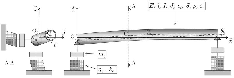
When designing supercritical shafts, the external damping has to be maximised in order to reduce the flexural imbalance responses and increase the stability in the supercritical regime. Rolling-element bearings provide insufficient damping. Dissipative materials such as elastomers have recently been used as bearing supports as a passive means of enhancing the non-rotating damping [17, 18]. A low cost configuration consisting of an axisymmetric composite shaft simply supported on classical rolling-element bearings mounted on viscoelastic supports was studied here (Fig. 1).
| Material | Abbr. | |||||||||||
|---|---|---|---|---|---|---|---|---|---|---|---|---|
| kg m-3 | GPa | GPa | GPa | - | MPa | MPa | MPa | MPa | MPa | mm | ||
| Narmco 5505 [1] | BEa | 1 965 | 211 | 24.1 | 6.89 | 0.36 | 1 365 | 1 586 | 45 | 213 | 62 | 0.1321 |
| T300/5208 [3, 4] | CEL. | 1 680 | 181 | 10.3 | 7.17 | 0.28 | 1 500 | 1 500 | 40 | 246 | 68 | |
| K63712/M10 [16] | HM | 1 700 | 370 | 5.4 | 4.0 | 0.3 | 1 500 | 470 | 35 | 200 | 75 | 0.125 |
| T800/G947 | HS | 1 530 | 162 | 10 | 5.0 | 0.3 | 2 940 | 1 570 | 60 | 290 | 100 | 0.125 |
a BE : boron/epoxy ; CE : carbon/epoxy
Various approaches based on beam and shell theories have been used to compute the critical speeds of composite shafts [19, 20, 21], most of which were placed on infinitely rigid supports. The simplest of these theories is called the Equivalent Modulus Beam Theory (EMBT) [1]. Based on this approach, it is proposed to investigate a rotating beam with Timoshenko’s assumptions [22], replacing the isotropic properties of the material by the homogenised properties of the composite. These equations are also adapted to account for the motion of the supports and the internal damping terms. Lastly, the three complex governing equations and boundary conditions used can be written in the following form:
| (1) | |||
| (2) | |||
| (3) | |||
| (4) |
where , , , is the cross-sectional displacement and is the deflection of the shaft (see the list of nomenclature for the other parameters). Using the method presented in [18], the above equations yield the four critical speeds for the harmonic:
| (5) |
| (6) |
where
| (7) |
In addition, in the case of a composite shaft consisting of a symmetric laminate, the homogenised properties can be computed with the following equations: , and where [23]. It is also assumed that .
In the field of rotordynamics, internal damping, which is also referred to as rotating damping, is known to cause whirl instability in the supercritical regime. In the literature, the internal damping resulting from dissipation in the shaft material and dry friction between the assembled components has been usually approached using the viscous damping model. However, most materials, such as carbon/epoxy materials in particular, show vibratory damping, which resembles hysteretic damping much more than viscous damping [24, 25]. Using the classical equivalence between viscous and hysteretic damping [18], the analytical instability criterion suitable for shaft optimisation purposes, can be written in the following form:
| (8) |
where
| (9) |
and where the equivalent longitudinal loss factor denoted is computed with Adams, Bacon and Ni’s theory [26, 27] using complex properties of the ply (0.11 %, 0.70 % and 1.10 %). It then suffices to compute the lowest threshold speed in order to determine the spin speed limit of the shaft.
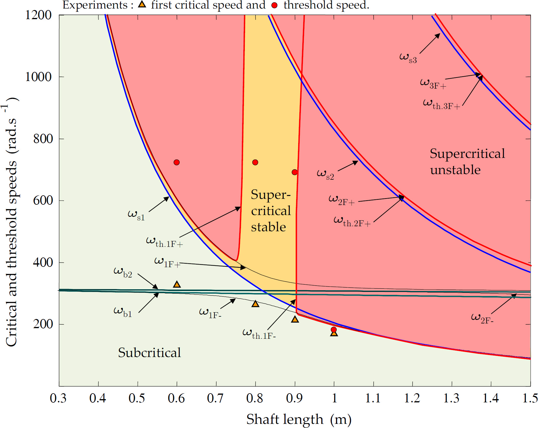
A dynamic shaft test rig corresponding to the case of Fig. 1 has been developed to validate the theoretical results (Fig. 2). Basically, the test rig consists in a shaft that is powered by an electric motor via a belt and pulley system and is capable of a maximum test velocity of 12 000 rpm. Two non-contact laser-optical displacement sensors are able to measure the cross-section displacement in real-time. The detailed characteristics of the test rig are given in [25, 28]. In the case of a long aluminium shaft ( GPa, kg.m-1, m, mm, mm) supported on viscoelastic supports ( kg, N.m-1), the critical speeds and were measured to be rad.s-1 and rad.s-1, respectively. The results obtained with the above model are rad.s-1 and rad.s-1 which is very close to the experiment.
The experimental investigation of the instabilities can initiate catastrophic risks for the dynamic test rig. For this reason, it was proposed to study the instabilities using PVC material. Another advantage of the PVC material is its low stiffness and high damping ( GPa, kg.m-1 and %) which decrease the critical and threshold speeds. Several shafts with four different lengths were tested in the supercritical domain ( mm, mm with kg, N.m-1 and %). A high level of acceleration was required in order to run over the first critical speed. Only the shafts of length 0.8 m and 0.9 m were found to be stable in the supercritical regime. The theoretical model is compared to experimental results in the Fig. 3. A relatively good correlation is obtained considering these experiments are difficult to achieve. Note that the stability area is obtained at the intersection of the rigid body mode and the first flexural mode ( m).

2.2 Torsional vibration analysis
Torsional vibrations are computed using classical methods with the relations presented by Lim and Darlow [3]:
| (10) |
with
where , and are the mass moment of inertia of the main gearing, the tail rotor and the shaft, respectively.
2.3 Failure strength analysis
Only the torsional resistance of the shaft is taken into account here. The transmitted torque causes only in-plane shear, which can be computed with classical laminate theory [23]. Contrary to what occurs with an unsymmetrical free-edge laminate plate, the tubular structure blocks the coupling effects in the case of small displacements. This can be modelled simply by assuming the classical coupling matrix to be null before performing the inversion procedure required to compute the strain state.
A conservative approach often used in the case of helicopter drive shafts consists in computing only the fracture of the first ply. The Tsai-Wu criterion [29] can be used in this case to account for the differences between the tensile and compressive strengths, which can be of great importance in the case of HM carbon/epoxy (see Table 1):
| (11) |
where is an interaction parameter which is taken to be equal to 0.5. It should be noted that the Tsai-Wu criterion includes the transverse fracture mechanism. In the HS carbon/epoxy material, the transverse failure strain is approximately equal to 0.6 %, while the longitudinal one is equal to 1.8 %. This type of fracture generally has no direct effects on the fracture of the laminate, and this approach therefore seems to be too conservative. Assuming that the structure will be safe up to the occurrence of the first longitudinal or shear failure, a more realistic torque resistance limit can be obtained [15, 30]. This limit can be computed quite simply with a maximum stress criterion:
| (12) |
The comparisons made in Table 2 between the results obtained with these criteria and the experimental data confirm the validity of this approach. In the case of tubes Nos. 1 and 2, the values obtained with the maximum stress criterion showed better agreement with the experimental data than those obtained using the Tsai-Wu criterion. The assumption involving the presence of a null coupling mechanism in the case of unsymmetrical laminates was also found to be true. The Tsai-Wu values could be improved by taking a greater transverse tensile strength .
| Nos. | 1 | 2 | 3 | |
|---|---|---|---|---|
| Stacking sequence (from inner to outer radius) | ° | [90,45,-45,90] | [90,45,-45,06,90] | [90,02,90] |
| Outer radius length | mm | 25.4 50.8 | 63.5305 | 25.450.8 |
| Experimental [1] | N.m | 581 | 4689a | 132 |
| Tsai-Wu criterion | N.m | 167 (-71%) | 1605 (-66%) | 130 (3%) |
| Tsai-Wu criterion with | N.m | 313 (-46%) | 2613 (-44%) | 130 (3%) |
| Maximum stress in fibre and shear directions | N.m | 517 (-10%) | 1610 (-66%) | 130 (3%) |
| Maximum stress in fibre and shear directions with | N.m | 585 (2%) | 4880 (4%) | 130 (3%) |
| Buckling torque computed with Hayashi [31] criterion | N.m | 1049 | 13 016 | 1547 |
a Mean value of two specimen tests.
2.4 Torsional buckling analysis
Finite element methods are those most frequently employed to predict torsional buckling. However, an alternative method is presented here, which requires less computing time, and consists in solving the buckling shell problem in the case of orthotropic circular cylinders, using Fl gge’s buckling shell theory [32]. The laminate theory is included in the shell equations, as established in [33]. This gives the Eqs. (28-30) (see A). Since we are dealing here with very long shafts, it is possible to neglect the boundary condition effects. In this case, a simplified displacement field presented by Fl gge can be used:
| (13) |
where is the displacement field of the middle-surface of the cylinder, is the number of half-waves along the cylinder’s circumference and is the number of half-waves along the axis of the cylinder with a fictive length . When this displacement field is applied to the shell equations, a classical eigenvalue problem is obtained:
| (14) |
where is the stiffness matrix (the elements of are given in A). A non-trivial solution exists when the determinant of is null.
The numerical method used here consists in finding the minimum value of the buckling torque which cancels the determinant among all the values of and . The computing time was reduced as follows. First, we have observed that the minimum value of the buckling torque is always obtained at . Secondly, instead of searching for the value of between and , this unknown can be found by searching around the value of obtained by Flügge [32] in the case of isotropic material. Thirdly, the search for the buckling torque is conducted around the value of , which can be obtained with an analytic criterion such as Hayashi’s criterion [31]:
| (15) |
It is worth noting that this criterion, like other classical criteria, does not account for the coupling mechanism involved in unsymmetrical laminates.
The shell method was first tested on off-axis stacking sequences. The buckling torque obtained are presented in Table 3 and compared with those obtained with the finite element method, the above criterion and by Bert and Kim [33]. The results obtained with the finite element method using ABAQUS (s4 elements) [34], which were previously validated in [25] based on experimental results obtained by Bauchau et al. [35] in the case of short tube, are taken as reference values. Bert and Kim buckling theory is based on the Sanders shell theory and take the boundary conditions into account. In the table, the results obtained by Bert and Kim correlate perfectly well with the finite element computations. Those obtained with the method presented here show higher differences which is explain by the too low length-to-diameter ratio (). The results show the highest differences at the extremum cases (0° and 90°) which yet are symmetric, hovewer, the method is conservative. The error obtained with the Hayashi criterion can reach 82%.
The shell method was then tested on unsymmetrical stacking sequences for higher length-to-diameter ratio () in Table 4. All the tubes presented in the table are of the same size and the laminates all have the same thickness. Buckling torque was computed in the positive and then in the negative direction. The table shows that the Hayashi criterion overestimates the buckling torque, especially in the largest unsymmetrical laminates (Nos. 9-12) by up to 40%. The results obtained with shell theory show good agreement with the finite element calculations, giving a conservative estimate on the whole. The largest errors amounted to only 8% and the mean error was 4%.
| Ply orientation angle | ° | 0 | 15 | 30 | 45 | 60 | 75 | 90 |
|---|---|---|---|---|---|---|---|---|
| Abaqus | N.m | 1 489 | 974 | 1 121 | 1 769 | 2 587 | 3 131 | 3 278 |
| Present work | N.m (%) | 966 (-35) | 755 (-22) | 979 (-13) | 1 647 (-7) | 2 445 (-5) | 2 957 (-6) | 2 835 (-14) |
| Bert & Kim | N.m (%) | 1 587 (7) | 974 (0) | 1 126 (0) | 1 790 (1) | 2 617 (1) | 3 156 (1) | 3 016 (-8) |
| Hayashi criterion | N.m (%) | 1 887 (27) | 1 776 (82) | 1 607 (43) | 1 648 (-7) | 2 216 (-14) | 3 925 (-25) | 3 365 (3) |
| Laminate | ABAQUS | Present | Hayashi | |||||||
|---|---|---|---|---|---|---|---|---|---|---|
| work | criterion | |||||||||
| Nos. | Mesha | Nm | Nm | % | Nm | % | ||||
| 1 | [15,-15]4 | 60-150 | 210 | 193 | -8 | 222 | 6 | |||
| 2 | [-15,15]4 | 60-150 | 214 | 197 | -8 | 222 | 4 | |||
| 3 | [30,-30]4 | 60-150 | 263 | 254 | -4 | 283 | 8 | |||
| 4 | [-30,30]4 | 60-150 | 268 | 259 | -3 | 283 | 6 | |||
| 5 | [45,-45]4 | 60-150 | 385 | 383 | -1 | 419 | 9 | |||
| 6 | [-45,45]4 | 60-150 | 385 | 382 | -1 | 419 | 9 | |||
| 7 | [02,45,-45,45,-45,02] | 60-150 | 230 | 218 | -5 | 252 | 10 | |||
| 8 | [02,-45,45,-45,45,02] | 60-150 | 219 | 208 | -5 | 252 | 15 | |||
| 9 | [02,45,0,-45,0,45,-45] | 30-100 | 358 | 342 | -4 | 420 | 17 | |||
| 10 | [02,-45,0,45,0,-45,45] | 30-100 | 329 | 315 | -4 | 420 | 28 | |||
| 11 | [02,45,02,-45,45,-45] | 30-100 | 355 | 340 | -4 | 440 | 24 | |||
| 12 | [02,-45,02,45,-45,45] | 30-100 | 313 | 300 | -4 | 440 | 41 | |||
| 13 | [-45,-15,15,45,15,-15,-45,45] | 60-150 | 389 | 375 | -4 | 493 | 27 | |||
| 14 | [45,15,-15,-45,-15,15,45,-45] | 60-150 | 439 | 449 | 2 | 493 | 12 | |||
| 15 | [15,-15,-45,-15,15,45,15,-15] | 60-150 | 219 | 206 | -6 | 265 | 21 | |||
| 16 | [-15,15,45,15,-15,-45,-15,15] | 60-150 | 241 | 226 | -6 | 265 | 10 | |||
a Number of circumferential elements - number of lengthwise elements.
2.5 Driveline mass
The driveline is composed of shafts and intermediate supports, which include bearings, fittings, and supports. The intermediate support mass can be computed with an empirical equation from Lim and Darlow [3]:
| (16) |
where is the power transmitted with the driveline (in W) and is the nominal spin speed (in rev / min). The driveline’s mass can then be computed using the following expression:
| (17) |
where is the number of shafts and is the number of intermediate supports.
3 Shaft optimisation using a genetic algorithm
The principles underlying the GA algorithm are the same as those on which Darwin’s theory of evolution was based. At the beginning, a randomly created population is evaluated with a fitness function. The result gives the fitness of each individual. Starting with this information, the new generation of the population can be deduced using selection, crossover and mutation operators. This process is iterated up to convergence.
The main risk with this stochastic method is that of not obtaining the optimum solution. In particular, GA may tend to converge on local optima and may not be able to cross these attracting points. Another weakness of the method is the large amount of fitness function calculations required. This means that the evaluation procedure must not be too time-consuming.
3.1 Individual
An individual in this driveline optimisation procedure consists of the medium diameter (which can be fixed or otherwise), the bearing stiffness (fixed or not), the nominal spin speed and the stacking sequence with various materials, symmetric or otherwise, as in the following example: where , and are the orientation, the number of plies and the material of which the ply is made, respectively. Under supercritical conditions, the stiffness of the bearings is a necessary optimisation variable because it appears in both the rigid mode frequencies Eq. (7) and the stability criterion Eq. (8). The shaft length corresponds to the driveline length divided by the number of shafts.
There are several possible ways of modelling the chromosomes of individuals. It is proposed here to fix the number of possible orientations in the stacking sequence, denoted . This sets the size of the chromosome in the case of a particular optimisation process, which simplifies the crossover operations. Individuals are classically represented by an array of binary numbers. The orientation can be written with 2 or 3 bits, standing for the sets {-45, 0, 45, 90} or {-67.5, -45, -22.5, 0, 22.5, 45, 67.5, 90} (in degree units), respectively, which correspond to realistic prepreg hand lay-up orientations. The quantity is written with 2 or 3 bits corresponding to the sets {1,2,3,4} and {1,2,3,4,5,6,7,8}, respectively. The material is written with one bit to take advantage of both HM and HS carbon/epoxy, or metal and HM carbon/epoxy, for example. Lastly, and are bounded and generally encoded with 3 bits. For example, a shaft with the following stacking sequence (i.e. ), with 52 mm and 4000 rev / min, with the bearing stiffness fixed and where and are encoded with 2 bits, with 4 bits, with 3 bits and with 1 bit, is defined by the following chromosome:
The string length is therefore simply .
3.2 Constraints and fitness
The mass is the optimised value generally used in driveline problems [3, 5]. In this paper, part of the fitness function is equal to the inverse of the mass of one shaft. The other part depends on the strength, buckling and dynamic constraints previously investigated ():
| (18) | |||
| (19) | |||
| (20) | |||
| (21) | |||
| (22) |
and in the subcritical case
| (23) |
or in the supercritical case
| (24) | |||
| (25) | |||
| (26) |
where and are constraint functions and reserve factors, respectively. Eq. (18) corresponds to the torsional strength constraint, which requires that the torque computed with the strength criterion multiplied by the reserve factor is smaller than the torque required. Eq. (19) is the same equation but for the torsional buckling. The other equations are those giving the dynamic constraints. Eqs. (21-22) correspond to the positioning of the nominal spin speed between torsional modal frequencies. As regards the bending modes, the constraints depend on whether the subcritical or supercritical case applies. In the first case, Eq. (23) corresponds to the subcritical assumption, i.e. the nominal spin speed multiplied by the reserve factor must be smaller than the first critical speed. In the supercritical case, Eqs. (24-25) correspond to the positioning of the nominal spin speed between the flexural critical speeds, and Eq. (26) corresponds to the stability constraint.
GAs cannot account directly for constraint functions. This problem can be overcome by using a penalisation method consisting in deteriorating the quality of an individual that violates one or more constraints, by decreasing the fitness function. The fitness function used for mass minimisation purposes can be written in the following general form:
| (27) |
where are the penalisation factors. The reserve factors and penalisation factors are given in Table 5.
| 0.44 | 0.44 | 0.83 | 1.15 | 0.8 | 1.2 | 0.8 | 2 | 6 | 4 |
3.3 The genetic algorithm method
3.3.1 Initialisation
The algorithm is initialised by randomly generating a population of 300-600 individuals. The number depends on the size of the problem.
3.3.2 Elitism
After evaluating the population with the fitness function, the two fittest individuals, which are also called the elites, are selected and kept for the next generation.
3.3.3 Scaling, selection and crossover
With the progression of the GA, the fitness of all the individuals tends to converge on that of the fittest ones. This slows down the progress of the algorithm. A windowing method [6] is used here, whereby the fitness of the lowest ranking individual is subtracted from the fitness of each individual. Two parents are then selected, based on their scaled fitness values and a multi-point crossover operation is performed. The cutting point is selected randomly. This operation gives two children, forming the next generation.
3.3.4 Mutation
The mutation consists in randomly modifying the bits of the chromosomes. The probability of occurrence of the mutation must be very high to obtain a highly diverse population. But if the mutation process is too strong, the algorithm may not converge on the optimum fitness. Note that elites are not subject to mutations. After the mutation, the process is restarted at the elitism stage until the maximum fitness function is reached. The search parameters in the GA are given in Table 6.
| Population size | 300-600 |
| Chromosome length | 24-34 |
| Crossover probability | 90% |
| Mutation probability | 10% |
| Number of generation | 150-40000 |
4 Case study
The helicopter tail rotor driveline presented by Zinberg and Symonds [1] is investigated with the GA. The original driveline, having a total length of 7.41 m, which is assumed to transmit a power of 447.4 kW, is composed of five subcritical aluminium alloy tubes and four intermediate supports. Zinberg and Symonds suggested replacing the conventional driveline by three subcritical composite shafts consisting of BE material. The properties of this composite shaft are compared with those of the aluminium one in Table 7. Note that the Zinberg shaft was obtained only on the basis of physical considerations.
In line with Lim and Darlow [3], who studied the same driveline case, the mass moment of inertia of the main gearing and tail rotor are assumed to be equal to 0.94 kg m2 and 3.76 kg m2, respectively. To take the difference between the connections in the metallic and composite shafts into account, a weight penalty of 1.5 kg per composite shaft is added here.
| Conv. | Zinberg | Optimised | ||||||
| Material | aluminium | BE[1] | BE | HM | HMb | HS/HM | ||
| Number of tubes | - | 5 | 3 | |||||
| String length | bit | - | - | 24 | 24 | 30 | 30 | |
| Stacking sequence | [90,45, | [902,04, | [90,03, | [90,-22.52, | [,, | |||
| (from inner to | ° | - | -45,06, | -45,45, | 45,-452, | 22.5,-22.5, | ,, | |
| outer radius) | 90] | 90] | 45] | 22.52,-67.5] | ] | |||
| Operating speed | rev / min | 5 540 | 4 320 | 3 800 | 4 800 | 4 600 | 4 400 | |
| 1st critical speed | rev / min | 8 887 | 5 697a | 4 606 | 5 800 | 5 695 | 5344 | |
| 1st torsion mode | rev / min | 2 058a | 1 292a | 1 065 | 1 534 | 1 254 | 635 | |
| 2nd torsion mode | rev / min | 65 370a | 35 318a | 36 428 | 64 965 | 59 599 | 34 510 | |
| Nominal torque | N m | 771 | 989 | 1 124 | 891 | 929 | 971 | |
| Strength torque | N m | 4 925a | 4 880 a | 3 149 | 2 268 | 2 267 | 3 349 | |
| Buckling torque | N m | 3 090a | 2 671a | 2 645 | 2 108 | 2 105 | 2 206 | |
| Tube length | m | 1.482 | 2.470 | |||||
| Mean tube radius | mm | 56.3 | 62.84 | 56 | 54 | 50 | 46 | |
| Tube thickness | mm | 1.65 | 1.321 | 1.19 | 1.00 | 1.00 | 1.00 | |
| Tubes weight | kg (%) | 13.38 | 8.16 (61) | 6.09 (46) | 4.26 (32) | 3.96 (30) | 3.57 (27) | |
| Supports weight | kg | 15.42 | 7.71 | 9.68 | 8.24 | 8.48 | 8.75 | |
| Weight penalty | kg | - | 4.5a | 4.5 | 4.5 | 4.5 | 4.5 | |
| Total weight | kg | 28.80 | 20.37a | 20.27 | 17 | 16.95 | 16.82 | |
| Weight saving | kg (%) | - | 8.4 (29)a | 8.5 (30) | 11.8 (41) | 11.9 (41) | 12.0 (42) | |
a Value computed with presented methods. b with
4.1 Subcritical shaft optimisation
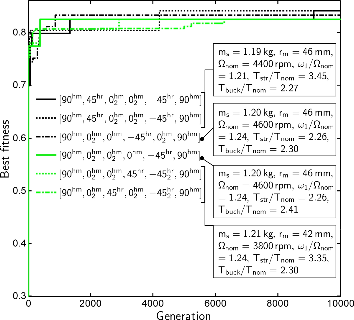
Subcritical shaft optimisation was first studied with the GA. The case of two single-carbon fibre/epoxy composites (BE and HM) and one hybrid case (HM/HS) was examined (see Table 1 for the properties of the materials). The optimisation procedure was computed six times with each composites to check that convergence of the GA was reached. The results of the optimisation are shown in Fig. 4 and the properties of the fittest individuals are summarise in Table 7 in each case. Figs. 4a-4d show the fitness function of the highest ranking individual during the evolution (number of generations) in six different populations. The legend gives the properties of the fittest individual in each population at the last generation. The results obtained show that the five conventional shafts can be replaced by three subcritical boron or carbon reinforced epoxy shafts. The algorithm did not find any subcritical solutions with only two shafts. We note that the operating speed was much higher than the first natural torsional frequency in all the solutions.
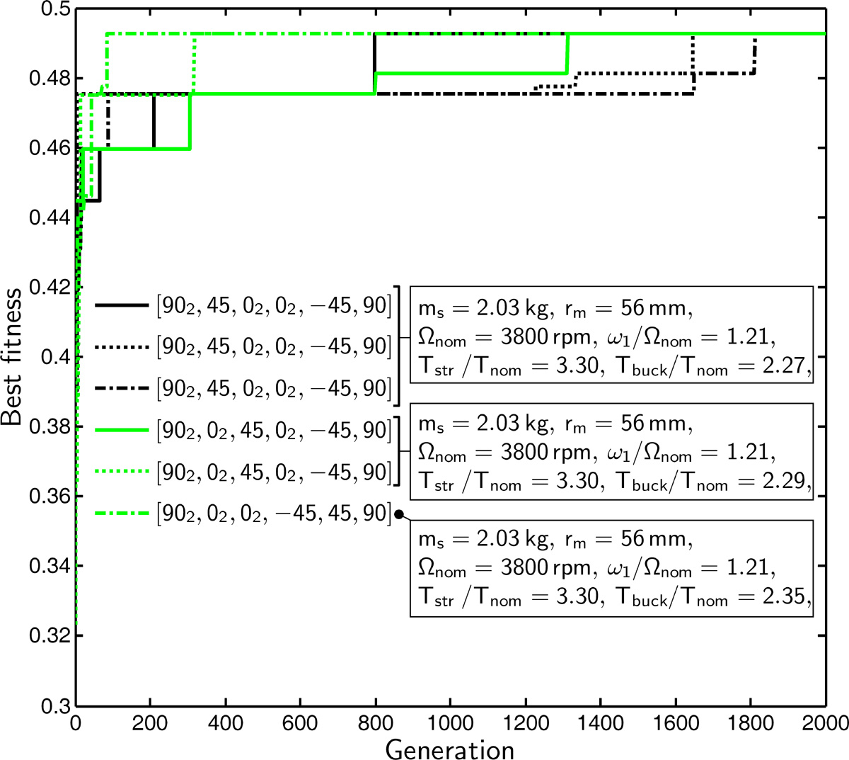
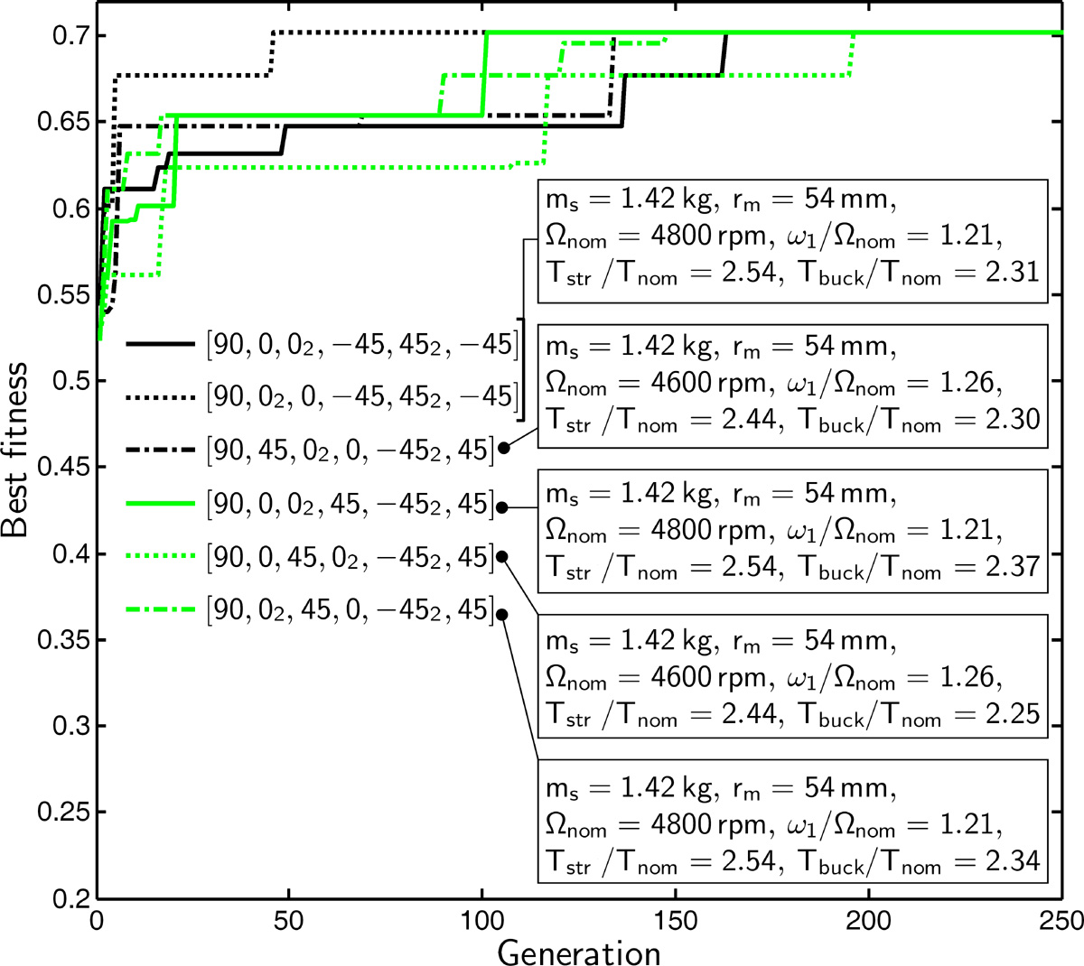
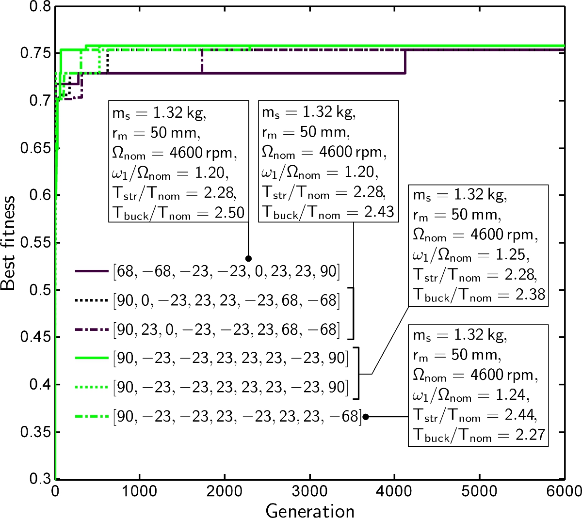
In the BE case (Fig. 4a), GA yielded three different solutions with the same fitness after 2000 generations. All the solutions gave the same radius, the same operating speed and the same plies (three 90° plies, four 0° plies, one -45° ply and one 45° ply) but various stacking sequence orders. They also gave the same critical speeds and the same strength. The independence of critical speed computations from the stacking sequence order is due to EMBT. As far as the strength is concerned, this independence results from in-plane shear loading and the assumption that uncoupled tension-bending is involved (). On the other hand, torsional buckling depends on the stacking sequence order, as shown in Table 4. In particular, the circumferential flexural stiffness of the laminate was found to be highly significant. This explains the position of the 90° plies, which are located in the inner and outer parts of the tube. The solution with the greatest buckling torque was selected as the best individual. The stacking sequence obtained ([90°2, 0°4, 45°, -45°, 90°]) was very similar to that of Zinberg and Symonds’s laminate ([90°, 45°, -45°, 0°6, 90°]), only two 0° plies were replaced here by a 90° ply. The decrease in the shaft thickness and shaft radius explain the slight increase in weight saving from 29% to 30% obtained in comparison with the conventional aluminium shaft (see Table 7). The computing time required for one evolution was approximately equal to one hour using MATLAB [36] on a Xeon E5540.
The second material tested was HM carbon/epoxy (Fig. 4b). Convergence was reached after 200 generations, but five different solutions were obtained with the same fitness. Only the order between 0°, 45° and -45° plies and the operating speed were different. The optimum shaft stacking sequence maximising the strength and buckling margins was [90°, 0°3, 45°, -45°2, 45°]. This gives the minimum thickness authorized (1 mm). Due to the high level of stiffness in comparison with BE, only one 90° ply was necessary to prevent buckling and three 0° plies were required to avoid reaching the first critical speed. The number of 45° plies increased two-fold due to the low strength of HM carbon/epoxy. The weight saving increased considerably in comparison with the previous example, reaching 41% due to several combined effects: the decrease in the density, the mean tube radius, the thickness and the weight of the supports (due to the increase in the operating speed, see Eq. (16)).
The optimisation of the HM carbon/epoxy was then carried out with i.e. {-67.5°, -45°, -22.5°, 0°, 22.5°, 45°, 67.5°, 90°} (Fig. 4c). The chromosome length increased from 24 to 30. This considerably increased the search-space, and hence the number of generations required to obtain convergence and the computing time (approximately 3h/evolution). Convergence was obtained after approximately 6000 generations. Four different optimum individuals were obtained with the same fitness. All of them contained (+ and -)22.5° plies, and most of them contained (+ and/or -)67.5° plies. The optimum shaft selected from four solutions was [90°,-,23°,-23°,,-68°]. This shaft did not contain 0° plies. The weight saving increased slightly in comparison with the previous case, mainly due to the decrease in the mean tube radius.
The last case tested was that of the hybrid HM/HS carbon/epoxy (Fig. 4d). Convergence was again obtained after approximately 6000 generations, despite the fact that only three evolutions yielded the optimum individual. The optimum stacking sequence obtained was [, , , -, ]. This result requires some simple comments. The 90° and 0° plies consisted of HM carbon/epoxy because these plies determine the stiffness problems (the dynamics and buckling). The 45° plies consisted of HS fibres because these plies determine the strength problem. The weight reduction obtained in comparison with the HM case was lower than expected. In fact, the decrease in the weight of the shaft was practically balanced by the increase in the weight of the supports.
The optimisation procedure was also carried out in the case of HS carbon/epoxy material (results not presented here). In the configuration studied here, the HS carbon/epoxy material gave a fitness score in between that obtained with BE and HM composite materials, due to its low density.
In addition, it is worth noting that the number of generations required to converge on the global optimum depended on the size of the search-space, as well as on the basin of attraction of the local and global optima. For example in the case of two materials with the same chromosome length, the number of generations required to reach convergence increased from 250 to 2000 (Figs. 4a-4b).
| Conv. | Lim | ||||||
| Material | aluminium | CEL.[3] | HM | HM/HS | HM/HS | ||
| Number of tubes | - | 5 | 1 | 2 | 2 | 1 | |
| String length | bit | - | - | 27 | 33 | 34 | |
| Stacking sequence | [, | [,, | [,, | [,, | |||
| (from inner to | ° | - | , | ,, | ,, | ] | |
| outer radius) | ]s | ,] | ] | ||||
| Operating speed | rev / min | 5 540 | 6000 | 5 400 | 4 800 | 7 000 | |
| 1st critical speed | rev / min | 8 887 | 490 | 2 696 | 2 647 | 1 018 | |
| 2nd critical speed | rev / min | - | 1 913a | 10 784 | 10 589 | 4 072 | |
| 3nd critical speed | rev / min | - | 4 303a | 24 264 | 23 824 | 9 161 | |
| 4th critical speed | rev / min | - | 7 650a | 43 136 | 42 355 | 16 287 | |
| 1st torsion mode | rev / min | 2 058a | 389a | 1 322 | 409 | 483 | |
| 2nd torsion mode | rev / min | 65 370a | 8 846a | 43 326 | 18 112 | 8 300 | |
| Threshold speed | rev / min | - | -b | 23 658 | 20 356 | 13 638 | |
| Nominal torque | N m | 771 | 712 | 791 | 891 | 610 | |
| Strength torque | N m | 4 925a | 1 492a | 2 439 | 2 096 | 4 352 | |
| Buckling torque | N m | 3 090a | 1 460a | 1 963 | 2 137 | 1 657 | |
| Tube length | m | 1.482 | 7.41 | 3.705 | 3.705 | 7.41 | |
| Mean tube radius | mm | 56.3 | 47.7 | 56.0 | 50.0 | 62.0 | |
| Tube thickness | mm | 1.65 | 1.69 | 1.0 | 1.0 | 1.375 | |
| Support stiffness | kN m-1 | - | -b | 2 864 | 2 864 | 1 437 | |
| Tubes weight | kg (%) | 13.38 | 6.08 (45) | 4.43 (33) | 3.60 (27) | 6.65 (50) | |
| Supports weight | kg | 15.42 | 0 | 3.80 | 4.12 | 0 | |
| Weight penalty | kg | - | 1.5 | 3.0 | 3.0 | 1.5 | |
| Total weight | kg | 28.80 | 7.58a | 11.23 | 10.72 | 8.15 | |
| Weight saving | kg (%) | - | 21.22 (74) | 17.6 (61) | 18.1 (63) | 20.7 (72) | |
a Value computed with presented methods. b Not under consideration in the reference.
4.2 Supercritical shaft optimisation
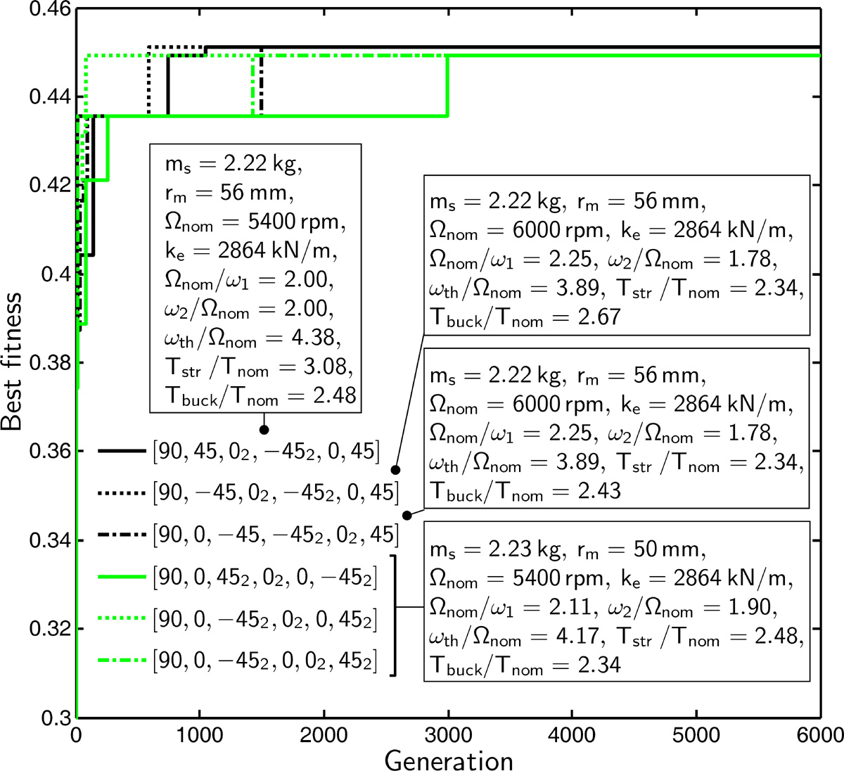
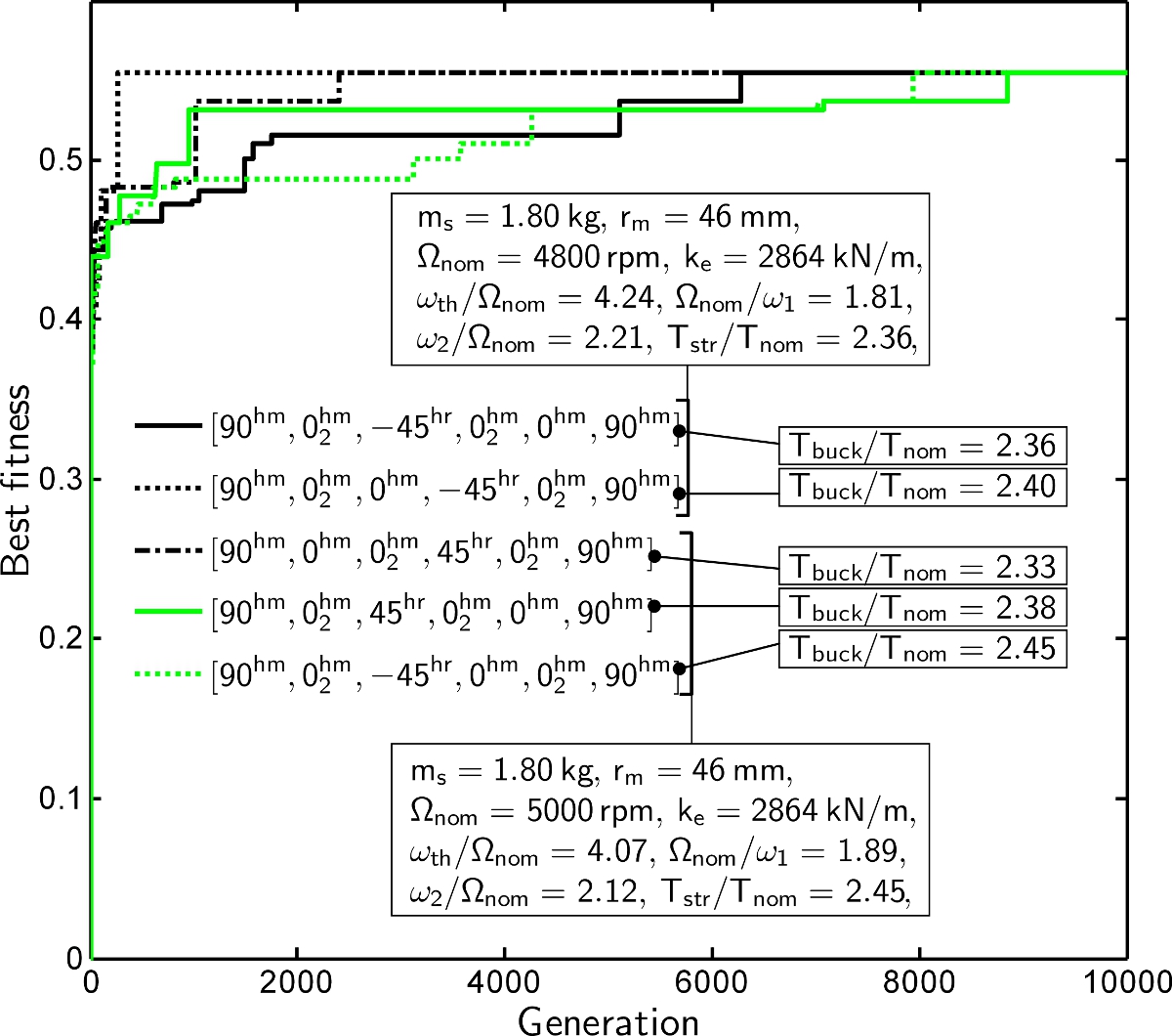
The subcritical condition was then removed. The optimisation was performed in the case of one single-carbon fibre/epoxy composite (HM) and one hybrid composite (HM/HS). The results obtained here show that the five conventional shafts can be replaced by either one or two supercritical shafts (see Table 8 and Figs. 5-6). Contrary to the subcritical optimisation, it was necessary here to take the first four critical speeds and the threshold speed into account. The support stiffness was used as a supplementary optimisation variable to maximise the dynamic stability margin. Lim and Darlow [3] suggested optimising one shaft case with a carbon/epoxy composite denoted here CEL.(Table 1). The latter authors used a generalised reduced gradient method involving continuous variables such as the fraction and the orientation of the laminate plies. Among the stacking sequences tested, [, , , , the optimum one was [, , (Table 8). The operating speed was above the third critical speed and the dynamic stability was not taken into account.
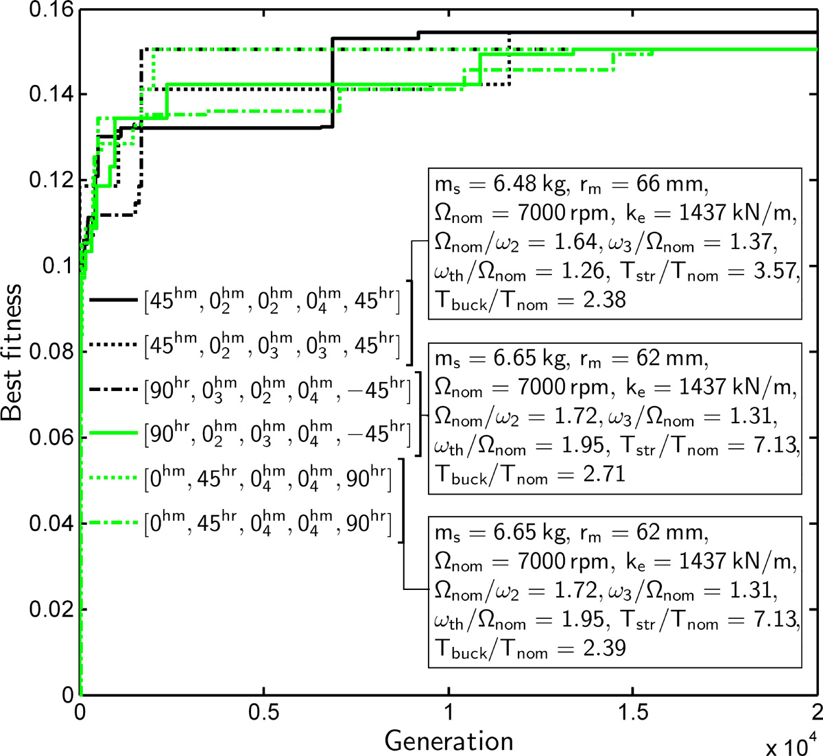
In the two-tube case, the first material studied was HM carbon/epoxy (Fig. 5a). Convergence was reached with three populations after approximately 6 000 generations. The stacking sequence in the optimum shaft (involving larger margins) was , , , ]. This sequence is the same as in the subcritical case, only the order is slightly different. The shaft radius increased from 54 to 56 mm. It can be seen from Fig. 5a that all the margins were particularly large (). In particular, the operating speed was in between the first and second critical speeds, and far above the threshold speed. Much greater weight saving was obtained here than with the conventional aluminium driveline (61%) or the optimum HM subcritical driveline, mainly due to the removal of one intermediate support.
The second case tested was that of the hybrid HM/HS carbon/epoxy (Fig. 5b). Five populations converged onto the optimum fitness after 10 000 generations. All the stacking sequences consisted of five 0° plies made of HM carbon/epoxy, two 90° plies made of HM carbon/epoxy, and one (+ or -)45° ply made of HS carbon/epoxy. The fittest individual was [, , -, , ]. This outcome is similar to that obtained in the subcritical case, only one ply was replaced by one ply. The weight saving obtained was greater than in the HM fibre case, reaching 63%.
In the one-tube case, only hybrid HM/HS carbon/epoxy was studied (Fig. 6). Convergence was reached with five populations after approximately 20 000 generations. The stacking sequence corresponding to the optimum individual was [, , -]. It is worth noting that the number of 0° plies increased considerably in comparison with the two-tube case from 5 to 9, mainly due to the fact that the dynamic constraints had to be achieved. The operating speed here was in between the second and third critical speeds. The AG selected HS fibres for the 90° ply here instead of HM fibres, which is unusual, possibly because the tube thickness was larger than in the previous cases tested, which reduced the buckling risk. The weight saving amounted here to 72%, which is almost equal to that obtained by Lim and Darlow [3]. However, this solution is more efficient because the operating speed was above the second critical speed and the dynamic stability is ensured.
The above optimisation procedure was carried out with . Even after 40 000 generations with 8 populations of 600 individuals, AG did not come up with a better solution. In this case, the computing time was much longer, amounting to approximately 18 hours per population.
5 Conclusion
In this study, some assumptions and simplifications were adopted in order to describe the supercritical motion, the failure strength and the torsional buckling of a CFRP drive shaft sufficiently accurately. The GA presented for optimising supercritical drive shafts was tested on an example previously described in the literature. Analytical models are useful means of obtaining quite reasonable computing times. This example shows the value of CFRP shafts and in particular, that of hybrid CFRP shafts. These solutions make it possible to greatly decrease the number of shafts and the driveline weight under subcritical conditions and even more under supercritical conditions. In most of the cases studied, the following general rules emerged for defining the stacking sequence of hybrid solutions without requiring any optimisation algorithms:
-
1.
45° HS carbon/epoxy plies should be used in order to maximise the torque resistance, in variable proportions ranging between +45° and -45°, depending on the maximum torque direction;
-
2.
0° HM carbon/epoxy plies should be used in order to maximise the axial stiffness and minimise the axial damping involved in bending oscillations;
-
3.
90° HM carbon/epoxy plies should be used far from the shaft middle surface in order to maximise the torsional buckling torque;
-
4.
the laminate does not generally have to be symmetrical.
Appendix A Torsional buckling equations
Equilibrium equations used to solve the torsional buckling problem in the case of a circular cylinder with orthotropic properties:
| (28) |
| (29) |
| (30) |
where and .
Elements of the stiffness matrix in the torsional buckling problem in the case of a very long circular cylinder with orthotropic properties:
| (31) | |||
| (32) | |||
| (33) | |||
| (34) | |||
| (35) |
| (36) | |||
| (37) | |||
| (38) | |||
| (39) |
where .
References
- Zinberg and Symonds [1970] H. Zinberg, M. F. Symonds, The Development of an Advanced Composite Tail Rotor Driveshaft, in: Proceedings of the 26th Annual Forum of the American helicopter Society, Washington, United States, 1970.
- Bauchau [1983] O. A. Bauchau, Optimal design of high speed rotating gaphite/epoxy shafts, Journal of Composite Materials 17 (3) (1983) 170–181.
- Lim and Darlow [1986] J. W. Lim, M. S. Darlow, Optimal sizing of composite power transmission shafting, Journal of the American Helicopters society 31 (1986) 75–83.
- Darlow and Creonte [1995] M. S. Darlow, J. Creonte, Optimal design of composite helicopter power transmission shafts with axially varying fiber lay-up, Journal of the American Helicopters society 40 (2) (1995) 50–56.
- Gubran and Gupta [2002] H. B. H. Gubran, K. Gupta, Composite Shaft Optimization Using Simulated Annealing, Part I: Natural Frequency, International Journal of Rotating Machinery 8 (4) (2002) 275–283.
- Goldberg [1989] D. Goldberg, Genetic Algorithms, Addison Wesley, 1989.
- Awad et al. [2012] Z. Awad, T. Aravinthan, Y. Zhuge, F. Gonzalez, A review of optimization techniques used in the design of fibre composite structures for civil engineering applications, Materials & Design 33 (2012) 534–544.
- Roos and Bakis [2011] C. Roos, C. E. Bakis, Multi-Physics Design and Optimization of Flexible Matrix Composite Driveshafts, Composite Structures 93 (9) (2011) 2231–2240.
- Xu et al. [1991] F.-J. Xu, J.-R. Ye, Y.-D. Xue, Design and Mechanical Analysis of a Hybrid Composite Driveshaft, Composite Structures 9 (1991) 207–216.
- Gubran [2005] H. B. H. Gubran, Dynamics of hybrid shafts, Mechanics Research Communications 32 (4) (2005) 368–374.
- Badie et al. [2011] M. A. Badie, E. Mahdi, A. M. S. Hamouda, An investigation into hybrid carbon/glass fiber reinforced epoxy composite automotive drive shaft, Materials & Design 32 (3) (2011) 1485–1500.
- Lee et al. [2004] D. G. Lee, H. S. Kim, J. W. Kim, J. K. Kim, Design and manufacture of an automotive hybrid aluminum/composite drive shaft, Composite Structures 63 (2004) 87–99.
- Mutasher [2009] S. A. Mutasher, Prediction of the torsional strength of the hybrid aluminum/composite drive shaft, Materials & Design 30 (2) (2009) 215–220.
- Abu Talib et al. [2010] A. Abu Talib, A. Ali, M. Badie, N. Azida Che Lah, A. Golestaneh, Developing a hybrid, carbon/glass fiber-reinforced, epoxy composite automotive drive shaft, Materials & Design 31 (1) (2010) 514–521.
- Hochard et al. [2005] C. Hochard, J. Payan, O. Montagnier, Design and computation of laminated composite structures, Composites Science and Technology 65 (2005) 467–474.
- Montagnier and Hochard [2005] O. Montagnier, C. Hochard, Compression characterization of high modulus carbon fibers, Journal of Composite Materials 39 (2005) 35–49.
- Dutt and Nakra [1996] J. K. Dutt, B. C. Nakra, Stability characteristics of rotating systems with journal bearings on viscoelastic support, Mechanism and Machine Theory 31 (6) (1996) 771–779.
- Montagnier and Hochard [2007] O. Montagnier, C. Hochard, Dynamic instability of supercritical driveshafts mounted on dissipative supports – effect of viscous and hysteretic internal damping, Journal of Sound and Vibration 305 (2007) 378–400.
- Bert and Kim [1995a] C. W. Bert, C. K. Kim, Whirling of composite material driveshafts including bending-twisting coupling and transverse shear deformation, Journal of Vibration and Acoustics 117 (1) (1995a) 7–21.
- Gubran and Gupta [2005] H. B. H. Gubran, K. Gupta, The effect of stacking sequence and coupling mechanisms on the natural frequencies of composite shaft, Journal of Sound and Vibration 282 (1-2) (2005) 231–248.
- Sino et al. [2008] R. Sino, T. N. Baranger, E. Chatelet, G. Jacquet, Dynamic analysis of a rotating composite shaft, Composites Science and Technology 68 (2) (2008) 337–345.
- Timoshenko [1937] S. Timoshenko, Vibration problems in engineering, D. Van Nostrand company, inc., 1937.
- Tsai and Hahn [1980] S. Tsai, H. Hahn, Introduction to composite materials, CRC, 1980.
- Adams [1987] R. D. Adams, Engineering Material Handbook, vol. 1, chap. Damping properties analysis of composites, ASME, 206–217, 1987.
- Montagnier [2005] O. Montagnier, Tubes composites à grande vitesse de rotation : analyses expérimentales et modélisation, Ph.D. thesis, University of Marseille, France, 2005.
- Adams and Bacon [1973] R. D. Adams, D. G. C. Bacon, Effect of fiber orientation and laminate geometry on the dynamic properties of the C.F.R.P., Journal of Composite Materials 7 (1973) 422–428.
- Ni and Adams [1984] R. G. Ni, R. D. Adams, A rational method for obtaining the dynamic mechanical properties of laminae for prediction of the damping of laminated plates and beams, Composites 15 (3) (1984) 193–199.
- Montagnier and Hochard [2006] O. Montagnier, C. Hochard, Experimental investigation of dynamic instability of supercritical driveshafts due to internal damping, in: Proceedings of the 7th IFToMM – Conference on Rotor Dynamics, Vienna, Austria, 2006.
- Tsai and Wu [1971] S. W. Tsai, E. M. Wu, A general theory of strength of anisotropic materials, Journal of Composite Materials 5 (1971) 58–69.
- Hochard et al. [2009] C. Hochard, S. Miot, N. Lahellec, F. Mazerolle, M. Herman, J. Charles, Behaviour up to rupture of woven ply laminate structures under static loading conditions, Composites Part A 40 (8) (2009) 1017–1023.
- Hayashi [1975] T. Hayashi, Optimization of the Torsional-Rigidity and Strength for Fiber Reinforced Composite Cylinders, in: Proceedings of the Conference on Composite Materials, vol. 1, 703–724, 1975.
- Flügge [1973] W. Flügge, Stresses in shells, Springer-Verlag, Berlin, 2nd edn., 1973.
- Bert and Kim [1995b] C. Bert, C.-D. Kim, Analysis of buckling of hollow laminated composite drive shaft, Composites Science and Technology 53 (1995b) 343–351.
- Hibbitt and Sorensen [2001] K. Hibbitt, I. Sorensen, ABAQUS/Standard: User’s Manual, Hibbitt, Karlsson & Sorensen, 2001.
- Bauchau et al. [1988] O. A. Bauchau, T. M. Krafchack, J. F. Hayes, Torsional Buckling Analysis and Damage Tolerance of Graphite/Epoxy Shafts, Journal of Composite Materials 22 (1988) 258–270.
- The MathWorks [1990] The MathWorks, MATLAB, The MathWorks Inc., http://www.mathworks.com, 1990.