Emission properties of an oscillating point dipole from a gold Yagi-Uda nanoantenna array
Abstract
We investigate numerically the interaction of an oscillating point dipole with a periodic array of optical Yagi-Uda nanoantennas in the weak coupling limit. A very strong near-field enhancement of the dipole emission by the resonant plasmon mode in the feed element is predicted in this structure. It is shown that the enhancement strength depends strongly on the dipole position, the direction of the dipole moment, and the oscillation frequency. The radiative intensity of the point dipole from appropriate places next to one feed element may exceed the radiative intensity of an equivalent dipole in free-space by a factor of hundred. In spite of only one director used in each nanoantenna of the array, the far-field emission pattern is highly directed. The radiative efficiency (the ratio of the radiative to the full emission) appears to be around 20%.
pacs:
78.67.-n, 42.60.Da, 73.20.MfNanophotonics has been in the focus of intensive investigations in recent years. One of its numerous areas is the nanoscale controlling of light emission from a single molecule or quantum dot. Promising tools for the realization of this goal are optical nanoantennas Gersen et al. (2000); Li et al. (2007); Hofmann et al. (2007); Kühn et al. (2008); Taminiau et al. (2008); Mohammadi et al. (2008); Li et al. (2009); Sun et al. (2008, 2009); Kinkhabwala et al. (2009); Esteban et al. (2010); Koenderink (2009); Kosako et al. (2010).
Metal antennas are traditionally used for controlling the radiation pattern of electromagnetic wave emission in the radio and microwave frequency range. Though the electromagnetic properties of metals in the optical range differ significantly from that in the radio and microwave range, it seems to be reasonable to use the main concepts of radio antennas in the optical range as well. It has been suggested Li et al. (2007); Hofmann et al. (2007); Taminiau et al. (2008); Li et al. (2009); Kosako et al. (2010) to construct a nanooptical antenna with elements that are arranged as in the radio Yagi-Uda antennas.
Yagi-Uda antenna consists usually of one or two reflectors, one feed element and several directors with appropriately selected scattering phases (reflector and director are slightly detuned inductively and capacitively). As it has been recently shown, the nanoantenna elements can be nanorods Hofmann et al. (2007); Taminiau et al. (2008); Kosako et al. (2010), core-shell Li et al. (2007, 2009) or spherical Koenderink (2009) nanoparticles. All elements scatter the light and the resulting interference forms a highly directed beam along the antenna axis. The size of the elements in such optical Yagi-Uda nanoantennas have to be smaller than the light emission wavelength in free-space. Such optical nanoantennas only work efficiently in narrow frequency domains, where the interaction of the emitter with light is resonantly enhanced because of the excitation of so-called localized plasmons Barnes et al. (2003); Polman (2008) in the nanoantenna elements.
Spontaneous emission is not an intrinsic atomic property, but it depends sensitively on the local density of photonic modes at certain frequencies in a microcavity Purcell (1946); Ford and Weber (1984), or, equivalently, on the local electromagnetic field value at the position of the quantum emitter Kühn et al. (2008); Mohammadi et al. (2008); Esteban et al. (2010). Using resonances, it is possible to increase the local electromagnetic field significantly, and, resultantly, to enhance and redirect the dipole emission. In the case of localized plasmon resonances, the collective excitation of electrons at the plasmon frequency leads to a considerably enhanced emission rate when the point dipole is located in the vicinity of metallic nanoparticles with the appropriate orientation of its dipole moment Taminiau et al. (2008); Sun et al. (2008); Kinkhabwala et al. (2009).
The exact description of photon radiation from the quantum emitter located in some metal-dielectric environment is very complicated. A convenient approximation is a model of an oscillating point dipole. It oscillates with constant frequency and magnitude fixed by the external source (so-called weak coupling limit). In other words, the emission of a current inside an environment with spatially modulated permittivity has to be calculated. This system is now classical and can be described by Maxwell’s equations.
The goal of this paper is to calculate the radiation pattern and emission rate of one oscillating point dipole located in the periodic array of optical Yagi-Uda nanoantennas. Each antenna in the array consists of three rectangular gold elements, director, feed, and reflector. The point emitter is located a few nanometers from the edge of one feed element. To the best of our knowledge, the emission properties of an oscillating point dipole from such a structure have not been investigated yet. The so far investigated structures have been either single Yagi-Uda nanoantennas Li et al. (2007); Hofmann et al. (2007); Taminiau et al. (2008); Li et al. (2009); Kosako et al. (2010), or arrays of simpler spherical shapes Sun et al. (2008). Using arrays of antennas in combination with several emitters with controlled phase difference of oscillation, we can control the emission directivity additionally Dregely et al. (2011), as in phased antenna arrays.
The calculation of the radiation characteristics from oscillating dipoles in two-dimensional photonic crystal slabs can be performed using the method of scattering matrix Whittaker and Culshaw (1999); Taniyama and Notomi (2008). Its main idea is to divide the structure into two parts adjacent to a plane through the dipole, to find the scattering matrices of these parts, and to combine them by considering the boundary conditions at the plane with the dipole. We use the Fourier modal method (FMM) Whittaker and Culshaw (1999); Tikhodeev et al. (2002), which can be improved by the formulation of the correct Fourier factorization rules Li (2003) and adaptive spatial resolution Granet and Plumey (2002), as well as of matched coordinates for more complex metallic shapes Weiss et al. (2009).
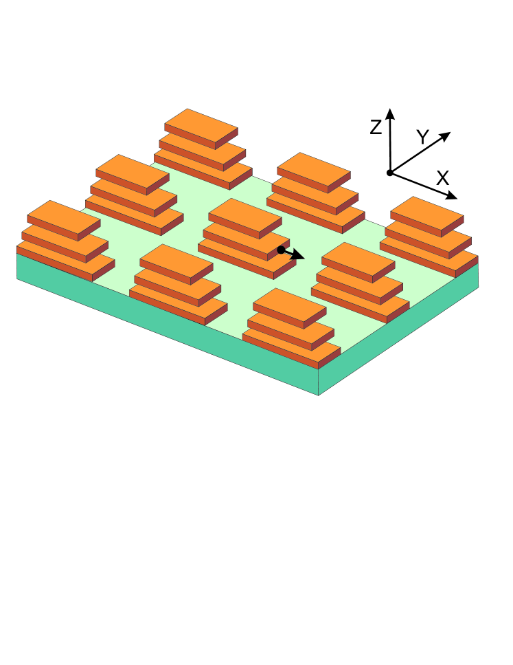
The structure of interest is shown schematically in Fig. 1. It consists of a glass superstrate (), a periodic array of optical Yagi-Uda nanoantennas ordered in a rectangular lattice, and a quartz substrate (). The periods along the - and -axis are equal to 450 nm and 300 nm, respectively. Each antenna consists of three rectangular gold parallelepipeds of 30 nm height and 100 nm width. The lengths of the top (director), middle (feed), and bottom (reflector) elements are 220, 250 and 300 nm, respectively. They are located in glass and the vertical distance between them is equal to 100 nm. We assumed the gold permittivity to be described by the Drude formula with 9016 meV plasma frequency and 81 meV damping rate.
Our first goal is to calculate the directional pattern as well as the emission spectra in the direction normal to the antenna plane. It makes sense to normalize the computed emission intensity , i. e., the Poynting vector of the dipole emission in the far field as a function of the spherical angles and , to the maximum intensity of the emission of a point dipole in free-space, which oscillates with the same magnitude and frequency. Thus, we can easily distinguish the enhancement of emission () from the attenuation () compared to the dipole located in homogeneous vacuum.
To characterize quantitatively the full dipole emission and its radiative part, it is convenient to define the Purcell factor and its radiative part as
| (1) |
respectively. Here, and denote spheres with an infinitely small and large radius, respectively, that surround the point dipole. is the Poynting vector of the dipole emission from the antenna array, is its counterpart for dipole emission in free space. The antenna absorption losses can be characterized by the non-radiative part of the Purcell factor ,
| (2) |
Now, we can also introduce the radiative efficiency indicating the radiative part of dipole emission,
| (3) |
In what follows the results of these quantities will be presented employing 1633 spatial harmonics in the FMM Tikhodeev et al. (2002); Weiss et al. (2009) .
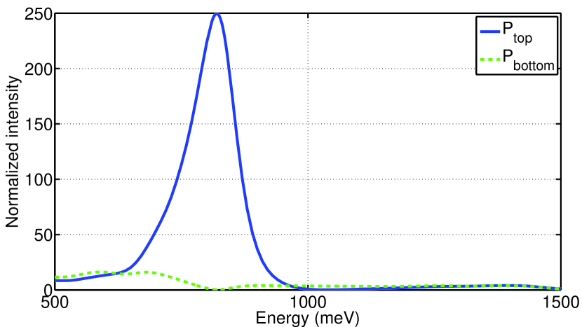
The calculated emission spectra in top () and bottom () directions of the -directed oscillating point dipole located inside the periodic array of gold Yagi-Uda nanoantennas are shown in Fig. 2. The dipole is placed on the horizontal symmetry axis along -direction at a distance of 5 nm to the edge of the feed element (see in Fig. 1). Only one strong and narrow resonance occurs in the emission spectra in the top direction at the photon energy meV (m). Its magnitude is about 250 and the FWHM is 107 meV. The emission to the bottom direction is significantly smaller. It has even a minimum at the plasmon resonance.
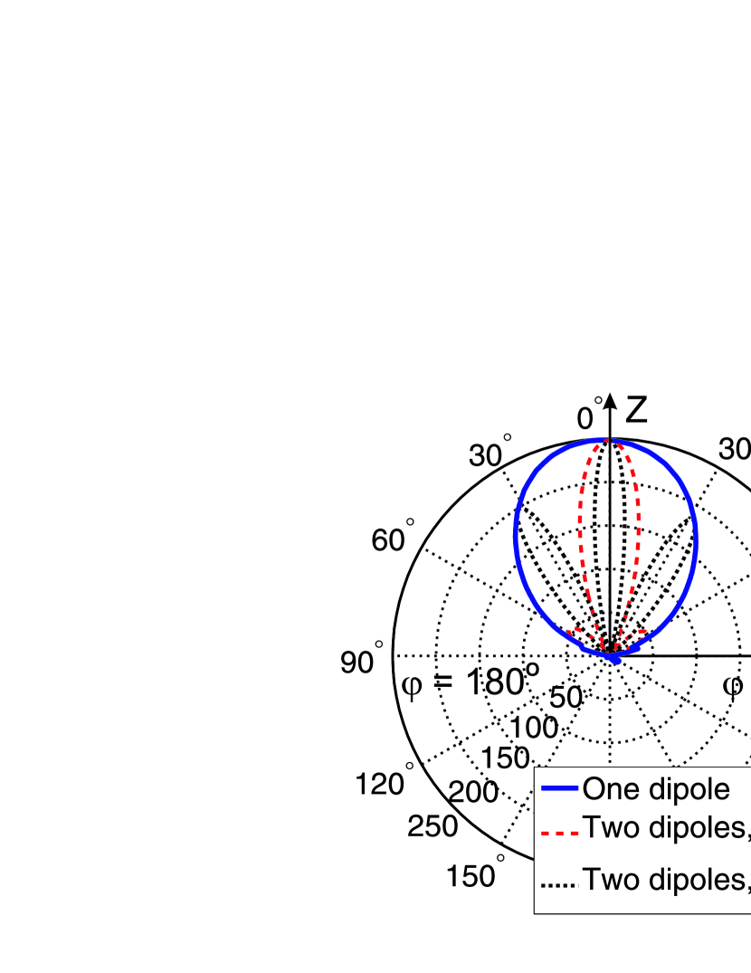
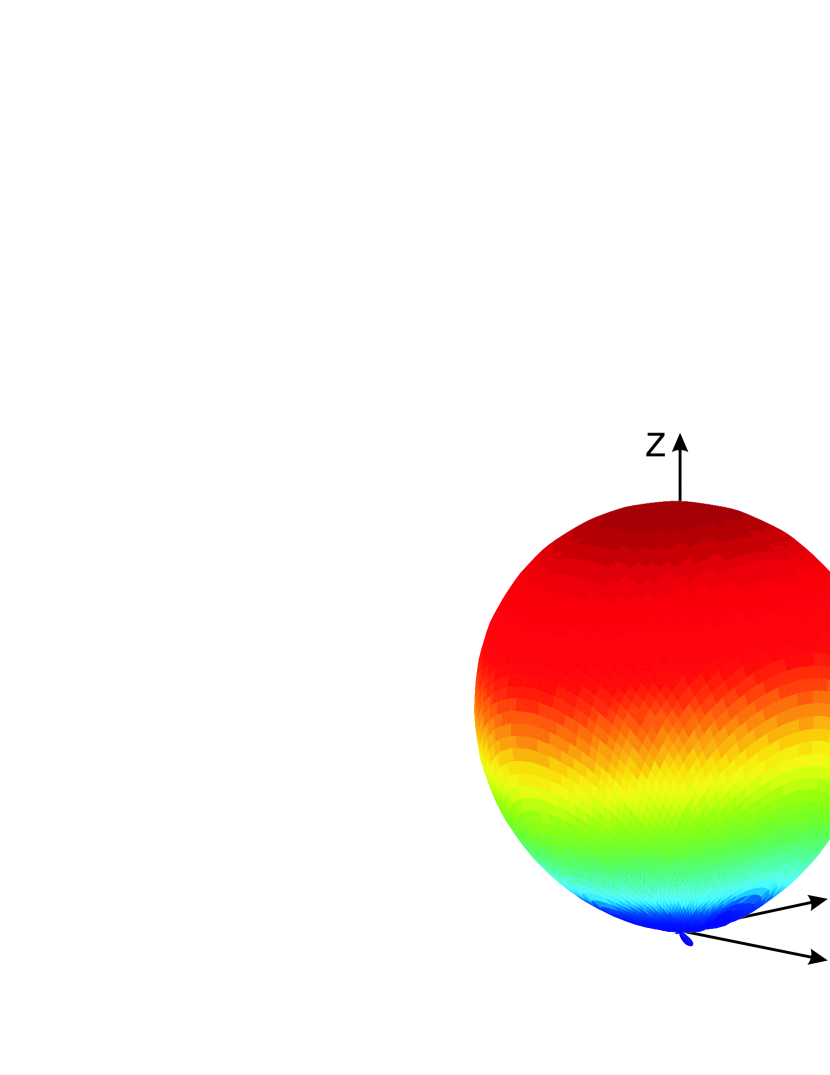
Figure 3 depicts the calculated radiation pattern of emission at the resonant photon energy meV (where is the radial unit vector of a spherical coordinate system centered in the point dipole position). The calculated radiative part of the Purcell factor according to the second Eq. (1) appears to be as high as 80 (see also Fig. 4 below), which indicates a very strong enhancement of the dipole emission by the feed element.
In spite of only one director employed in our Yagi-Uda antenna, the emission in top direction appears to be highly directional. In order to characterize it, the angular directivity can be calculated Balanis (2005), which indicates the part of the full emission radiated along the direction , ,
| (4) |
Its maximum value is called directivity and indicates the antenna’s ability to form a narrow beam. The larger the directivity, the narrower is the light beam. An isotropic radiator would have a directivity of 1, whereas for an oscillating point dipole in free space, . In the case of the radiation pattern of Fig. 3, , i.e., it exceeds the directivity of the dipole in free space by a factor of 3.1. In Taminiau et al. (2008) the directivity of a single Yagi-Uda antenna with three directors has been calculated as 6.4, which is only 1.37 times larger than in our case with only a single director. Furthermore, we can also increase the directivity using more than one dipole emitter coupled to different antenna array elements which is shown below.
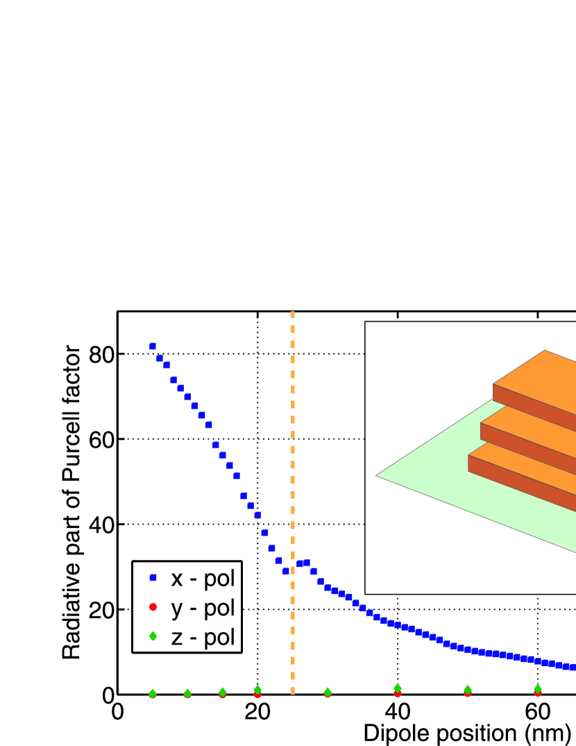
It is also instructive to investigate the dependence of the emission enhancement on the dipole position and on the orientation of its dipole moment respectively to the feed element. Figure 4 shows the calculated dependence of the radiative part of the Purcell factor with respect to the distance between the feed element and the dipole for -, -, and -directed dipoles. The emission enhancement of the antenna array decreases with increasing distance. The strong polarization and distance dependence demonstrates the local nature of the antenna-dipole enhancement.
For the different distances indicated in the inset of Fig. 4, the emission is only significantly enhanced for the -polarized dipole, which means that a plasmon mode with charges oscillating along is excited in the system. Such mode leads to a very strong enhancement of emission and determines the directional pattern. As the electromagnetic field near the edges of the feed element is known to have a dipolar character at the fundamental plasmon mode, it is not surprising that the radiation pattern of the -polarized dipole displaced vertically by 10 nm above the edge of the feed element (see the inset in Fig. 5) nearly coincides with that of the -polarized dipole 5 nm apart from the edge of the feed element (see Fig. 3). Unlike a -polarized dipole in free space, the majority of the emission is directed along the dipole polarization (i.e., along the -axis). The magnitude, however, is about 3 times smaller than that of the x-oriented dipole.
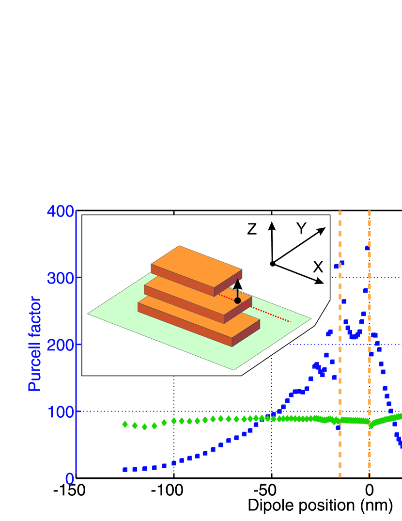
In this point let us discuss the results of the full Purcell factor and the radiative efficiency . The calculated results are shown in Fig. 5, where the dipole is placed 10 nm above the feed (i.e., in a homogeneous transparent glass). The Purcell factor is rather large and reaches the maximum of when the dipole is located above the edge of the feed element. Our numerical analysis shows that the growing oscillations of the calculated Purcell factor when the coordinate approaches the edges of the director, feed, and reflector elements (vertical dashed lines in Fig. 5) are the artifacts of our calculation method. The radiative efficiency appears to be almost independent of the dipole’s -coordinate and is about 20% when the emitter is above the feed element.
It should be mentioned that we omitted the calculation of the full Purcell factor as well as the radiative efficiency in Fig. 4, where the dipole is placed inside a modulated layer. In this case, it appears that we cannot calculate these quantities correctly in the FMM, because the discontinuous permittivity function of such a layer is described by a truncated Fourier expansion. Thus, due to the Gibbs phenomenon, also the non-absorptive surrounding of the metal exhibits a small imaginary part. The point dipole approximation, however, fails if the dipole is placed inside a lossy material.
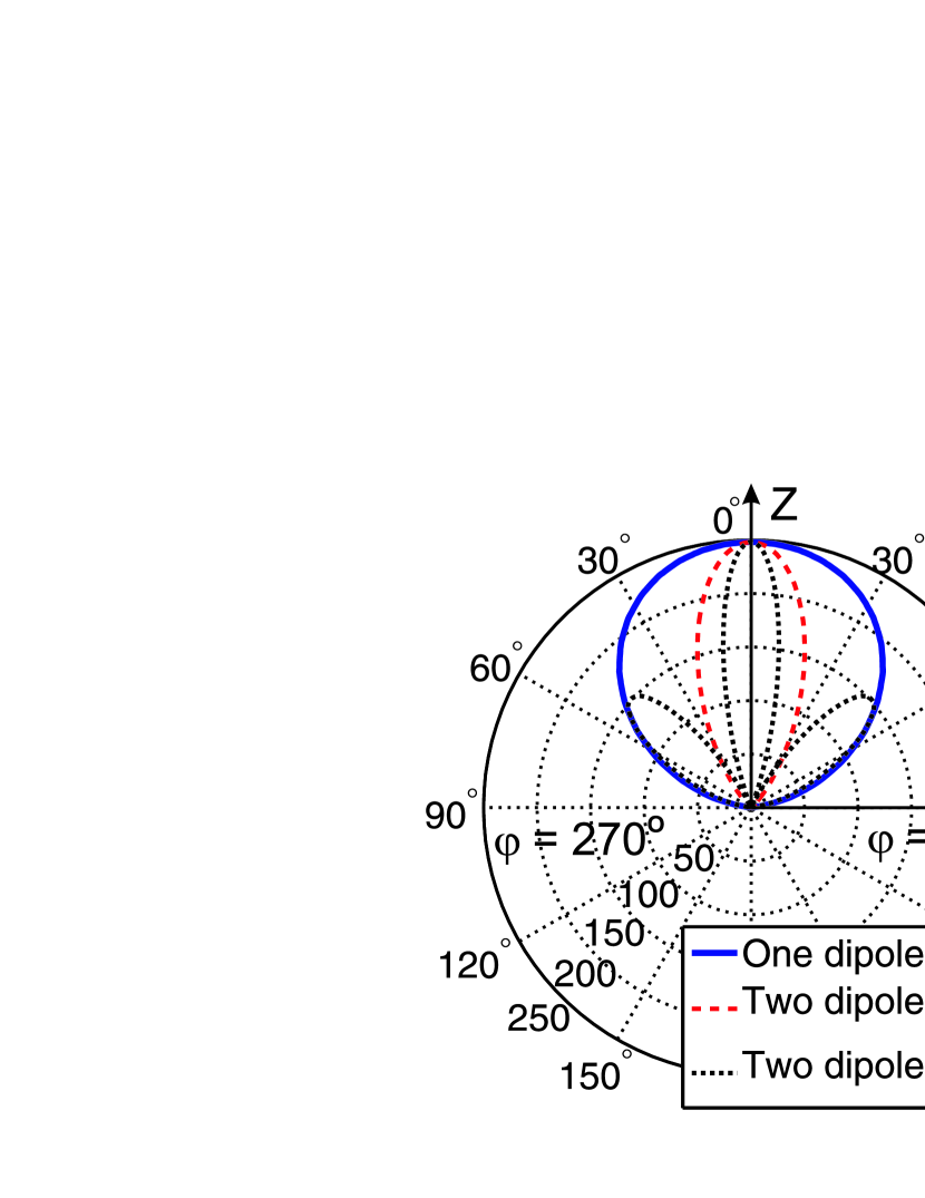
Finally, we would like to mention that the antenna array allows to control the emission directivity further, by using several emitting dipoles in different positions and controlling their phase difference of oscillations. Figure 3 shows the scaled by 2D polar diagrams of the emission of two synchronized dipoles, positioned at neighboring antennas of the array at distance , proportional to integer numbers of periods (see dotted and dashed lines in the left and central panels). The emission intensity of the synchronized pair of dipoles normalized to the maximum emission intensity of two non-synchronized dipoles is then simply , where is the directional pattern of a single dipole (solid line), and is the refractive index of superstrate. Note that the polar diagrams of the synchronized dipoles demonstrate the effect of super-radiance: the Purcell factor of two synchronized closely positioned dipoles becomes twice larger than unsynchronized. It is seen also that it becomes possible to increase the directivity using two emitting dipoles.
To conclude, we show that the gold Yagi-Uda nanoantenna array enhances and simultaneously directs radiation of the oscillating point dipole. The dipole-nanoantenna enhancement depends very strongly on the oscillating frequency, dipole position, and orientation of its moment. It becomes possible to control the emission directivity further by using several synchronized emitting dipoles attached to different antennas in the array. This opens a way to manipulate an excited-state lifetime of a quantum emitter and to fabricate narrow beaming nanoscale antennas in the optical range.
We acknowledge support from BMBF (13N 9155, 13N 10146), DFG (FOR 557, FOR 730, GI 269/11-1), DFH/UFA, ANR Chair of Excellence Program, the Russian Academy of Sciences, and the Russian Foundation for Basic Research
References
- Gersen et al. (2000) H. Gersen, M. F. García-Parajó, L. Novotny, J. A. Veerman, L. Kuipers, and N. F. van Hulst, Phys. Rev. Lett. 85, 5312 (2000).
- Li et al. (2007) J. Li, A. Salandrino, and N. Engheta, Phys. Rev. B 76, 245403 (2007).
- Hofmann et al. (2007) H. F. Hofmann, T. Kosako, and Y. Kadoya, New J. Phys. 9, 217 (2007).
- Kühn et al. (2008) S. Kühn, G. Mori, M. Agio, and V. Sandoghdar, Mol. Phys. 106, 893 (2008).
- Taminiau et al. (2008) T. H. Taminiau, F. D. Stefani, and N. F. van Hulst, Opt. Express 16, 10858 (2008).
- Mohammadi et al. (2008) A. Mohammadi, V. Sandoghdar, and M. Agio, New J. Phys. 10, 105015 (2008).
- Li et al. (2009) J. Li, A. Salandrino, and N. Engheta, Phys. Rev. B 79, 195104 (2009).
- Sun et al. (2008) G. Sun, J. B. Khurgin, and R. A. Soref, J. Opt. Soc. Am. B 25, 1748 (2008).
- Sun et al. (2009) G. Sun, J. B. Khurgin, and R. A. Soref, Appl. Phys. Lett. 94, 101103 (2009).
- Kinkhabwala et al. (2009) A. Kinkhabwala, Z. Yu, S. Fan, Y. Avlasevich, K. Müllen, and W. E. Moerner, Nat. Photon. 3, 654 (2009).
- Esteban et al. (2010) R. Esteban, T. V. Teperik, and J. J. Greffet, Phys. Rev. Lett. 104, 026802 (2010).
- Koenderink (2009) A. F. Koenderink, Nano Lett. 9, 4228 (2009).
- Kosako et al. (2010) T. Kosako, Y. Kadoya, and H. F. Hofmann, Nat. Photon. 4, 312 (2010).
- Barnes et al. (2003) W. L. Barnes, A. Dereux, and T. W. Ebbesen, Nature 424, 824 (2003).
- Polman (2008) A. Polman, Science 322, 868 (2008).
- Purcell (1946) E. M. Purcell, Phys. Rev. 69, 681 (1946).
- Ford and Weber (1984) G. W. Ford and W. O. Weber, Phys. Rep. 113, 195 (1984).
- Dregely et al. (2011) D. Dregely, R. Taubert, J. Dorfmüller, R. Vogelgesang, K. Kern, and H. Giessen, Nat. Comm. 2, 267 (2011).
- Whittaker and Culshaw (1999) D. M. Whittaker and I. S. Culshaw, Phys. Rev. B 60, 2610 (1999).
- Taniyama and Notomi (2008) H. Taniyama and M. Notomi, J. Appl. Phys. 103, 083115 (2008).
- Tikhodeev et al. (2002) S. G. Tikhodeev, A. L. Yablonskii, E. A. Muljarov, N. A. Gippius, and T. Ishihara, Phys. Rev. B 66, 045102 (2002).
- Li (2003) L. Li, J. Optics A 5, 345 (2003).
- Granet and Plumey (2002) G. Granet and J.-P. Plumey, Journal of Optics A: Pure and Applied Optics 4, S145 (2002).
- Weiss et al. (2009) T. Weiss, G. Granet, N. A. Gippius, S. G. Tikhodeev, and H. Giessen, Opt. Express 17, 8051 (2009).
- Balanis (2005) C. A. Balanis, Antenna Theory, 3rd edition (John Wiley & Sons, Hoboken, 2005).