Coherent superconducting quantum pump
Abstract
We demonstrate non-adiabatic charge pumping utilizing a sequence of coherent oscillations between a superconducting island and two reservoirs. Our method, based on pulsed quantum state manipulations, allows to speedup charge pumping to a rate which is limited by the coupling between the island and the reservoirs given by the Josephson energy. Our experimental and theoretical studies also demonstrate that relaxation can be employed to reset the pump and avoid accumulation of errors due to non-ideal control pulses.
Introduction—As electronic circuits are scaled down in size, Coulomb blockade effects Averin86 start to play an important role. This offers the possibility to manipulate individual charges, either single electrons or Cooper pairs. By utilizing the charge degrees of freedom, one can not only demonstrate control at the level of elementary charges but also apply these techniques for practical purposes. In particular, adiabatically operated charge turnstiles Geerligs90 ; Pothier92 and pumps Keller99 are promising candidates for redefining the unit of the ampere in quantum metrology Keller96 . Nevertheless, the minimum current level of 100 pA, required for a so-called quantum metrological triangle experiment Likharev85 , was yet out of reach with these devices. High-frequency operation of charge pumps has been demonstrated in GaAs nanostructures yielding currents of almost 100 pA Blumenthal07 ; Giblin10 , while experimental Pekola08 and theoretical Averin08 studies of a hybrid turnstile promise a satisfactory high yield of 100 pA.
On the other hand, nonadiabatic charge state control has been demonstrated in a number of experiments on superconducting quantum bits (qubits) Nakamura99 ; Pashkin03 ; Yamamoto03 . The manipulation and measurement steps constitute a cycle during which a Cooper pair is coherently transferred through a Josephson junction to an island and then the island is reset to the initial state by incoherent charge transfer through another junction.
Here, we apply nonadiabatic Cooper pair control for coherent charge transfer through a Cooper pair transistor. By applying two sequential -pulses to the device we transfer one Cooper pair from the source to the island and then from the island to the drain resulting in nonvanishing average current through the system. In contrast to already demonstrated adiabatic Cooper pair pumping Niskanen ; Vartiainen ; Mottonen06 ; Mottonen08 , nonadiabatic operation is in principle the fastest way of pumping Cooper pairs and therefore produces the highest pumped current. However, this method induces pumping errors which tend to accumulate from cycle to cycle. The nonideality of the control pulses and dephasing due to background charge fluctuations are the main sources of these errors. Fortunately, we find that by initializing the system after each pumping cycle, the accumulation of errors can be avoided and a pumped dc current is observed. The pumping efficiency of the device, although less than unity, greatly exceeds the efficiency of the recently reported superconducting quantum pump of a different type Giazotto11 .
Theoretical model—The measured devices are based on a Cooper pair transistor that, in addition to the dc gate, has also a pulse gate as shown in Fig. 1. The superconducting island of the transistor (red bar) is separated on one side by a single junction with Josephson energy and on the other side by a superconducting quantum interference device (SQUID). The SQUID works effectively as a single junction with a flux-controllable Josephson energy , which allows us to tune by an external magnetic field Tinkham . The left lead of the transistor is grounded and the right lead is biased by a voltage (see Fig. 1). A similar device but with symmetric bias of the leads is analysed in Ref. Maassen91 . We present the Hamiltonian of our system in the form
| (1) |
where the charging energy of the island is given by the capacitance of lead 1 (grounded), of lead 2 (biased), the gate capacitances and , and the self capacitance of the island as . The number operators of the excess Cooper pairs on the island and on lead 2 are expressed with the charge basis of the number of Cooper pairs on the island (), and on lead 2 (). The induced gate charge in units of is given by . The first term in the sum of the Hamiltonian (Coherent superconducting quantum pump) represents the Josephson coupling of the island to lead 1 and the second is coupling between the island and lead 2.
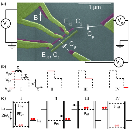
Pumping cycle—The nonadiabatic pumping cycle can be realized with the composite pulse shown in Fig. 1(b) and referred to as the base sequence. Figure 1(c) describes how Cooper pairs are transferred to and from the island during the cycle: First, the electrostatic potential of the island is brought into resonance with the second lead introducing coherent tunneling of a Cooper pair into the island (II). Then the potential is shifted into resonance with the first lead, through which the excess Cooper pair coherently tunnels out (III).
To describe the pumping cycle, we assume that the system with is initialized into state , and that a bias voltage between the leads is applied. We nonadiabatically shift the gate charge from the point (I) which is far away from charge degeneracy to the value (II). At this point, the states and are degenerate and the Hamiltonian (Coherent superconducting quantum pump) reduces to . By choosing the pulse length at this level as , i.e., a -pulse, the initial state changes to by coherent tunneling of a Cooper pair through the second junction. During the second part of the pulse, we nonadiabatically shift the gate charge to (III), where the effective Hamiltonian is , in order to induce coherent oscillations through the first junction. After the interval , the charge state is transferred into (IV). Thus, the charge transfer process induced in the whole cycle is . Repeating the manipulation sequence one can obtain states with any . Hence, ideally one obtains an average dc current of . To pump forward, i.e., along the bias voltage, we can reverse the order of the pulse heights and , which results in transferring a Cooper pair from lead 1 to lead 2. In our experiments, gating errors prevent us from making many repetitions, and the true pumped current is determined by the waiting time in between the pulse sequences as discussed in the following.
Experimental methods—The device is fabricated by two-angle evaporation of Al with a thickness of 10 nm for the island (red patterns in Fig. 1) and 40 nm for the leads (yellow patterns in Fig. 1) on an oxidized silicon substrate using a standard trilayer resist structure. The pattern is defined by electron-beam lithography in the top polymethylmetacrylate resist and then transferred into a Ge layer by reactive ion etching. The lead and gate electrodes are connected via filtered twisted-pair dc lines to room-temperature electronics for biasing and current amplification. The pulse gate is connected to the central line of the prefabricated gold-patterned on-chip coplanar waveguides. The waveguide is ribbon bonded to a coaxial line attenuated by 20 dB at 4 K. Composite pulses are generated by superimposing two channels of a picosecond pulse pattern generator. The sample is mounted in vacuum in a dilution refrigerator with a base temperature of about 30 mK. We extracted the following parameter values for the sample studied in this work: , , and eV.
Results—The current through the device without applying the pumping sequence is shown in Fig. 2(a) as a function of the bias voltage and the dc gate-induced charge controlled by . Around , a 2-periodic supercurrent is visible, confirming that our device is not poisoned by quasiparticles. At higher bias voltages Cooper-pair tunneling resonances become energetically allowed, accounting for some of the other features in Fig. 2(a). In particular, the V-shaped regions around the charge degeneracy points originate from resonant tunneling of one Cooper-pair on or off the island. The strong 1e-periodic features at occur at the crossing of two such Cooper-pair tunneling resonances LepThunPRB2008 ; BillPRL2007 .
For Cooper pair pumping, we utilize the two-level base sequence discussed above and shown in Fig. 1(b), but in each cycle we apply subsequent base sequences followed by a waiting period with length at voltage to allow the system to relax back to the ground state. The current through the device with the pumping cycles applied is shown in Fig. 2(b) as a function of the bias voltage and the dc gate-induced charge for , , and the pulse duration . The pulse levels at the pulse generator are V and V. The corresponding dimensionless gate induced charges defined according to (=1,2) are and . In addition to the Cooper-pair tunneling resonance current () observed also without pulses, a positive current peak () and a negative current peak () are observed. For better visibility, a cut along the -axis for is shown in Fig. 2(c). We attribute the positive current peak to a process, in which an excess Cooper pair tunnels coherently to the island from the first lead during the pulse level (see Fig. 1) and then relaxes incoherently to the second lead during the waiting period. According to this interpretation, the positive current peak should appear at a gate-induced charge . We use this relation to find the correspondence between and by measuring the position of the positive current peak as a function of while keeping the bias voltage fixed. We find that V corresponds to . Using this calibration, the expected position of the positive current peak can be calculated as shown by the dashed black line in Fig. 2(b). The good agreement with the experimental data corroborates our interpretation of the transport process giving rise to this peak.
Since the pumping cycle introduced in Fig. 1(b) and (c) produces a negative current, we attribute the negative current peak in Fig. 2(b) to pumping. This claim is supported by the fact, that pumping is effective only when the pulse amplitude corresponds to the difference in the potentials between the leads given by . For V, pumping is therefore expected to be effective at a bias voltage in good agreement with the data in Fig. 2(b), where the positive current peak is visible for all bias voltages but the negative current is peaked near . In addition, the position of the pumping peak should be at close to as observed in the experiment giving further support to our assignment of the negative current peak to pumping. We have repeated the measurements shown in Fig. 2(b) for pulse amplitudes ranging from V to 2 V giving similar results consistent with the interpretation described above (data not shown).
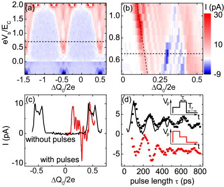
To demonstrate that the Cooper pair pumping is coherent, we measured the pumped current as a function of the pulse length as shown in Fig. 2(d). The bias voltage is set to and the corresponding pulse amplitudes are set to V and V. We obtain a negative current with the base sequence shown in Fig. 1 and a positive current with a similar sequence but with the order of the pulse levels and reversed [insets in Fig. 2(d)]. In both cases, oscillations of the current as a function of the pulse length are observed as expected for the Hamiltonian given in Eq. (Coherent superconducting quantum pump). The oscillations decay on the time scale of hundreds of picoseconds, faster than previously observed in charge qubits Nakamura99 . This decay is dominated by background charge fluctuations which change the resonance condition for the leads, and hence imply rather fast dephasing of the Cooper pair oscillations through the junctions, as confirmed by our numerical simulation of the driven quantum evolution [black line in Fig. 2(d)].
For a Cooper pair pumping sequence, composed of base sequences, the maximal expected current is
given by , since . Thus we characterize the pumping efficiency by
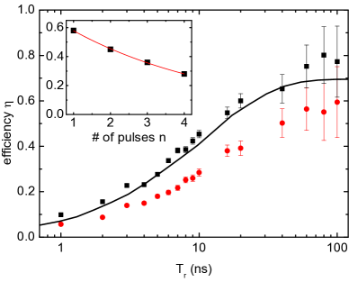
, where is the actual pumped current. In Fig. 3(a), the efficiency
for forward and backward pumping with is shown as a function of . The efficiency for both
directions of pumping approaches exponentially the maximal efficiency
with increasing . This dependence can be phenomenologically described by
, where ns is a characteristic time constant which is of the order of the energy relaxation time found in previous experiments for charge
qubits Astafiev04 . The maximum efficiencies are and for
forward and backward pumping, respectively. Due to the accumulation of pumping errors, this efficiency decreases
for larger of base sequences in a cycle as shown in the inset of Fig. 3 up to for backward
pumping. The maximum efficiency is observed to be proportional to , where
is the efficiency per pulse.
The different efficiencies for forward and backward pumping in Fig. 3 can be
attributed to the finite rise time of the pump pulses. In the case of backward pumping, the energy level of
the island is swept through the degeneracy point resulting in a possible tunneling process of a Cooper pair from the right lead to the island (Fig. 1). Since this process transfers Cooper pairs in the direction of the applied bias voltage, the effective current for the backward pumping is decreased.
Conclusion—We have introduced a device for nonadiabatic Cooper pair pumping and demonstrated its
working principles both theoretically and experimentally. Due to accumulation of pumping errors, the average
pumped current was found to be determined by the internal relaxation rate of the device rather than the
Josephson energy. Although more sophisticated, error correcting, pumping sequences may improve the operation,
it remains to be shown whether nonadiabatic operation provides advantage over adiabatic Cooper pair
pumping Niskanen ; Vartiainen . In future, it would be interesting to study the possible relation between
the geometric phases and the nonadiabatically pumped charge as has been already demonstrated in the adiabatic
case Mottonen06 ; Mottonen08 .
We thank J. Kokkala for discussions. This work was supported by MEXT kakenhi ”Quantum Cybernetics,” the JSPS through its FIRST Program, the European Community’s Seventh Framework Programme under Grant Agreement No. 238345 (GEOMDISS), the Academy of Finland and Emil Aaltonen Foundation.
References
- (1) D. V. Averin and K. K. Likharev, J. Low Temp. Phys. 62, 345 (1986).
- (2) L. J. Geerligs, V. F. Anderegg, P. A. M. Holweg, J. E. Mooij, H. Pothier, D. Esteve, C. Urbina, and M. H. Devoret, Phys. Rev. Lett. 64, 2691 (1990).
- (3) H. Pothier, P. Lafarge, C. Urbina, D. Esteve, and M. H. Devoret, Europhys. Lett. 17, 249 (1992).
- (4) M. W. Keller, A. L. Eichenberger, J. M. Martinis, and N. M. Zimmerman, Science 285, 1706 (1999).
- (5) M. W. Keller, J. M. Martinis, N. M. Zimmerman, and A. H. Steinbach, Appl. Phys. Lett. 69, 1804 (1996).
- (6) K. K. Likharev and A. B. Zorin, J. Low Temp. Phys. 59, 347 (1985).
- (7) M. D. Blumenthal, B. Kaestner, L. Li, S. Giblin, T. J. B. M. Janssen, M. Pepper, D. Anderson, G. Jones, and D. A. Ritchie, Nature Phys. 3, 343 (2007)
- (8) S. P. Giblin, S. J. Wright, J. D. Fletcher, M. Kataoka, M. Pepper, T. J. B. M. Janssen, D. A. Ritchie, C. A. Nicoll, D. Anderson, and G. A. C. Jones, New J. Phys. 12, 073013 (2010)
- (9) J. P. Pekola, J. J. Vartiainen, M. Möttönen, O.-P. Saira, M. Meschke, and D. V. Averin, Nature Phys. 4, 120 (2008).
- (10) D. V. Averin and J. P. Pekola, Phys. Rev. Lett. 101, 066801 (2008).
- (11) Y. Nakamura, Yu. A. Pashkin, and J. S. Tsai, Nature 398, 786 (1999).
- (12) Yu. A. Pashkin, T. Yamamoto, O. Astafiev, Y. Nakamura, and J. S. Tsai, Nature 421, 823 (2003).
- (13) T. Yamamoto, Yu. A. Pashkin, O. Astafiev, Y. Nakamura, and J. S. Tsai, Nature 425, 941 (2003).
- (14) A. O. Niskanen, J. M. Kivioja, H. Seppä, and J. P. Pekola, Phys. Rev. B 71, 012513 (2005).
- (15) J. J. Vartiainen, M. Möttönen, J. P. Pekola, and A. Kemppinen, Appl. Phys. Lett. 90, 082102 (2007).
- (16) M. Möttönen, J. J. Vartiainen, and J. P. Pekola, Phys. Rev. Lett. 100, 177201 (2008);
- (17) M. Möttönen, J. P. Pekola, J. J. Vartiainen, V. Brosco, and F. W. J. Hekking, Phys. Rev. B 73, 214523 (2006).
- (18) F. G. Giazotto, P. Spathis, S. Roddaro, S. Biswas, F. Taddei, M. Governale, and L. Sorba, Nat. Phys. (2011), online only.
- (19) M. Tinkham, Introduction to Superconductivity (Dover, New York, 2004).
- (20) A. Maassen van den Brink, A. A. Odintsov, P. A. Bobbert, and G. Schön, Z. Phys. B: Condens. Matter 85, 459 (1991).
- (21) J. Leppäkangas and E. Thuneberg, Phys. Rev. B 78, 144518 (2008).
- (22) P.-M. Billangeon, F. Pierre, H. Bouchiat, and R. Deblock, Phys. Rev. Lett. 98, 216802 (2007).
- (23) O. Astafiev, Yu. A. Pashkin, Y. Nakamura, T. Yamamoto, and J. S. Tsai, Phys. Rev. Lett. 93, 267007 (2004).