Broadband polarization transformation via enhanced asymmetric transmission through arrays of twisted complementary split-ring resonators
Abstract
This study proposes an ultrathin chiral metamaterial slab stacked with twisted complementary split-ring resonators (CSRRs) for highly efficient broadband polarization transformation. The polarization of linearly polarized electromagnetic waves can be rotated in a specific direction by passing it through such a slab having a thickness of about one-tenth the operational wavelength. Microwave experiments verified the theoretically predicted conversion efficiency of up to 96% covering a bandwidth of 24% of the central wavelength. CSRRs with circular symmetry provide increased interlayer coupling strength, which produces a high-efficiency broadband response and strong isolation of the original polarization.
Metamaterials 1 are potentially useful for tuning the polarization of electromagnetic (EM) waves because they offer myriad ingredients and options beyond conventional EM materials. Two mechanisms in particular, which use either the birefringence effect of anisotropic metamaterials 2 ; 3 ; 4 ; 5 ; 6 ; 7 ; 8 ; 9 ; 10 or the optical activity of chiral metamaterials 11 ; 12 ; 13 ; 14 ; 15 ; 16 ; 17 , can be exploited in the metamaterial regime. More interestingly, an ultrathin metamaterial slab can be used for polarization transformation and perfectly asymmetric transmission without transmission attenuation 9 . However, in previous studies, the novel functionality of ultrathin slabs operated only at a single frequency 3 ; 4 ; 7 ; 8 ; 9 ; 11 ; 12 ; 13 ; 14 ; 15 ; 16 ; 18 . Extension of the operational bandwidth of such a thin polarization transformer is desirable.
A strategy of stacking metallo-dielectric multilayers has been shown to dramatically extend the transmission peak to a broad transparency band when the guided resonance modes of drilled apertures on the metallic layers dominate the enhanced transmission through the multilayered system 19 . Here, a similar scheme consisting of multilayered system containing arrays of twisted complementary split-ring resonators (CSRRs) is proposed for broadband polarization transformation (BPT).
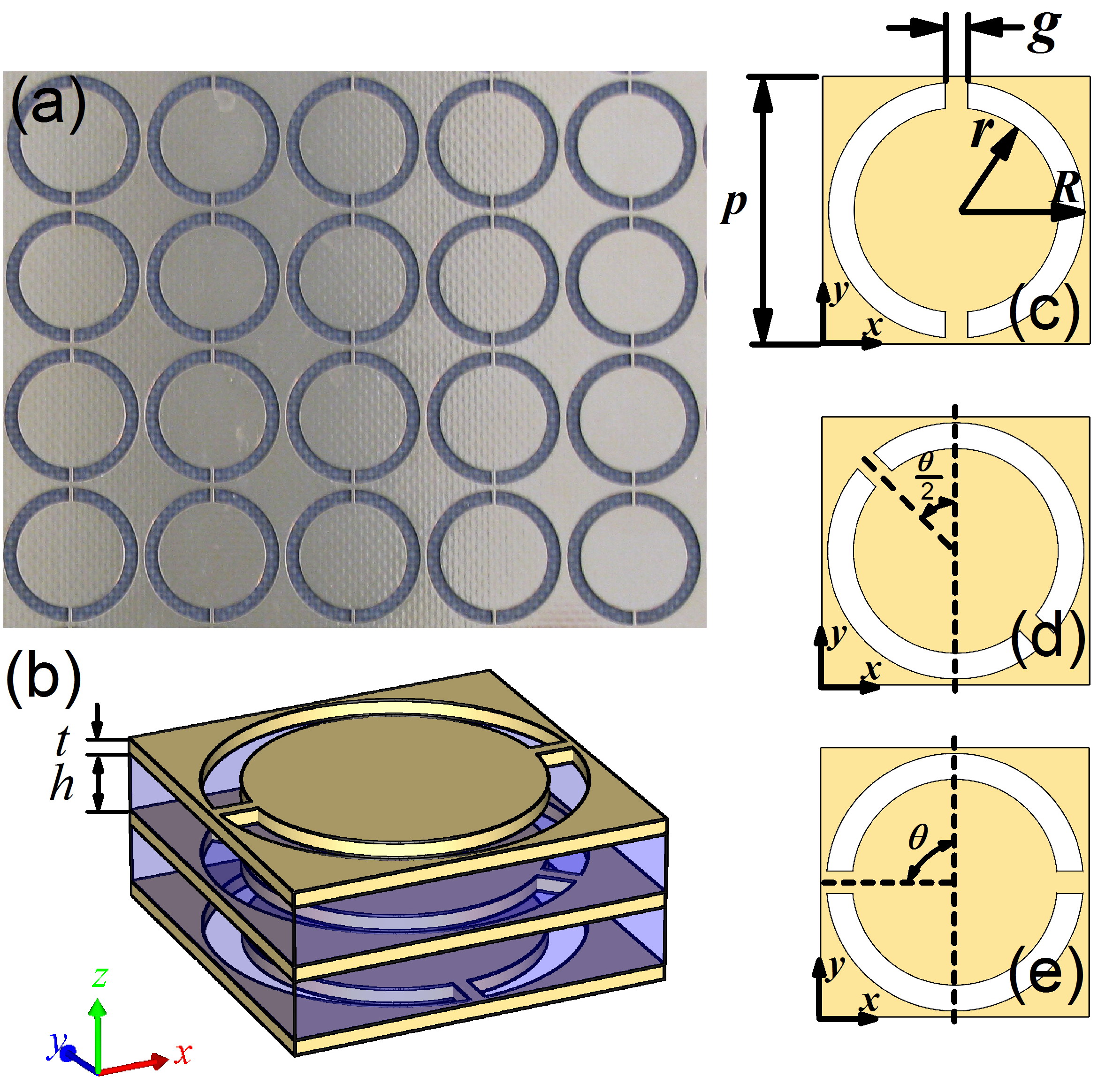
The structure we investigated is comprised of three metallic layers and two dielectric spacer layers. Figures 1(a) and 1(b) present a front-view photo of our sample and the schematic of a unit cell, respectively. The metallic layers lie in the plane; each has a thickness of and is perforated by an array of CSRRs. The dielectric layers each have a thickness of and a dielectric constant of . A CSRR unit is constructed by etching two concentric semi-annular rings through the metallic layer; Figures 1(c)1(e) present front views of the bottom, middle, and top metallic layers, respectively. The rings in a unit are symmetrically segmented by two metallic strips with a width of . The CSRRs have a lattice constant of and inner and outer radii of and , respectively. A unit cell contains three CSRRs aligned along the axis with zero displacement in the plane and arranged from the bottom layer to the top layer with anticlockwise twist angles of = 90o for our sample).
Assuming the metals are perfect electric conductors, we can employ the modal expansion method (MEM) 20 ; 21 ; 22 ; 23 ; 24 ; 25 to semi-analytically solve the transmission and reflection spectra and band structures of the multilayered system. The EM fields within the metallic layers exist only inside the symmetric CSRRs, and the in-plane field components can be rigorously expressed as a series of eigenmodes of the ring apertures. Since the width of the metallic strips is much smaller than both the outer and inner radii (, the eigenmodes inside the CSRRs can be approximated by the transverse electric eigenmodes of a conventional ring aperture as integer orders of Bessel functions 26 . The calculations converge quickly provided that only three lowest eigenmode orders(, and are adopted.
EM waves normally incident on the bottom metallic layer, propagating along the direction, are -polarized along the orientation of the CSRRs (the line across a CSRR’s metallic strips) in the incident plane. The intensity of - or -polarized transmitted waves is defined as , where is the electric field of the incident wave, and is the or component of the electric field of the transmitted waves.
Figure 2(a) presents the calculated and measured transmission spectra. The calculated intensity of -polarized transmitted waves (red dashed line) is less than at all frequencies, whereas that of -polarized transmitted waves (blue solid line) is greater than within a frequency range of 9.812.5 GHz. That is, within this frequency range, the -polarized incident waves are perfectly transformed to -polarized transmitted waves. The bandwidth is about 24% of the central frequency. Within this band, a system having a thickness of about one-tenth the operational wavelength is nearly reflectionless.
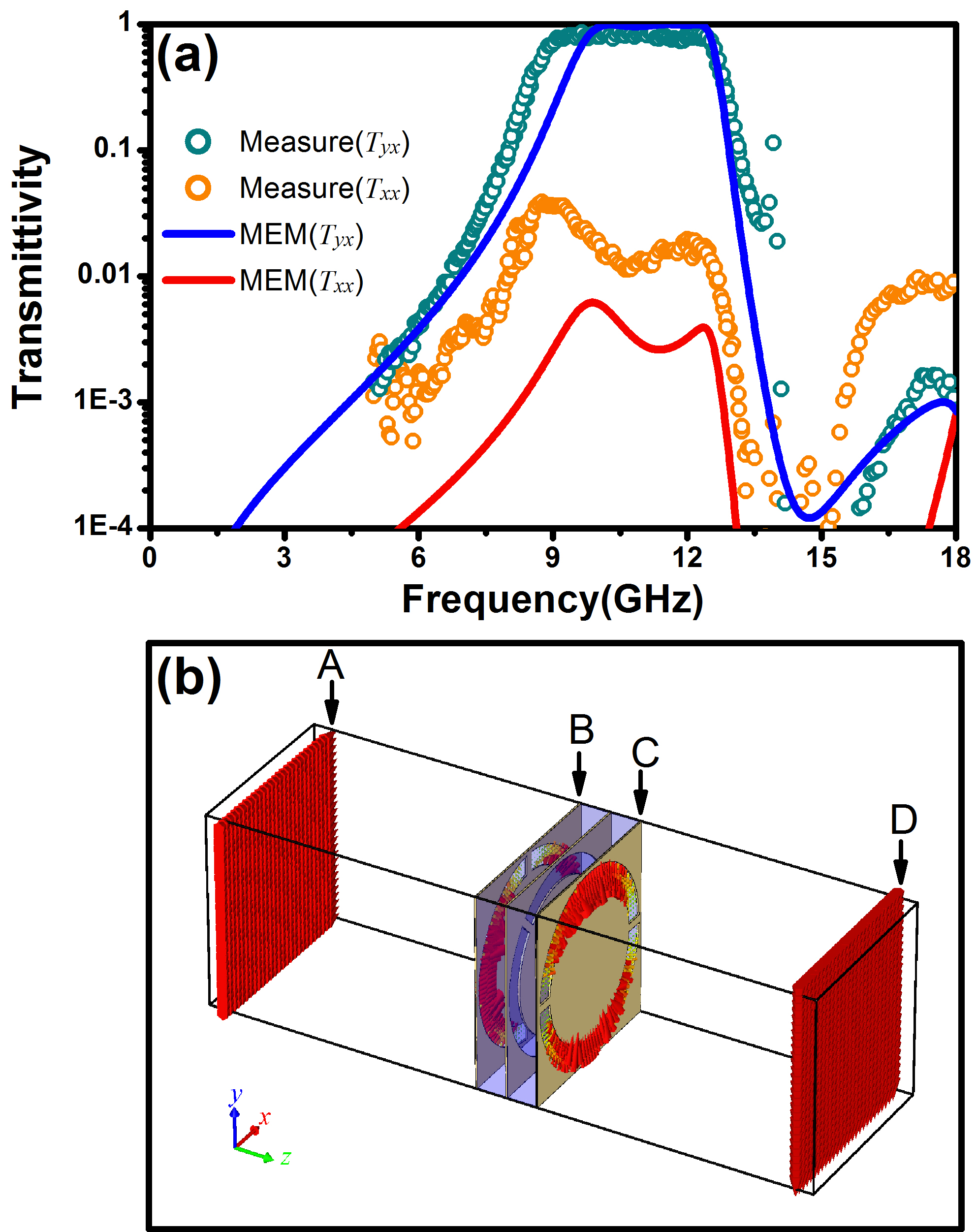
For verification, we fabricated a sample on a printed circuit board with the same structural parameters as the theoretical model. The transmission spectra, taken through the sample plate and measured by a vector network analyzer (Agilent 8722ES), were normalized using the transmission coefficients in free space. The measured results [circles and squares for and , respectively, in Fig. 2(a)] verified the theoretical predictions quite well. The evolution of EM transportation inside the structure was visualized by calculating the spatial field distributions at 11 GHz [Fig. 2(b)]. An -polarized wave incident from the left (Slice A) excites the guided resonant modes of the corresponding CSRRs of the bottom (Slice B), middle, and top (Slice C) metallic layers and finally is perfectly transformed to a -polarized transmitted wave (Slice D). The field distributions in each layer explicitly indicate that the excitation of local resonant modes and interlayer coupling among the twisted CSRRs are crucial to the BPT functionality.
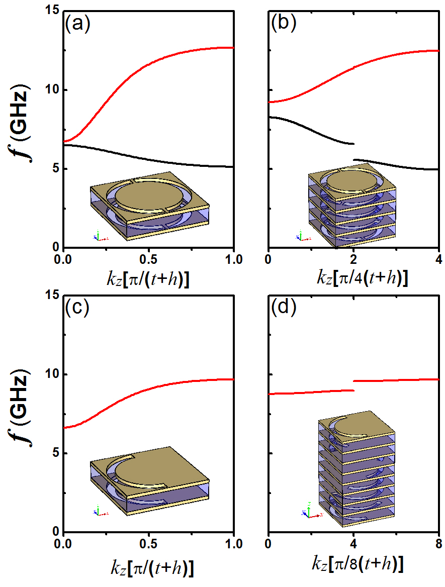
The formation of the broad pass-band (9.812.5 GHz) of can be analyzed heuristically by calculating the band structure of the multilayered CSRR system. The pass-band in Fig. 2(a) precisely falls inside the frequency range with the highest branch in Fig. 3(b) which shows the band structures corresponding to the periodic model [inset, Fig. 3(b)] derived from our twisted model system. In contrast, the periodic model with zero twist angle (, as shown in Fig. 2(a), exhibits a very broad pass-band, as discussed in a previous work [19]. The results shown in Figs. 2(a) and 2(b) can be interpreted in terms of mode coupling and band theory, since the strength of interlayer coupling and resonance hybridization can be quantitatively estimated using the overlap integral of the guided resonance modes of CSRRs on adjacent metallic layers in a unit cell. The strongest near-field coupling occurs between adjacent layers at a twist angle of . Moreover, for a twisted system, the 2-fold circular symmetry of a CSRR maximizes the overlapping regimes where guided resonance modes exist; thus, such a system is also advantageous for its large coupling coefficient, which is crucial to band extension.
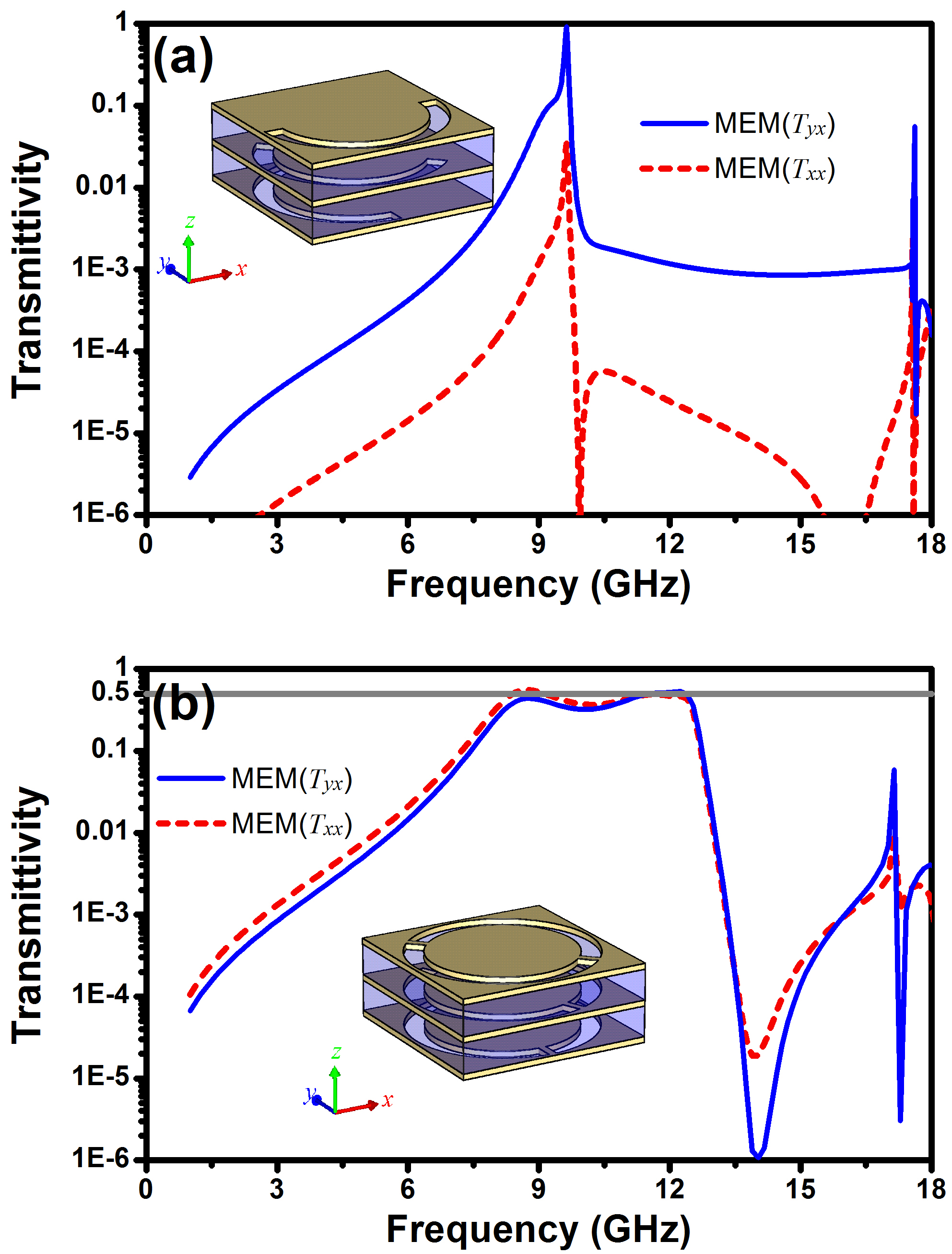
This can be confirmed by control calculations. For instance, let us consider the periodic systems shown in Figs. 3(c) and 3(d). The two systems are derived from those of Figs. 3(a) and 3(b), respectively, by removing one semi-annular ring on each metallic layer in a unit cell. Figures 3(c) and 3(d) show that the corresponding branches (red lines) become much flatter (i.e., cover a much narrower frequency range) than those in Figs. 3(a) and 3(b). The lowest dark band in Fig. 3(a) and the two lowest dark bands in Fig. 3(b) also disappear as the mirror symmetry of the CSRRs is broken. Figure 4(a) shows the and spectra for the model system shown in Fig. 3(d). Perfect polarization transformation happens only at a single frequency. The results further indicate that the circular symmetry of CSRRs, which maximizes the overlapping aperture regimes, is very helpful for enhancing the strength of interlayer coupling as well as the BPT functionality.
Furthermore, we emphasize that the 2-fold mirror symmetry of the CSRRs also ensures that the allowed state propagating through each metallic layer has a single linear polarization along the orientation of the corresponding CSRRs. Our CSRR system can rotate the linear polarization of an incident wave in an arbitrary direction prescribed by the angle . Figure 4(b) shows the transmission spectrum of another sample with a twist angle . The polarization of the incident wave is changed by in a frequency range of 8.512.5 GHz.
In summary, an ultrathin multilayer stacked system containing twisted CSRRs is proposed for manipulating the linear polarization of EM waves and providing asymmetric transmission in a wide frequency range. The polarization rotation is rigorously controlled by the twist angle of the CSRRs at opposite ends of the system. Calculations and experiments both demonstrate that a high conversion efficiency is obtained in a broad frequency range thanks to the excitation and hybridization of the guided resonance modes of CSRRs having circular symmetry. The obtained BPT functionality can be generalized to terahertz, infrared, and visible frequencies for myriad photonic applications.
This work was supported by NSFC (No. 10974144, 60678046), CNKBRSF (Grant No. 2011CB922001), NCET (07-0621), STCSM and SHEDF (No. 06SG24).
References
- (1) D. R. Smith, J. B. Pendry, and M. C. K. Wiltshire, Science 305, 788 (2004).
- (2) J. M. Hao, Y. Yuan, L. X. Ran, T. Jiang, J. A. Kong, C. T. Chan, and L. Zhou, Physical Review Letters 99, 063908 (2007).
- (3) J. Y. Chin, M. Z. Lu, and T. J. Cui, Appl. Phys. Lett. 93, 251903 (2008).
- (4) T. Li, H. Liu, S. M. Wang, X. G. Yin, F. M. Wang, S. N. Zhu, and X. A. Zhang, Appl. Phys. Lett. 93, 021110 (2008).
- (5) R. Singh, E. Plum, C. Menzel, C. Rockstuhl, A. K. Azad, R. A. Cheville, F. Lederer, W. Zhang, and N. I. Zheludev, Phys. Rev. B 80, 153104 (2009).
- (6) J. X. Cao, H. Liu, T. Li, S. M. Wang, T. Q. Li, S. N. Zhu, and X. Zhang, J. Opt. Soc. Am. B 26, B96 (2009).
- (7) B. Zhu, Y. J. Feng, J. M. Zhao, C. Huang, and T. A. Jiang, Appl. Phys. Lett. 97, 051906 (2010).
- (8) C. Menzel, C. Helgert, C. Rockstuhl, E. B. Kley, A. Tunnermann, T. Pertsch, and F. Lederer, Physical Review Letters 104, 253902 (2010).
- (9) J. Han, H. Q. Li, Y. C. Fan, Z. Y. Wei, C. Wu, Y. Cao, X. Yu, F. Li, and Z. S. Wang, Appl. Phys. Lett. 98, 151908 (2011).
- (10) J. Y. Chin, J. N. Gollub, J. J. Mock, R. P. Liu, C. Harrison, D. R. Smith, and T. J. Cui, Opt. Express 17, 7640 (2009).
- (11) A. V. Rogacheva, V. A. Fedotov, A. S. Schwanecke, and N. I. Zheludev, Physical Review Letters 97, 177401 (2006).
- (12) E. Plum, V. A. Fedotov, A. S. Schwanecke, N. I. Zheludev, and Y. Chen, Appl. Phys. Lett. 90, 223113 (2007).
- (13) H. Liu, D. A. Genov, D. M. Wu, Y. M. Liu, Z. W. Liu, C. Sun, S. N. Zhu, and X. Zhang, Phys. Rev. B 76, 073101 (2007).
- (14) T. Q. Li, H. Liu, T. Li, S. M. Wang, F. M. Wang, R. X. Wu, P. Chen, S. N. Zhu, and X. Zhang, Appl. Phys. Lett. 92, 131111 (2008).
- (15) E. Plum, J. Zhou, J. Dong, V. A. Fedotov, T. Koschny, C. M. Soukoulis, and N. I. Zheludev, Phys. Rev. B 79, 121104(R) (2009).
- (16) Y. Q. Ye and S. He, Appl. Phys. Lett. 96, 203501 (2010).
- (17) C. Wu, H. Q. Li, Z. Y. Wei, X. T. Yu, and C. T. Chan, Physical Review Letters 105, 247401 (2010).
- (18) V. A. Fedotov, A. S. Schwanecke, N. I. Zheludev, V. V. Khardikov, and S. L. Prosvirnin, Nano Lett 7, 1996 (2007).
- (19) Z. Wei, Y. Cao, Y. Fan, X. Yu, and H. Li, arXiv:1107.4604v1 (2011).
- (20) P. Sheng, R. S. Stepleman, and P. N. Sanda, Phys. Rev. B 26, 2907 (1982).
- (21) P. Lalanne, J. P. Hugonin, S. Astilean, M. Palamaru, and K. D. Moller, J. Opt. a-Pure Appl. Op. 2, 48 (2000).
- (22) Z. Y. Wei, Y. Cao, J. Han, C. Wu, Y. C. Fan, and H. Q. Li, Appl. Phys. Lett. 97, 141901 (2010).
- (23) Z. Y. Wei, J. X. Fu, Y. Cao, C. Wu, and H. Q. Li, Photonics Nanostruct. 8, 94 (2010).
- (24) Z. Y. Wei, H. Q. Li, Y. Cao, C. Wu, J. Z. Ren, Z. H. Hang, H. Chen, D. Z. Zhang, and C. T. Chan, New J. Phys. 12, 093020 (2010).
- (25) Z. Y. Wei, H. Q. Li, C. Wu, Y. Cao, J. Z. Ren, Z. H. Hang, H. Chen, D. Z. Zhang, and C. T. Chan, Opt. Express 18, 12119 (2010).
- (26) J. D. Jackson, Classical Electrodynamics, Third ed. (Wiley, New York, 1998).