Local gravity measurement with the combination of atom interferometry and Bloch oscillations
Abstract
We present a local measurement of gravity combining Bloch oscillations and atom interferometry. With a falling distance of 0.8 mm, we achieve a sensitivity of with an integration time of 300 s. No bias associated with the Bloch oscillations has been measured. A contrast decay with Bloch oscillations has been observed and attributed to the spatial quality of the laser beams. A simple experimental configuration has been adopted where a single retro-reflected laser beam is performing atoms launch, stimulated Raman transitions and Bloch oscillations. The combination of Bloch oscillations and atom interferometry can thus be realized with an apparatus no more complex than a standard atomic gravimeter.
I Introduction
Gravimeters based on atom interferometry have shown impressive results with record sensitivity () best sens muller ; limit sens gravi syrte and accuracy () gravi peter ; comp gravi syrte . However, a falling distance of at least is required to reach those performances preventing them from being miniaturized and making local gravity measurement. Atomic gravimeters based on Bloch oscillations mesure g biraben ; mesure g tino can measure gravity with an interaction distance of few micrometers but the performances are reduced compared to gravimeters based on atom interferometry. The best Bloch oscillations gravimeter reaches an accuracy of and a sensitivity of with a measurement time of one hour mesure g tino .
In this article, we present an atom gravimeter combining atom interferometry and Bloch oscillations. This scheme allows to associate the sensitivity provided by atom interferometry and the locality provided by Bloch oscillations.
The combination of Bloch oscillations and atom interferometry has already been demonstrated in order to obtain large momentum transfer atomic beam splitter Bloch splitter biraben ; Bloch splitter chu . The use of optical lattices as waveguide and beam splitter for atom interferometry has also been studied theoretically theorie latt interf . In those works, the two arms of the atomic interferometer are guided by different lattices in which Bloch oscillations occur. The combination of Bloch oscillations and atom interferometry has also been demonstrated in the frame of the fine structure constant measurement det st fine biraben . In this experiment, a Ramsey-Bordé interferometer is used. It is characterized by the fact that the two arms are in the same quantum state in the middle of the interferometer. Thus, only one lattice is needed to guide the atoms in the central part of the interferometer.
In this article, we will adapt this previous combination of Bloch oscillations and Ramsey-Bordé atom interferometer for gravity measurements. In the first part, we will present the configuration which we have chosen to combine atom interferometry and Bloch oscillations. We will provide also the expression of the phase of the interferometer. Our experimental set-up will be described in the second part. Then, we will present the gravity measurements. Finally, we will analyze the impact of Bloch oscillations on the contrast of the interference fringes and on the bias concerning gravity measurements.
II Gravimeter scheme combining atom interferometry and Bloch oscillations
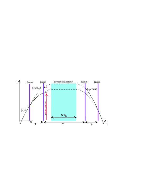
We use a Ramsey-Bordé atom interferometer ramsey borde composed of four Raman laser pulses separated by the times T, T’ and T (see figure 1). The Raman laser drives a transition between the internal state with a momentum and the internal state with a momentum where is the effective wave vector associated with the Raman laser. A pushing beam at resonance with the atoms in the state is applied in the middle of the interferometer. After this step, only atoms in the state remain in the interferometer. If the two photons detuning of the Raman laser is small compare to the Rabi frequency, one can show that the probability to be in the state at the end of the interferometer is :
| (1) |
where the phase of the interferometer is equal to :
| (2) |
where is the radio frequency chirp applied to the Raman laser which compensates the Doppler effect due to gravity acceleration . In this expression, the sign conventions are: when is downward and .
In order to gain sensitivity without increasing the falling distance, the atoms are placed in a laser standing wave between the two pairs of pulses. The standing wave is produced by two counterpropagating laser beams. If one neglects spontaneous emission, the atoms interact with the process of photon absorption from one beam and stimulated emission into the other beam. The result is a change of momentum of the atoms of where is the wave vector of the laser. This process is resonant when the velocity of the atoms relative to the lattice is equal to plus or minus the recoil velocity . Under gravity, the velocity of the atoms decreases until when the atoms become in resonance with the two photons transition. At this point, an adiabatic transition occurs and the velocity of the atoms increases by . This process repeats itself every which is called the Bloch period. This phenomenon where the atom velocity oscillates between and by exchanging photons every with the laser is called Bloch oscillation. This process can be very efficient, 20 000 Bloch oscillations have been experimentally demonstrated Bloch oscillation nagerl . Moreover, the variation of atom velocity which occurs after Bloch oscillations is perfectly known and is equal to .
In the middle of the interferometer, the atoms interact with the Bloch laser beams during a time . After this interaction, the velocity change compared to free falling atoms is equal to leading to an additional phase shift on the interferometer of . A frequency jump of is applied to the Raman frequency in order to keep the Raman laser at resonance with the atoms after the change of velocity produced by the Bloch oscillations. Finally, one obtains for the phase of the interferometer including Bloch oscillations :
| (3) |
The additional phase shift caused by Bloch oscillations is well known because it depends on the laser wavelength and can be canceled experimentally by applying the appropriate frequency jump on the Raman frequency.
In the configuration in which the atoms are launched and then oscillate in a fixed optical lattice (see figure 1), one can increase the scaling factor of the interferometer by increasing without increasing the falling distance. It is therefore possible to have a gravimeter with a scaling factor not limited by the vertical size of the instrument.
III Experimental apparatus
In this part, the whole experimental apparatus is described: the laser source used to manipulate rubidium 87 atoms, the source of cold atom and finally the experimental procedure which combines atom interferometer and Bloch oscillations.
III.1 Laser sources
The laser for trapping, cooling, detecting and pushing the atoms is realized with the frequency doubled fiber bench at 1560 nm described in reference laser onera .
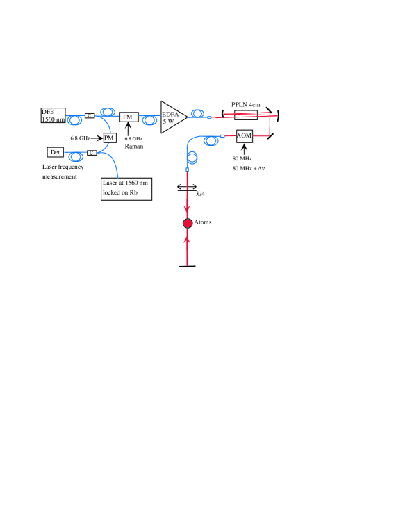
The Raman and Bloch laser are coming out from the same laser source and are also obtained by frequency doubling a fiber bench laser at 1560 nm (see figure 2). A distributed feedback (DFB) laser diode at 1560 nm is amplified in a 5 W erbium doped fiber amplifier (EDFA). Then, the amplified laser is frequency doubled in a periodically poled lithium niobate crystal (PPLN) used in a triple pass geometry. The laser is directed through an acousto-optic modulator (AOM) which controls the intensity of the laser light. The laser beam interacts with the atoms with a waist of 4.5 mm, a circular polarization and a maximum power of 0.2 W. The beam has been collimated with a doublet corrected from abberations. The laser beam is retro-reflected by a mirror placed on a vibration isolation table.
When one wants to address a stimulated Raman transition between the states F=1 and F=2, a radio frequency wave at 6.8 GHz is sent to a fiber phase modulator placed after the DFB laser diode. This modulation creates sidebands at 6.8 GHz on the spectrum of the laser. The radio frequency power is set so that the power ratio at 780 nm between the first sidebands and the central peak is 0.5.
The measurement of the Bloch/Raman laser wavelength is obtained by mixing it with a reference laser at 1560 nm locked on a rubidium transition and by acquiring the beat note with a fast photodiode. The frequency of the beat note is then measured with a 7 GHz spectrum analyzer. In order to measure detuning bigger than 7 GHz, a fiber phase modulator fed with a 6.8 GHz radio frequency wave is inserted on the Raman/Bloch laser. Then, the frequency of the beat note between the reference laser and one of the sidebands of the Bloch/Raman laser is measured. The frequency of the Bloch laser is then given by where is the frequency of the reference laser at 780 nm, is the frequency of the beat note, is the order of the sideband which participates to the beat note and is the frequency of the acousto-optic modulator. With this technique, one can measure the absolute frequency of the Bloch/Raman laser over a large range of detuning (0-60 GHz) and with an accuracy of about 1 MHz, limited by the frequency uncertainty of the reference laser. In the results presented in this article, the Bloch/Raman laser is blue-detuned by 58 GHz from the F=2 F’=2 transition.
III.2 Source of cold atoms and launch with Bloch oscillations
The source of cold atoms is a magneto-optical trap of rubidium 87 loaded from a background vapor. The atoms are then further cooled down in an optical molasses to a measured temperature of . At the end of the optical molasses the atoms are in all the sublevels of the state F=2. A vertical magnetic field of quantification of 60 mG is then applied.
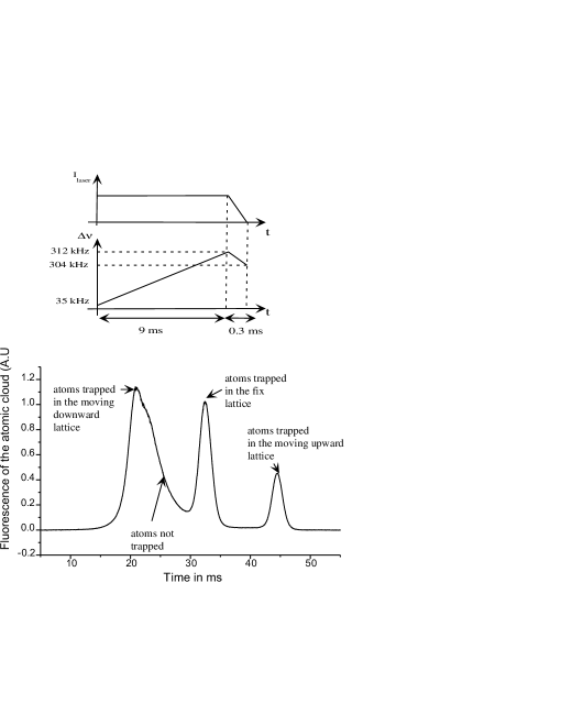
The launch of the atoms is realized with the Bloch laser. For this, two frequencies separated by are applied to the acousto-optic modulator. In this case, the Bloch laser is composed mainly of two frequencies separated by . Thus, the retro-reflected Bloch laser is composed of three standing waves: one fix, one traveling upward at a velocity of and one traveling downward with the opposite velocity. Depending on their velocity, the atoms which interact with this modulated lattice will be trapped in the fix, the moving upward or moving downward lattice. In order to realize the launch of the atoms, the modulated lattice is applied just after the molasses during 9 ms. The frequency is ramped from 35 kHz to 312 kHz in 9 ms. After, the lattice is turn off adiabatically in 0.3 ms. The time of flight signal obtained after this launch procedure is represented on figure 3. We observe clearly three peaks corresponding to atoms trapped in the three different lattices. With this technique, of the atoms are launched at a velocity of 0.12 m/s. The velocity width of the launched atoms is equal to given by the width of the first band of the lattice. For the used lattice depth, only atoms from the first band are trapped.
III.3 Ramsey-Bordé interferometer and Bloch oscillations
After the launch, we apply two Raman pulses which drive a Raman transition from the state to the state . The pulses are separated by the time T and have a duration of . Then, we send a vertical pushing beam which blows the atoms remaining in the state and thus selects the atoms in the state .
When the atoms reach the top of their trajectory, the Bloch laser is turned on adiabatically in . The power of the Bloch laser is set to a point corresponding to a trade off between the losses coming from spontaneous emission which increase with the power and the Landau-Zener losses Bloch Salomon PRA which decrease with the power. This corresponds to a lattice depth of approximately two recoil energy . For this depth, the atoms are only trapped in the first band of the lattice. The atoms in the upper band are not trapped because Landau-Zener losses are too big. The lattice is turned on for a duration of during which Bloch oscillations occur. Our experimental parameters give . The Bloch laser is then turned off adiabatically in . Finally, two other Raman pulses of duration separated by a time T are applied. The total duration of our interferometer is equal to . During this time, the atoms are moving over a distance of .
Finally, we measure the proportion of atoms in the state F=2 and F=1. This step is performed with three pulses of a vertical retro-reflected beam of durations of 2 ms, 0.1 ms and 2 ms. The first and the last pulses are resonant with the F=2F’=3 transition and the middle pulse is resonant with the F=1F’=2 transition and puts the atoms from the state F=1 to the state F=2. The fluorescence of the atoms during the first pulse is proportional to the number of atoms in the state F=2 and the fluorescence collected during the last pulse is proportional to the total number of atoms.
IV Gravity measurement
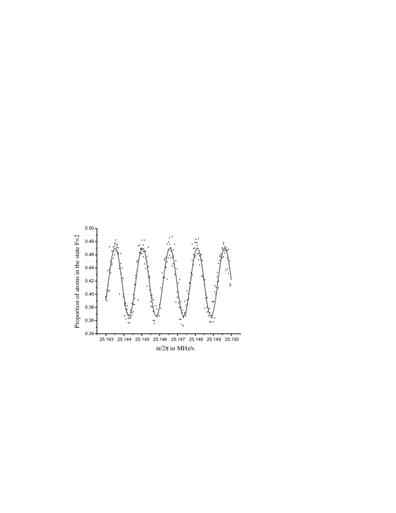
The proportion of atoms in the state F=2 is measured for different values of the radio frequency chirp applied to the Raman frequency. Each measurement takes 1 second corresponding to our experimental cycle time. A typical signal is represented on figure 4. The data are fitted with the function where C is the contrast of the fringes and is the value of the central fringe giving a measurement of gravity. The parameters of the fit are , and . The error bars given in the different results correspond to the error of the fit.
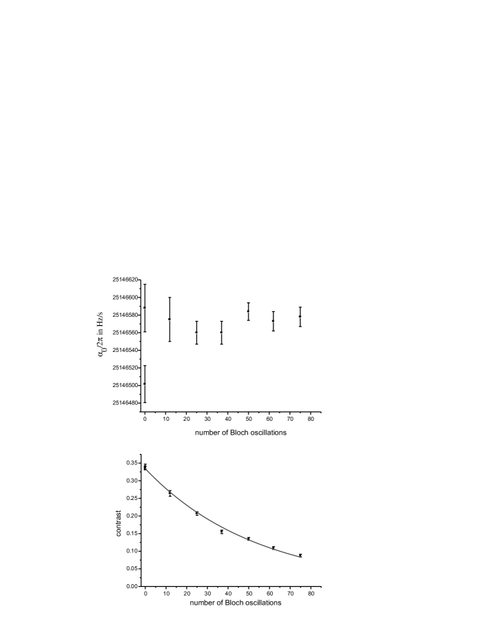
We have measured interference fringes for different number of Bloch oscillations in the lattice. The measurement of the position of the central fringe and the contrast of the fringes are reported on figure 5. One does not note any significant variation of with the number of Bloch oscillations. We can presume that there is no bias associated with the insertion of Bloch oscillations in the interferometer at the level of precision in our experiment. This point will be discussed in details in part V.
However, the contrast of the fringes decreases when the number of Bloch oscillations increase. The decay is well fitted with an exponential function which has a decay constant of . This limitation prevents from increasing significantly the sensitivity of the interferometer with Bloch oscillations because the gain in scale factor is partially compensated by the contrast drop. The best sensitivity (statistical uncertainty given by the fit) obtained is g in 300 s with 75 Bloch oscillations (T’=103 ms) and T=6 ms. Our sensitivity is limited by our detection noise which is equal to (rms value of the noise on the proportion of atoms in the state F=2). The implementation of a better detection system det kasevich should give a better sensitivity with an improvement of at least 10.
V Bias associated with the Bloch oscillations
The insertion of Bloch oscillations in the interferometer is responsible of additional systematic effects compared to an atom interferometer alone. They come from the uncertainty of the Raman frequency jump and from the uncertainty of the velocity variation during the Bloch interaction. An uncertainty on the velocity variation gives an uncertainty on the phase and thus an uncertainty on the gravity measurement . In this part, the different sources of error will be examined. All numerical results will be given for 75 Bloch oscillations () and .
V.1 Uncertainty of the Raman frequency jump
Using equation 3, one obtains that an uncertainty on the Raman frequency jump gives an uncertainty of gravity measurement equal to:
| (4) |
Our radio frequency chain performs the frequency jump with an uncertainty of 0.3 Hz, leading to an error on gravity measurement of g.
V.2 Uncertainty on the laser frequency
The uncertainty on the laser frequency leads to an uncertainty on the recoil velocity and thus an uncertainty on the velocity variation during the Bloch interaction . One obtains finally an uncertainty on the gravity measurement equal to :
| (5) |
In our experiment, the frequency of the Bloch laser is known with an uncertainty of 10 MHz corresponding to the natural drift of the laser between the laser frequency measurement (see III.A) and the gravity measurement. This gives an error on the gravity measurement equal to g. A lock technique easily implementable on our setup can reduce the uncertainty on the laser frequency down to 1 MHz and thus gives an error on gravity of g.
V.3 Nonadiabaticity
Landau-Zener losses and nonadiabaticity in turning off and on the lattice produce atoms with a velocity where is an integer. These atoms have a phase shift equal to which is large compare to for usual time T used in the experiment. This effect can thus give an error on the gravity measurement but can be canceled by choosing a time T multiple of . Experimentally, one did not see any effect by choosing the appropriate T at the level of accuracy of our experiment.
V.4 Gouy phase
The laser beam interacting with the atoms is not exactly a plane wave but a gaussian beam. Thus, due to the Gouy phase, the velocity variation of atoms after the process of absorption and stimulated emission will be not exactly . For atoms located in the waist of the laser beam, one obtains a velocity variation of where is the waist of the laser beam . This leads to a bias on the gravity measurement equal to:
| (6) |
For our experimental parameters, this error is equal to g.
V.5 Longitudinal dipolar electric force of the Bloch beam
The vertical gradient of intensity of the Bloch Beam is responsible of a force changing the velocity of the atoms during the Bloch interaction and thus inducing a bias on the gravity measurement. For a gaussian beam, the intensity varies longitudinally on the distance scale given by the Rayleigh distance which is in our case equal to 82 m. Thus, the order of magnitude of the velocity variation after the Bloch interaction is equal to:
| (7) |
where is the atom mass. The error on gravity measurement is given by:
| (8) |
For our experimental parameters, one obtains g. This error is not negligible and if one wants to reach the level of accuracy of g, the position of the atoms compared to the waist of the Bloch laser should be known precisely in order to obtain a precise estimation of the gradient of intensity. It is also possible to eliminate this systematic effect by noticing that the dipolar force changes sign with the sign of the laser detuning. Measuring gravity with a positive and a negative detuning of the Bloch laser should allow to cancel the effect of the dipolar force.
V.6 Index of refraction
The rubidium gas coming from the vapor background and the cold atomic cloud makes the Bloch beams to propagate in a medium with an index of refraction leading to a slight modification of the recoil velocity. This problem is studied in detail in the reference PRA h sur m . For our experimental parameters, the relative effect on the recoil velocity is approximately equal to which gives an uncertainty on the gravity measurement equal to g.
V.7 Conclusion on the systematic effects
The table 1 gives a summary of the systematic effects coming from Bloch oscillations implementation. The error budget gives a total error of g dominated by the Raman frequency jump. This point can be solved easily with a better radio frequency chain. The other sources of systematic effects show an error around few g dominated by the vertical gradient of intensity.
The measurement of gravity versus the number of Bloch oscillations which indicates no significant dependency with the number of Bloch is compliant with our error budget.
| source | error ( g) |
|---|---|
| Raman frequency jump | 110 |
| Laser frequency | 22 |
| Gouy Phase | 1 |
| Dipolar force | |
| Index of refraction | 1 |
VI Contrast decay associated with the Bloch oscillations
The insertion of Bloch oscillations in the interferometer can induce a contrast decay only via a random velocity variation which gives a random phase . This random velocity variation can come from spontaneous emission or from spatial defaults on the Bloch beams. One can show that the contrast decay is given by the Fourier transform of the distribution probability of velocity variation:
| (9) |
where is the contrast without random velocity jump.
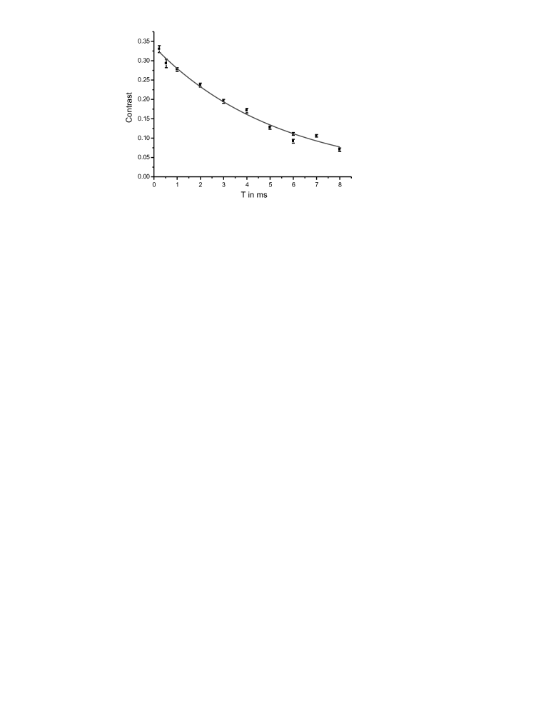
The contrast of our interferometer has been measured versus the time T. The result is plotted on figure 6. The measurements are well fitted with an exponential decay of 5.4 ms time constant. Thus, our experimental data are consistent with a random velocity variation with a Lorentzian probability distribution of FWHM. We will now examine what could be the origin of this random velocity variation.
VI.1 Spontaneous emission
The Bloch beams can interact with the atoms via the process of spontaneous emission. The atoms absorb a photon from one of the lattice beams and emit a spontaneous photon in a random direction. In this process, the velocity of the atoms on the vertical axis can change randomly between . The velocity width of the first band where the atoms are trapped is equal to . Thus, when a spontaneous emission occurs, approximately half of the atoms will remain trapped in the lattice while the others will be lost. The atoms remaining trapped in the lattice will have a random velocity variation with a probability distribution with a width of approximately . Finally, in presence of spontaneous emission, one can show that the contrast will be given by:
where is the rate of spontaneous emission in the lattice, is the proportion of atoms which remain trapped in the lattice after a spontaneous emission and is the probability distribution of the velocity jumps which occur after a spontaneous emission and when the atoms remain trapped in the lattice.
For our experimental parameters (, ), the rate of spontaneous emission is equal to . Thus, the contrast drop is limited to for 75 Bloch oscillations. The contrast decay versus T has a width of approximately . In our experiment, the level of contrast drops and the width of the contrast decay versus T does not correspond to the characteristic of spontaneous emission. We can conclude that the contrast decay observed experimentally does not come from spontaneous emission.
VI.2 Effect of a parasite reflection
Parasite reflections coming from optics on the path of the Bloch beams can interfere with the main beams and thus give interference fringes. These fringes produce a vertical gradient of intensity which leads to a dipolar force which changes the vertical velocity of the atoms and thus gives a phase shift on the interferometer depending on the position of the atoms in the interference fringes. Thus, parasite reflections can lead to a drop of contrast.
In our experiment, the main reflection comes from the window of the vacuum chamber which has a reflection coefficient of per face. This window has an angle of 15 mrad compared to the Bloch beams. The fringes coming from the interference of the Bloch beam and the parasite reflection have a horizontal period of and a vertical period of . The dipolar force exerted on the atoms by the fringes is equal to :
| (11) |
where is the relative depth of the fringe which is in our case approximately 7 %.
The horizontal period of the fringes is small compared to the size of the atomic cloud. Thus, the mean effect of the fringes will be canceled out and the effect of the contrast drop will only remain. For 75 Bloch oscillations (interaction time of 90 ms), one obtains with the force given in the equation (11) a maximum velocity shift of . This effect could thus be responsible of the random velocity variation of deduced from the measurement of the contrast versus T.
We can conclude that fringes on the Bloch beams could explain the contrast decay observed experimentally.
VI.3 Speckle
The laser beam can also be affected by a speckle pattern coming from scattering on optical elements. The speckle pattern is responsible of a dipolar force on the atoms depending on their position in the speckle pattern. Thus, identically to the interference fringes, the speckle can cause a contrast decay.
We will now give the order of magnitude of this effect in our experiment. Scattering from the window of the vacuum chamber which is at a distance of 10 cm from the atoms gives a speckle pattern on the Bloch beam with a horizontal correlation distance of and a vertical correlation distance of . The order of magnitude of the force from the speckle is given by :
| (12) |
where is the relative amplitude of the speckle pattern. For an amplitude of the speckle pattern of and 75 Bloch oscillations, one obtains a velocity variation of . The order of magnitude of this effect corresponds to the velocity variation of deduced from the curve contrast versus T.
The effect of contrast decay with speckle has been confirmed experimentally by the following observations. The contrast has increased by a factor of two for 75 Bloch oscillations and T=6 ms after a careful cleaning of the window of the vacuum chamber. The insertion of a dusty window in the Bloch beam makes the contrast to drop to a level where the fringes can not be observed.
VII Conclusion
In summary, we have presented an experimental demonstration of an atomic gravimeter combining atom interferometry and Bloch oscillations. We have developed a simple experimental setup where one retro-reflected laser beam coming from a unique laser source is performing atom launch, stimulated Raman transition and Bloch oscillations. We reach a sensitivity of g in 300 seconds within a falling distance of 0.8 mm. We did not measure any bias coming from the insertion of Bloch oscillations in the interferometer at our level of sensitivity. Our error budget suggests that the insertion of Bloch oscillations does not prevent from reaching g accuracy level with some improvements on the experimental set-up. Our sensitivity is limited by a contrast decay of the interference fringes coming from the insertion of Bloch oscillations. This contrast decay can be attributed to imperfections of the Bloch beams (fringes and speckle).
With a better beam quality obtainable with tilted windows and better optics, this technique seems very promising to perform high precision local gravity measurements. This technique should allow to make local force measurements with high precision in order for example to test gravity at small distance PRD gravity . This technique should also allow to miniaturize atomic gravimeters.
We thank F. Nez, P. Cladé, S. Guellati-Khélifa and F. Biraben for all fruitful discussions and advices. This work was supported by DGA.
References
- (1) H. Müller, S. W. Chiow, S. Herrmann, S. Chu and K. Y. Chung, Phys. Rev Lett. 100, 031101 (2008).
- (2) J. Le Gouët, T.E. Mehlstäubler, J. Kim, S. Merlet, A. Clairon, A. Landragin and F. Pereira Dos Santos, Appl. Phys. B 92, 133-144 (2008).
- (3) A. Peters, K.Y. Chung and S. Chu, Metrologia 38, 25-61 (2001).
- (4) S. Merlet, Q. Bodart, N. Malossi, A. Landragin, F. Pereira Dos Santos, O Gitlein and L Timmen, Metrologia 47, L9-L11 (2010).
- (5) P. Cladé, S. Guellati-Khélifa, C. Schwob, F. Nez, L. Julien and F. Biraben, Europhys. Lett. 71, 730 736 (2005).
- (6) N. Poli, F.-Y. Wang, M. G. Tarallo, A. Alberti, M. Prevedelli, and G. M. Tino, Phys. Rev. Lett. 106, 038501 (2011).
- (7) P. Cladé, S. Guellati-Khélifa, F. Nez, and F. Biraben, Phys. Rev. Lett. 102, 240402 (2009).
- (8) H. Müller, S. W. Chiow, S. Herrmann, and S. Chu, Phys. Rev. Lett. 102, 240403 (2009).
- (9) T. Kovachy, J. M. Hogan, D. M. S. Johnson, and M. A. Kasevich, Phys. Rev. A 82, 013638 (2010).
- (10) M. Cadoret, E. de Mirandes, P. Cladé, S. Guellati-Khélifa, C. Schwob, F. Nez, L. Julien, F. Biraben, Phys. Rev. Lett. 101, 230801 (2008); R. Bouchendira, P. Cladé, S. Guellati-Khélifa, F. Nez, and F. Biraben, Phys. Rev. Lett. 106, 080801 (2011).
- (11) Ch. J. Bordé, Phys. Lett. A 140, 10 (1989).
- (12) M. Gustavsson, E. Haller, M.J. Mark, J.G. Danzl, G. Rojas-Kopeinig, and H.-C. Nägerl, Phys. Rev. Lett. 100, 080404 (2008).
- (13) O. Carraz, F. Lienhart, R. Charrière, M. Cadoret, N. Zahzam, Y. Bidel and A. Bresson, Appl. Phys. B 97, 405-411 (2009).
- (14) E. Peik, M. Ben Dahan, I. Bouchoule, Y. Castin, C. Salomon, Phys. Rev. A 55, 2989-3001 (1997).
- (15) G.W. Biedermann, X. Wu, L. Deslauriers, K. Takase, and M. A. Kasevich, Opt. Lett. 34, 347-349 (2009).
- (16) P. Cladé, E. de Mirandes, M. Cadoret, S. Guellati-Khélifa, C. Schwob, F. Nez, L. Julien and F. Biraben, Phys. Rev. A 74, 052109 (2006).
- (17) C. D. Hoyle, D. J. Kapner, B. R. Heckel, E. G. Adelberger, J. H. Gundlach, U. Schmidt, and H. E. Swanson, Phys. Rev. D 70, 042004 (2004).