Faraday effect in graphene enclosed in an optical cavity and the equation of motion method for the study of magneto-optical transport in solids

Aires Ferreira1,2, J. Viana-Gomes1, Yu. V. Bludov1, Vitor M. Pereira2, N. M. R. Peres1,2, A. H. Castro Neto2,3 1 Department of Physics and Center of Physics, University of Minho, P-4710-057, Braga, Portugal 2 Graphene Research Centre and Department of Physics, National University of Singapore, 2 Science Drive 3, Singapore 117542 3 Department of Physics, Boston University, 590 Commonwealth Avenue, Boston, Massachusetts 02215, USA
Abstract

We show that by enclosing graphene in an optical cavity, giant Faraday rotations in the infrared regime are generated and measurable Faraday rotation angles in the visible range become possible. Explicit expressions for the Hall steps of the Faraday rotation angle are given for relevant regimes. In the context of this problem we develop an equation of motion (EOM) method for calculation of the magneto-optical properties of metals and semiconductors. It is shown that properly regularized EOM solutions are fully equivalent to the Kubo formula.

pacs:
8.20.Ls, 78.67.Wj, 72.80.Vp, 81.05.ue

I Introduction

Electromagnetic radiation emitted by far stellar objects travels for long periods of time through very diluted concentrations of interstellar gases, traversing regions where week magnetic fields exist. In this circumstance, the polarization of the electric field rotates due to its interaction with the gases immersed in the magnetic field. Due to the enormous traveling distances through such interstellar regions, the degree of rotation of the polarization can be important. This magnetic rotational effect turns out to be a problem in astrophysics, since it modifies, in an unpredictable way, the polarization state of the emitted radiation, introducing additional difficulties in the interpretation of astronomical observations. In the electrodynamics of metals and insulators the effect of polarization rotation induced by a magnetic field was first discussed by FaradayM. Faraday 1846 and, on Earth, has many different applications.

In magneto-optics, the effect coined optical Faraday rotationM. Faraday 1846 refers to the rotation of the plane of polarization of light when it transverses either a dielectricP. R. Berman 2010 or a metal,A. Stern 1964 in the presence of a static magnetic field applied along the direction of propagation of the electromagnetic wave. In addition to the rotation of the plane of polarization, the polarization itself acquires a certain degree of ellipticity. In dielectrics, the effect can be explained using a model of harmonic oscillators coupled to light.P. R. Berman 2010 In metals, the effect has its roots in the Hall effect.Palik 1970

For a two-dimensional (2D) metal, such as graphene, in the Hall regime, the conductivity becomes a tensor Οƒ^^𝜎\hat{\sigma}, with finite (nonzero) values for both diagonal and off-diagonal components. In magneto-optics, the components of the tensor depend both on the frequency of the impinging electromagnetic wave and on the cyclotron frequency of the electrons, due to the magnetic field perpendicular to the plane of the metal. The response of the electrons to the external magnetic field has two regimes: (i) the semiclassical limit, of low fields and/or a high electronic density; and (ii) the quantum Hall regime, of strong fields and/or a low electronic density.

For interpretation of the optical Faraday rotation, in the semi-classical regime, the Drude theory of metals suffices.A. Stern 1964 In the case of graphene, it is possible to change its electronic density either by use of a gate or by the adsorption of molecules.Novoselov 2005 ; Schedin 2007 At high doping, graphene is in the semiclassical regime and Boltzmann transport theory can be used to compute the Hall conductivity.Peres 2007

In the absence of disorder and other relaxation mechanisms (such as electron-phonon scattering), the conductivity of graphene (at zero magnetic field) would be exclusively determined by interband transitions. In the limit of no disorder, the optical conductivity of doped graphene, in the infrared region of the spectrum and at zero magnetic field, is given byPeres 2006 ; Gusynin PRB 2006 ; Carbotte2006_MWresponse ; Ando_UnivCond ; Falkovsky 2007 ; Falkovsky 2 2007 ; Peres IJMP 2008 ; Stauber_VisibleReg

Οƒx​x=Οƒg​nF​(β„β€‹Ο‰βˆ’2​EF),subscript𝜎π‘₯π‘₯subscript𝜎gsubscript𝑛𝐹Planck-constant-over-2-piπœ”2subscript𝐸𝐹\sigma_{xx}=\sigma_{\textrm{g}}n_{F}(\hbar\omega-2E_{F})\,, (1)

where Οƒg=π​e2/(2​h)subscript𝜎gπœ‹superscript𝑒22β„Ž\sigma_{\textrm{g}}=\pi e^{2}/(2h) is the so-called ac universal conductivity of graphene.Peres 2006 ; PeresRMP ; Nair 2008 ; Kuzmenko 2008

When a magnetic field is applied perpendicularly to graphene’s surface, the system develops a finite Hall conductivity. In the quantum regime, it was shown that the Faraday rotation angle ΞΈFsubscriptπœƒπΉ\theta_{F} is solely determined by the fine structure constant α𝛼\alpha, and presents a step-like structure as the Fermi energy crosses different Landau levels (LLs).Morimoto2009 The estimated Faraday rotation steps’ height in this case is of the order of ΞΈF∼0.4∘similar-tosubscriptπœƒπΉsuperscript0.4\theta_{F}\sim 0.4^{\circ},Morimoto2009 a magnitude that can be resolved experimentally.Shimano2008 In the context of topological insulators, similar quantization rules in certain thin-film geometries have been derived in Refs.Β Tse1, and Tse2, . We note in passing that, when the external magnetic field is absent, a dynamic Hall effect can still be induced by using circularly polarized light impinging on graphene at a finite angle with the normal to the graphene surface.Karch

On the theoretical side, the magneto-optical transport properties of graphene have been investigated with the Green’s function methodPeres 2006 ; Gusynin PRB 2006 , and by means of numerical implementations of the Kubo formula, using exact diagonalizationMorimoto2009 and Chebyshev polynomial expansions.Yuan_ResScatt These approaches come with pros and cons: numerical studies allow the exploration of general scenarios, whereas Green’s functions allows one to obtain analytic results, but many times at the expense of lengthy calculations.

Motivated by the need for analytical flexible analytical tools, the equation of motion (EOM) method employed in Ref.Β Peres Excitons, is generalized to include the effect of a magnetic field. As shown later, starting from a small set of EOMs, an adequate treatment permits the derivation of response functions with correct analytical properties (i.e., satisfying Kramers-Kronig causality relations).

The present paper is divided into two main parts. In Sec.Β II we present the EOM method for calculation of the magneto-optical transport in metals and semiconductors; to be concrete, the method is described in the context of the properties of graphene. In Sec.Β III we describe in detail the Faraday effect in graphene and propose an experimental setup that is able to enhance the Faraday effect up to the visible range. SectionΒ III relies heavily on the results derived in Sec.Β II. Some technical details are given in the Appendixes.

We have chosen to organize the subjects according to the following interests of different readers: a reader having a primary interest in the Faraday effect, and familiar with the details on the magneto-optical properties of graphene, should be able to read Sec.Β III with a bird’s-eye reading of Sec.Β II. A reader interested in the Faraday effect in graphene but not well acquainted with its magneto-optical properties may want to go through Sec.Β II first. Finally, reading Sec.Β II alone may appeal to readers interested in applying the EOM method to another problem of interest bearing no relation to graphene.

II Equation of Motion Method for Calculation of the Magneto-Optical Conductivity

Here, we develop the EOM approach to the calculation of the magneto-optical properties of a semiconductor. To be concrete, the method is presented in the context of the optical response of graphene.

Electrons constrained to two dimensions are responsible for a variety of quantum manifestations, a striking example being the integer quantum Hall effect (IQHE). Measured in semiconductor 2D electron gases more than 30 years agovonKlitzing and in the early days of graphene, in both monolayerNovoselov 2005 ; PKim2005 and bilayer samplesNovoselov 2006 (very recently also in trilayer grapheneIQHE_Trilayer ), the static quantum Hall effect is a hallmark of elementary excitations in electronic systems.Thouless_IQHE

Its dynamical analogβ€”the ac quantum Hall effectβ€”can provide additional information about charge carriers, such as the opening of gaps in the spectrum.Carbotte2007 Recent advances in time-domain spectroscopy in the Thz regimeShimano2008 have paved the way to measurement of dynamical optical conductivities at impinging field energies closer to the scale of interest. The goal is to reach cyclotronic energies, usually π’ͺ​(10)π’ͺ10\mathcal{O}(10)Β meV in fields of 1-10 T, where strong optical responses take place. The so-called optical quantum Hall conductivity of 2D electron gases shows a robust plateaux as the Fermi energy is swept, although no quantization rule for the plateaux’s height exists.ShimanoThz Due to its peculiar band structure, graphene has been predicted to display a characteristic optical quantum Hall effect which should be detectable via Faraday rotation measurements.Morimoto2009 In the semiclassical regime, on the other hand, the Faraday rotation of graphene was reported to be π’ͺ​(1)π’ͺ1\mathcal{O}(1) degrees in fields of a few tesla,FaradayNaturePhys a surprisingly high value for a one-atom-thick electronic system.

Refer to caption
Figure 1: Lattice structure and Brillouin zone of monolayer graphene. Left: Hexagonal lattice of graphene, with the next nearest neighbor, 𝜹isubscriptπœΉπ‘–\bm{\delta}_{i}, and the primitive, 𝒂isubscript𝒂𝑖\bm{a}_{i}, vectors depicted. The area of the primitive cell is Ac=3​3​a02/2≃5.1subscript𝐴𝑐33superscriptsubscriptπ‘Ž022similar-to-or-equals5.1A_{c}=3\sqrt{3}a_{0}^{2}/2\simeq 5.1Β Γ…2, and a0≃1.4similar-to-or-equalssubscriptπ‘Ž01.4a_{0}\simeq 1.4Β Γ…. Right: Brillouin zone of graphene, with the Dirac points 𝑲𝑲\bm{K} and 𝑲′superscript𝑲′\bm{K}^{\prime} indicated. Close to these points, the dispersion of graphene is conical and the density of states is proportional to the absolute value of the energy.

II.1 Graphene

The starting point of the present analysis is the low-energy continuum description of single-layer graphene; having two (carbon) atoms per unit cell and sixfold symmetry, its elementary excitations obey a 2D Dirac equation with linear electronic dispersion.CNeto RMP This section is meant to fix the notation. The Brillouin zone of graphene has six corners, and among these, only two are inequivalent, the so-called 𝐊𝐊\mathbf{K} and πŠβ€²superscriptπŠβ€²\mathbf{K}^{\prime} Dirac points (see Fig.Β 1). At these points, the valence and conduction bands touch, with a linear electronic spectrum up to energies of ∼similar-to\sim2Β eV.

We assume, in what follows, that the two Dirac points can be treated independently, and introduce the valley degeneracy index, gv=2subscript𝑔𝑣2g_{v}=2, when pertinent. This consideration is justified for typical experimental conditions (i.e., low concentrations of scattering centers, finite temperatures, etc.) and provides an accurate description of graphene’s electronic transport properties at finite densities.PeresRMP ; Resonant Scatterers

In accordance, we resort to the 2Γ—2222\times 2 Dirac Hamiltonian of graphene, describing the physics of elementary excitations within the 𝐊𝐊\mathbf{K} valley, H𝐊=vFβ€‹πˆβ‹…π©subscriptπ»πŠβ‹…subscriptπ‘£πΉπˆπ©H_{\mathbf{K}}=v_{F}\bm{\sigma}\cdot\mathbf{p}, where vF≃106similar-to-or-equalssubscript𝑣𝐹superscript106v_{F}\simeq 10^{6}m/s is the Fermi velocity, 𝝈=(Οƒx,Οƒy)𝝈subscript𝜎π‘₯subscriptπœŽπ‘¦\bm{\sigma}=(\sigma_{x},\sigma_{y}) [with ΟƒisubscriptπœŽπ‘–\sigma_{i} (i=x,y𝑖π‘₯𝑦i=x,y) denoting Pauli matrices], and 𝐩𝐩\mathbf{p} is the momentum of the low-energy excitation (measured relative to the 𝐊𝐊\mathbf{K} point).CNeto RMP H𝐊subscript𝐻𝐊H_{\mathbf{K}} has eigenvalues given by

E=±ℏ​vF​|𝐀|,𝐸plus-or-minusPlanck-constant-over-2-pisubscript𝑣𝐹𝐀E=\pm\hbar v_{F}|\mathbf{k}|\,, (2)

[with 𝐀=(kx,ky)𝐀subscriptπ‘˜π‘₯subscriptπ‘˜π‘¦\mathbf{k}=(k_{x},k_{y}) denoting a 2D wave vector], and (normalized) wave functions given by

ψλ,𝐀​(𝐫)=12​A​(1λ​ei​θ𝐀)​ei​𝐀⋅𝐫,subscriptπœ“πœ†π€π«12𝐴1πœ†superscript𝑒𝑖subscriptπœƒπ€superscript𝑒⋅𝑖𝐀𝐫\psi_{\lambda,\mathbf{k}}(\mathbf{r})=\frac{1}{\sqrt{2A}}\left(\begin{array}[]{c}1\\ \lambda e^{i\theta_{\mathbf{k}}}\end{array}\right)e^{i\mathbf{k}\cdot\mathbf{r}}\,, (3)

where A𝐴A is the area of the graphene sample, Ξ»=+1πœ†1\lambda=+1(βˆ’11-1) for electron(hole)-like excitation, and θ𝐀=arctan⁑(ky/kx)subscriptπœƒπ€subscriptπ‘˜π‘¦subscriptπ‘˜π‘₯\theta_{\mathbf{k}}=\arctan(k_{y}/k_{x}).

The electromagnetic field can be incorporated via minimal coupling, 𝐩→𝐩+e​𝐀g,→𝐩𝐩𝑒subscript𝐀g\mathbf{p}\rightarrow\mathbf{p}+e\mathbf{A}_{\textrm{g}}, where βˆ’e<0𝑒0-e<0 is the electron charge, and the vector potential 𝐀gsubscript𝐀g\mathbf{A}_{\textrm{g}} relates to the electromagnetic field according to the usual relations, 𝐁=βˆ‡Γ—π€g𝐁bold-βˆ‡subscript𝐀g\mathbf{B}=\bm{\nabla}\times\mathbf{A}_{\textrm{g}} and 𝐄=βˆ’βˆ‚π€g/βˆ‚t𝐄subscript𝐀g𝑑\mathbf{E}=-\partial\mathbf{A}_{\textrm{g}}/\partial t.

Here, the vector potential contains the information about the impinging electromagnetic radiation, and possible external static magnetic fields. Assuming light linearly polarized along the xπ‘₯x axis, the radiation term reads 𝐀=[A0​(𝐫)​eβˆ’i​ω​t+c.c.]β€‹πžπ±π€delimited-[]subscript𝐴0𝐫superscriptπ‘’π‘–πœ”π‘‘c.c.subscript𝐞𝐱\mathbf{A}=[A_{0}(\mathbf{r})e^{-i\omega t}+\textrm{c.c.}]\mathbf{e_{x}}, where Ο‰πœ”\omega stands for the frequency of the radiation field and A0​(𝐫)subscript𝐴0𝐫A_{0}(\mathbf{r}) describes its position dependence. For clarity of exposition, we separate the light-matter interaction term from the free Hamiltonian,

H=H0+e​vFβ€‹πˆβ‹…π€,𝐻subscript𝐻0⋅𝑒subscriptπ‘£πΉπˆπ€H=H_{0}+ev_{F}\bm{\sigma}\cdot\mathbf{A}\,, (4)

where H0≑H𝐊+e​vFβ€‹πˆβ‹…π€Bsubscript𝐻0subscriptπ»πŠβ‹…π‘’subscriptπ‘£πΉπˆsubscript𝐀𝐡H_{0}\equiv H_{\mathbf{K}}+ev_{F}\bm{\sigma}\cdot\mathbf{A}_{B}, with 𝐀Bsubscript𝐀𝐡\mathbf{A}_{B} describing the static magnetic field.

A typical experimental scenario corresponds to a constant magnetic field B>0𝐡0B>0 applied in the transverse direction with respect to the graphene plane. In such case, LLs develop and the eigenenergies of charge carriers become quantized according toMcClure_LandaLev

En=sign(n)ℏ​vFlB2​|n|,n=0,Β±1,Β±2,…,E_{n}=\textrm{sign}(n)\frac{\hbar v_{F}}{l_{B}}\sqrt{2|n|}\quad,n=0,\pm 1,\pm 2,..., (5)

with lB=ℏ/(e​B)subscript𝑙𝐡Planck-constant-over-2-pi𝑒𝐡l_{B}=\sqrt{\hbar/(eB)} denoting the magnetic length. Choosing the gauge 𝐀B=(0,B​x,0)subscript𝐀𝐡0𝐡π‘₯0\mathbf{A}_{B}=(0,Bx,0) results in the following set of Landau eigenfunctions,

ψn,ky​(𝐫)=CnL​(Ο•|n|βˆ’1​(x)i​sign​(n)​ϕ|n|​(x))​ei​ky​y,subscriptπœ“π‘›subscriptπ‘˜π‘¦π«subscript𝐢𝑛𝐿subscriptitalic-ϕ𝑛1π‘₯𝑖sign𝑛subscriptitalic-ϕ𝑛π‘₯superscript𝑒𝑖subscriptπ‘˜π‘¦π‘¦\psi_{n,k_{y}}(\mathbf{r})=\frac{C_{n}}{\sqrt{L}}\left(\begin{array}[]{c}\phi_{|n|-1}(x)\\ i\textrm{sign}(n)\phi_{|n|}(x)\end{array}\right)e^{ik_{y}y}\,, (6)

where Ο•n​(x)=eβˆ’ΞΎβ€‹(x)2/2​Hn​(ξ​(x))/n!​2n​π​lBsubscriptitalic-ϕ𝑛π‘₯superscriptπ‘’πœ‰superscriptπ‘₯22subscriptπ»π‘›πœ‰π‘₯𝑛superscript2π‘›πœ‹subscript𝑙𝐡\phi_{n}(x)=e^{-\xi(x)^{2}/2}H_{n}(\xi(x))/\sqrt{n!2^{n}\sqrt{\pi}l_{B}}, Hn​(x)subscript𝐻𝑛π‘₯H_{n}(x) is the Hermite polynomial of degree nβ‰₯0𝑛0n\geq 0, Ο•βˆ’1​(x)=0subscriptitalic-Ο•1π‘₯0\phi_{-1}(x)=0, and ξ​(x)πœ‰π‘₯\xi(x) stands for the dimensionless center of the Landau orbit, ξ​(x)=lB​ky+x/lBπœ‰π‘₯subscript𝑙𝐡subscriptπ‘˜π‘¦π‘₯subscript𝑙𝐡\xi(x)=l_{B}k_{y}+x/l_{B}. Here, L𝐿L is the linear dimension of the system in the y𝑦y direction and Cnsubscript𝐢𝑛C_{n} is a normalization constant that distinguishes the zero-energy level from the remaining levels, Cn=1subscript𝐢𝑛1C_{n}=1 for n=0𝑛0n=0 and Cn=1/2subscript𝐢𝑛12C_{n}=1/\sqrt{2} for |n|β‰₯1𝑛1|n|\geq 1.

Having reviewed the basics of the graphene’s electronic low-energy theory, in what follows we present the EOM approach to the study of magneto-optical transport.

II.2 Theoretical methods

In the context of electronic systems, the EOM was extensively used in calculations of light polarization in semiconductor laser theory.Koch Recently, it has been used to study excitons in graphene in zero field.Peres Excitons

The EOM approach avoids the calculation of current-current correlators (i.e., Kubo formula), and, hence, provides a shortcut to determination of the response of electronic systems to external perturbations. As shown in detail in AppendixΒ C, with an appropriate regularization procedure, the EOM solutions become fully equivalent to the Kubo formula, and hence provide an accurate description of transport in the linear response regime. Another advantage of the present approach is that it allows for the calculation of non-linear corrections to the conductivity.

At the heart of the EOM approach to calculation of the magneto-optical conductivity is the Heisenberg equation for the electronic current density, 𝑱​(t)𝑱𝑑\bm{J}(t), in the presence of an external electromagnetic field, i.e., d​𝑱/d​t=(i/ℏ)​[H,𝑱]𝑑𝑱𝑑𝑑𝑖Planck-constant-over-2-pi𝐻𝑱d\bm{J}/dt=(i/\hbar)[H,\bm{J}], with H𝐻H being the total Hamiltonian, Eq.Β (4). Having solved for the current density of the system in the presence of external perturbation, in first order in the external field 𝐀𝐀\mathbf{A}, the optical conductivity follows from the constitutive electromagnetic relation

Οƒi​j​(Ο‰)=gs​gvΓ—J~i​(Ο‰)E~j​(Ο‰),subscriptπœŽπ‘–π‘—πœ”subscript𝑔𝑠subscript𝑔𝑣subscript~π½π‘–πœ”subscript~πΈπ‘—πœ”\sigma_{ij}(\omega)=g_{s}g_{v}\times\frac{\tilde{J}_{i}(\omega)}{\tilde{E}_{j}(\omega)}\,, (7)

where O~​(Ο‰)~π‘‚πœ”\tilde{O}(\omega) relates to the average O​(t)𝑂𝑑O(t) [O=Ji,Ej𝑂subscript𝐽𝑖subscript𝐸𝑗O=J_{i},E_{j}] according to O​(t)=O~​(Ο‰)​eβˆ’i​ω​t+c.c.𝑂𝑑~π‘‚πœ”superscriptπ‘’π‘–πœ”π‘‘c.c.O(t)=\tilde{O}(\omega)e^{-i\omega t}+\textrm{c.c.}, with appropriate regularization implicit (AppendixΒ C; Sec.Β II.4). Having graphene in the Dirac cone approximation in mind, the latter equation contains the relevant degeneracies. The spin contribution as a degeneracy factor, gssubscript𝑔𝑠g_{s}, should be valid for typical magnetic fields (≲less-than-or-similar-to\lesssim15 T) when the Zeeman effect does not manifest.

The first step is to project the Heisenberg EOM for the current onto the space of unperturbed single-particle states: we introduce the field operator Ψσ​(𝐫,t)=βˆ‘πœΆc^𝜢,σ​(t)β€‹ΟˆπœΆβ€‹(𝐫)subscriptΞ¨πœŽπ«π‘‘subscript𝜢subscript^π‘πœΆπœŽπ‘‘subscriptπœ“πœΆπ«\Psi_{\sigma}(\mathbf{r},t)=\sum_{\bm{\alpha}}\hat{c}_{\bm{\alpha},\sigma}(t)\psi_{\bm{\alpha}}(\mathbf{r}) (and the respective Hermitian conjugate), where c^𝜢,Οƒsubscript^π‘πœΆπœŽ\hat{c}_{\bm{\alpha},\sigma}(c^𝜢,σ†superscriptsubscript^π‘πœΆπœŽβ€ \hat{c}_{\bm{\alpha},\sigma}^{\dagger}) is the annihilation (creation) operator obeying fermionic anticommutation rules: {c^𝜢,Οƒ,c^πœΆβ€²,σ′†}=Ξ΄πœΆβ€‹πœΆβ€²β€‹Ξ΄Οƒ,Οƒβ€²subscript^π‘πœΆπœŽsuperscriptsubscript^𝑐superscriptπœΆβ€²superscriptπœŽβ€²β€ subscriptπ›ΏπœΆsuperscriptπœΆβ€²subscriptπ›ΏπœŽsuperscriptπœŽβ€²\{\hat{c}_{\bm{\alpha},\sigma},\hat{c}_{\bm{\alpha}^{\prime},\sigma^{\prime}}^{\dagger}\}=\delta_{\bm{\alpha}\bm{\alpha}^{\prime}}\delta_{\sigma,\sigma^{\prime}} and {c^𝜢,Οƒ,c^πœΆβ€²,Οƒβ€²}={c^𝜢,σ†,c^πœΆβ€²,σ′†}=0subscript^π‘πœΆπœŽsubscript^𝑐superscriptπœΆβ€²superscriptπœŽβ€²superscriptsubscript^π‘πœΆπœŽβ€ superscriptsubscript^𝑐superscriptπœΆβ€²superscriptπœŽβ€²β€ 0\{\hat{c}_{\bm{\alpha},\sigma},\hat{c}_{\bm{\alpha}^{\prime},\sigma^{\prime}}\}=\{\hat{c}_{\bm{\alpha},\sigma}^{\dagger},\hat{c}_{\bm{\alpha}^{\prime},\sigma^{\prime}}^{\dagger}\}=0. The symbol 𝜢=(Ξ»,𝐀,…)πœΆπœ†π€β€¦\bm{\alpha}=(\lambda,\mathbf{k},...) specifies the single-particle state of the electron (or hole) and Οƒ=Β±1𝜎plus-or-minus1\sigma=\pm 1 is the spin variable. The kets |𝜢,ΟƒβŸ©β‰‘c^𝜢,σ†​|0⟩ket𝜢𝜎superscriptsubscript^π‘πœΆπœŽβ€ ket0|\bm{\alpha},\sigma\rangle\equiv\hat{c}_{\bm{\alpha},\sigma}^{\dagger}|0\rangle represent eigenstates of H0subscript𝐻0H_{0}, and, therefore, the position representation, ⟨𝐫|𝜢,ΟƒβŸ©β‰‘ΟˆπœΆ,σ​(𝐫)inner-product𝐫𝜢𝜎subscriptπœ“πœΆπœŽπ«\langle\mathbf{r}|\bm{\alpha},\sigma\rangle\equiv\psi_{\bm{\alpha},\sigma}(\mathbf{r}), equals Eq.Β (3) at zero magnetic field or Eq.Β (6) in the presence of a transverse uniform magnetic field.

The second-quantized form of the full Hamiltonian and the current density operator is given by

H^​(t)=^𝐻𝑑absent\displaystyle\hat{H}(t)= βˆ‘Οƒβˆ«π‘‘π«β€‹Ξ¨Οƒβ€ β€‹(𝐫,t)​H​Ψσ​(𝐫,t),subscript𝜎differential-d𝐫superscriptsubscriptΞ¨πœŽβ€ π«π‘‘π»subscriptΞ¨πœŽπ«π‘‘\displaystyle\sum_{\sigma}\int d\mathbf{r}\Psi_{\sigma}^{\dagger}(\mathbf{r},t)H\Psi_{\sigma}(\mathbf{r},t)\,, (8)
J^i​(t)=subscript^𝐽𝑖𝑑absent\displaystyle\hat{J}_{i}(t)= βˆ‘Οƒβˆ«π‘‘π«β€‹Ξ¨Οƒβ€ β€‹(𝐫,t)​ji​Ψσ​(𝐫,t),subscript𝜎differential-d𝐫superscriptsubscriptΞ¨πœŽβ€ π«π‘‘subscript𝑗𝑖subscriptΞ¨πœŽπ«π‘‘\displaystyle\sum_{\sigma}\int d\mathbf{r}\Psi_{\sigma}^{\dagger}(\mathbf{r},t)j_{i}\Psi_{\sigma}(\mathbf{r},t)\,, (9)

respectively, where

𝒋=βˆ’e​vFAβ€‹πˆ,𝒋𝑒subscriptπ‘£πΉπ΄πˆ\bm{j}=-\frac{ev_{F}}{A}\bm{\sigma}\,, (10)

is the current density of graphene in the continuum description.PeresRMP ; Resonant Scatterers We omit the spin dependence of the operators hereafter for clarity of exposition.

We now define the generic operator,

P^πœΆβ€‹πœ·β€‹(t)≑c^πœΆβ€ β€‹(t)​c^πœ·β€‹(t),subscript^π‘ƒπœΆπœ·π‘‘superscriptsubscript^π‘πœΆβ€ π‘‘subscript^π‘πœ·π‘‘\hat{P}_{\bm{\alpha\beta}}(t)\equiv\hat{c}_{\bm{\alpha}}^{\dagger}(t)\hat{c}_{\bm{\beta}}(t)\,, (11)

whose EOM reads

dd​t​P^πœΆβ€‹πœ·β€‹(t)=iβ„β€‹βˆ‘πœΈ,𝜹hπœΈβ€‹πœΉβ€‹[P^πœΈβ€‹πœΉβ€‹(t),P^πœΆβ€‹πœ·β€‹(t)],𝑑𝑑𝑑subscript^π‘ƒπœΆπœ·π‘‘π‘–Planck-constant-over-2-pisubscript𝜸𝜹subscriptβ„ŽπœΈπœΉsubscript^π‘ƒπœΈπœΉπ‘‘subscript^π‘ƒπœΆπœ·π‘‘\frac{d}{dt}\hat{P}_{\bm{\alpha\beta}}(t)=\frac{i}{\hbar}\sum_{\bm{\gamma},\bm{\delta}}h_{\bm{\gamma\delta}}\left[\hat{P}_{\bm{\gamma\delta}}(t),\,\hat{P}_{\bm{\alpha\beta}}(t)\right]\,, (12)

where hπœΈβ€‹πœΉ=⟨𝜸|H^|𝜹⟩subscriptβ„ŽπœΈπœΉquantum-operator-product𝜸^𝐻𝜹h_{\bm{\gamma\delta}}=\langle\bm{\gamma}|\hat{H}|\bm{\delta}\rangle are the matrix elements of the full Hamiltonian [Eq.Β (4)]. Solving for P^πœΆβ€‹πœ·β€‹(t)subscript^π‘ƒπœΆπœ·π‘‘\hat{P}_{\bm{\alpha\beta}}(t) gives directly the current density according to,

J^i​(t)=βˆ‘πœΆ,𝜷⟨𝜢|ji|πœ·βŸ©β€‹P^πœΆβ€‹πœ·β€‹(t),subscript^𝐽𝑖𝑑subscript𝜢𝜷quantum-operator-product𝜢subscriptπ‘—π‘–πœ·subscript^π‘ƒπœΆπœ·π‘‘\hat{J}_{i}(t)=\sum_{\bm{\alpha},\bm{\beta}}\langle\bm{\alpha}|j_{i}|\bm{\beta}\rangle\hat{P}_{\bm{\alpha\beta}}(t), (13)

and hence the (yet non-regular) optical conductivity via Eq.Β (7). The regularization is the final step of the EOM approach needed for obtaining a fully-consistent conductivity (in particular, obeying Kramers-Kronig relations).Regularizaton_Procedure The respective technical procedure is given in AppendixΒ C.

In the following section, we solve Eq. (12) explicitly in the linear response regime (i.e., first order in the electric field) for any pair of quantum states 𝜢𝜢\bm{\alpha},𝜷𝜷\bm{\beta}, in the absence of a magnetic field. The case of finite (nonzero) magnetic field intensity is left for Sec. II.4.

II.3 Graphene in a zero magnetic field

The purpose of this section is to show the EOM method at work in the context of a simple problem, which allows us to derive well-known results. In the absence of magnetic fields, the macroscopic electronic current follows the applied optical field, and thus only the longitudinal conductivity is nonzero. From symmetry considerations, we also have Οƒx​x​(Ο‰)=Οƒy​y​(Ο‰)subscript𝜎π‘₯π‘₯πœ”subscriptπœŽπ‘¦π‘¦πœ”\sigma_{xx}(\omega)=\sigma_{yy}(\omega). According to the statement Eq.Β (13), the relevant set of EOMs to be solved is determined by the non-zero matrix elements of the current density.

Defining ⟨𝐀,Ξ»|jx|𝐀′,Ξ»β€²βŸ©=βˆ’(e​vF/A)​jΞ»,Ξ»β€²,𝐀,𝐀′xquantum-operator-productπ€πœ†subscript𝑗π‘₯superscript𝐀′superscriptπœ†β€²π‘’subscript𝑣𝐹𝐴superscriptsubscriptπ‘—πœ†superscriptπœ†β€²π€superscript𝐀′π‘₯\langle\mathbf{k},\lambda|j_{x}|\mathbf{k}^{\prime},\lambda^{\prime}\rangle=-(ev_{F}/A)j_{\lambda,\lambda^{\prime},\mathbf{k},\mathbf{k}^{\prime}}^{x} and using the wave functions Eq.Β (3), we easily find

jΞ»,Ξ»β€²,𝐀,𝐀′x=δ𝐀,𝐀′2​(λ′​ei​θ𝐀+λ​eβˆ’i​θ𝐀).superscriptsubscriptπ‘—πœ†superscriptπœ†β€²π€superscript𝐀′π‘₯subscript𝛿𝐀superscript𝐀′2superscriptπœ†β€²superscript𝑒𝑖subscriptπœƒπ€πœ†superscript𝑒𝑖subscriptπœƒπ€j_{\lambda,\lambda^{\prime},\mathbf{k},\mathbf{k}^{\prime}}^{x}=\frac{\delta_{\mathbf{k},\mathbf{k}^{\prime}}}{2}\left(\lambda^{\prime}e^{i\theta_{\mathbf{k}}}+\lambda e^{-i\theta_{\mathbf{k}}}\right)\,. (14)

With this notation, the current density along the xπ‘₯x direction reads,

Jx​(t)=βˆ’e​vFAβ€‹βˆ‘Ξ»,Ξ»β€²,𝐀jΞ»,Ξ»β€²,𝐀,𝐀xβ€‹βŸ¨c^Ξ»,𝐀†​(t)​c^Ξ»β€²,𝐀​(t)⟩.subscript𝐽π‘₯𝑑𝑒subscript𝑣𝐹𝐴subscriptπœ†superscriptπœ†β€²π€superscriptsubscriptπ‘—πœ†superscriptπœ†β€²π€π€π‘₯delimited-⟨⟩superscriptsubscript^π‘πœ†π€β€ π‘‘subscript^𝑐superscriptπœ†β€²π€π‘‘J_{x}(t)=-\frac{ev_{F}}{A}\sum_{\lambda,\lambda^{\prime},\mathbf{k}}j_{\lambda,\lambda^{\prime},\mathbf{k},\mathbf{k}}^{x}\langle\hat{c}_{\lambda,\mathbf{k}}^{\dagger}(t)\hat{c}_{\lambda^{\prime},\mathbf{k}}(t)\rangle\,. (15)

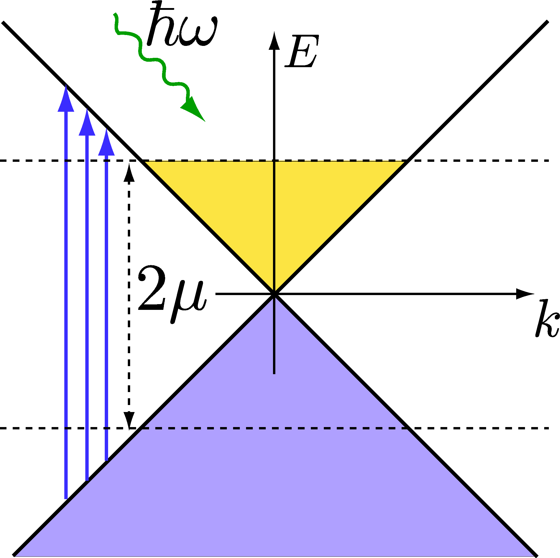
The non-null matrix elements in Eq.Β (14) contributing to the conductivity correspond to transitions between different bands conserving the momentum 𝐀𝐀\mathbf{k}. These transitions are said to be β€œvertical,” and, in addition, since they connect states in different bands, they are refereed to as being interband-like (see Fig.Β 2).

Refer to caption
Figure 2: Allowed interband transitions (vertical arrows) in graphene; a photon of energy ℏ​ωPlanck-constant-over-2-piπœ”\hbar\omega produces an excitation from the lower to the upper Dirac, as long as ℏ​ω>2​μPlanck-constant-over-2-piπœ”2πœ‡\hbar\omega>2\mu. The transitions conserve 𝐀𝐀\mathbf{k} and hence are said to be β€œvertical.” For ℏ​ω≀2​μ,Planck-constant-over-2-piπœ”2πœ‡\hbar\omega\leq 2\mu, Pauli blocking forbids any (interband) transition. In practice, due to disorder (impurities, etc.), the interband conductivity can be non-zero even for ℏ​ω≀2​μPlanck-constant-over-2-piπœ”2πœ‡\hbar\omega\leq 2\mu.

Taking the dipole approximation, A​(𝐫)β†’A0→𝐴𝐫subscript𝐴0A(\mathbf{r})\rightarrow A_{0}, the Hamiltonian [Eq.Β (8)] reads

H^^𝐻\displaystyle\hat{H} =\displaystyle= βˆ‘Ξ»,𝐀EΞ»(𝐀)c^Ξ»,𝐀†c^Ξ»,𝐀+evFA0(eβˆ’i​ω​t+c.c.)Γ—\displaystyle\sum_{\lambda,\mathbf{k}}E_{\lambda}(\mathbf{k})\hat{c}_{\lambda,\mathbf{k}}^{\dagger}\hat{c}_{\lambda,\mathbf{k}}+ev_{F}A_{0}\left(e^{-i\omega t}+\textrm{c.c.}\right)\times
Γ—βˆ‘π€jc,v,𝐀,𝐀xc^c,𝐀,σ†c^v,𝐀,Οƒ+(c⟷v).\displaystyle\times\sum_{\mathbf{k}}j_{c,v,\mathbf{k},\mathbf{k}}^{x}\hat{c}_{c,\mathbf{k},\sigma}^{\dagger}\hat{c}_{v,\mathbf{k},\sigma}+(c\longleftrightarrow v)\,. (16)

In the latter equation, Eλ​(𝐀)≑λ​ℏ​vF​ksubscriptπΈπœ†π€πœ†Planck-constant-over-2-pisubscriptπ‘£πΉπ‘˜E_{\lambda}(\mathbf{k})\equiv\lambda\hbar v_{F}k , and the subscripts c𝑐c (v𝑣v) denote electrons (holes).

As described above, we need to compute the time evolution of the operator P^v,c,𝐀​(t)=c^v,𝐀†​(t)​c^c,𝐀​(t)subscript^𝑃𝑣𝑐𝐀𝑑superscriptsubscript^𝑐𝑣𝐀†𝑑subscript^𝑐𝑐𝐀𝑑\hat{P}_{v,c,\mathbf{k}}(t)=\hat{c}_{v,\mathbf{k}}^{\dagger}(t)\hat{c}_{c,\mathbf{k}}(t). Straightforward algebra yields

dd​t​P^v,c,𝐀𝑑𝑑𝑑subscript^𝑃𝑣𝑐𝐀\displaystyle\frac{d}{dt}\hat{P}_{v,c,\mathbf{k}} =iℏ{[Ev(𝐀)βˆ’Ec(𝐀)]P^v,c,𝐀\displaystyle=\frac{i}{\hbar}\left\{\left[E_{v}(\mathbf{k})-E_{c}(\mathbf{k})\right]\hat{P}_{v,c,\mathbf{k}}\right.
+evFA0(eβˆ’i​ω​t+c.c.)jc,v,𝐀,𝐀x[n^c(t)βˆ’n^v(t)]},\displaystyle\left.+ev_{F}A_{0}\left(e^{-i\omega t}+\textrm{c.c.}\right)j_{c,v,\mathbf{k},\mathbf{k}}^{x}\left[\hat{n}_{c}(t)-\hat{n}_{v}(t)\right]\right\}\,, (17)

where we have defined the occupation operator for electrons (holes) as n^c​(v)​(t)≑c^c​(v),𝐀†​(t)​c^c​(v),𝐀​(t)subscript^𝑛𝑐𝑣𝑑superscriptsubscript^𝑐𝑐𝑣𝐀†𝑑subscript^𝑐𝑐𝑣𝐀𝑑\hat{n}_{c(v)}(t)\equiv\hat{c}_{c(v),\mathbf{k}}^{\dagger}(t)\hat{c}_{c(v),\mathbf{k}}(t). A similar equation holds for P^c,v,𝐀,Οƒsubscript^π‘ƒπ‘π‘£π€πœŽ\hat{P}_{c,v,\mathbf{k},\sigma} which can be obtained by interchanging c⟷vβŸ·π‘π‘£c\longleftrightarrow v.

To proceed, we take the average of Eq.Β (17) with respect to the unperturbed Hamiltonian, H0subscript𝐻0H_{0}, and approximate ⟨n^c​(t)βˆ’n^v​(t)⟩0β‰ƒβŸ¨n^cβˆ’n^v⟩0similar-to-or-equalssubscriptdelimited-⟨⟩subscript^𝑛𝑐𝑑subscript^𝑛𝑣𝑑0subscriptdelimited-⟨⟩subscript^𝑛𝑐subscript^𝑛𝑣0\langle\hat{n}_{c}(t)-\hat{n}_{v}(t)\rangle_{0}\simeq\langle\hat{n}_{c}-\hat{n}_{v}\rangle_{0}. Both procedures are consistent with an expansion of J^x​(t)subscript^𝐽π‘₯𝑑\hat{J}_{x}(t) up to first order in the parameter A0subscript𝐴0A_{0}. The solution of the above differential equation reads

⟨P^v,c,𝐀​(t)⟩0=P~v,c,𝐀​(Ο‰)​eβˆ’i​ω​t+P~v,c,𝐀​(βˆ’Ο‰)​ei​ω​t,subscriptdelimited-⟨⟩subscript^𝑃𝑣𝑐𝐀𝑑0subscript~π‘ƒπ‘£π‘π€πœ”superscriptπ‘’π‘–πœ”π‘‘subscript~π‘ƒπ‘£π‘π€πœ”superscriptπ‘’π‘–πœ”π‘‘\langle\hat{P}_{v,c,\mathbf{k}}(t)\rangle_{0}=\tilde{P}_{v,c,\mathbf{k}}(\omega)e^{-i\omega t}+\tilde{P}_{v,c,\mathbf{k}}(-\omega)e^{i\omega t}\,, (18)

with,

P~v,c,𝐀​(Ο‰)subscript~π‘ƒπ‘£π‘π€πœ”\displaystyle\tilde{P}_{v,c,\mathbf{k}}(\omega) =\displaystyle= e​vF​A0​jc,v,𝐀,𝐀xβ€‹βŸ¨n^c⟩0βˆ’βŸ¨n^v⟩0Ec​(𝐀)βˆ’Ev​(𝐀)βˆ’β„β€‹Ο‰βˆ’i​Γ,𝑒subscript𝑣𝐹subscript𝐴0superscriptsubscript𝑗𝑐𝑣𝐀𝐀π‘₯subscriptdelimited-⟨⟩subscript^𝑛𝑐0subscriptdelimited-⟨⟩subscript^𝑛𝑣0subscript𝐸𝑐𝐀subscript𝐸𝑣𝐀Planck-constant-over-2-piπœ”π‘–Ξ“\displaystyle ev_{F}A_{0}j_{c,v,\mathbf{k},\mathbf{k}}^{x}\frac{\langle\hat{n}_{c}\rangle_{0}-\langle\hat{n}_{v}\rangle_{0}}{E_{c}(\mathbf{k})-E_{v}(\mathbf{k})-\hbar\omega-i\Gamma}\,, (19)

and we have introduced an imaginary energy ΓΓ\Gamma by hand, so to account for disorder phenomenologically. The remaining term P~v,c,𝐀,σ​(Ο‰)subscript~π‘ƒπ‘£π‘π€πœŽπœ”\tilde{P}_{v,c,\mathbf{k},\sigma}(\omega) can be obtained from the latter expression by making Ο‰β†’βˆ’Ο‰β†’πœ”πœ”\omega\rightarrow-\omega and Ξ“β†’βˆ’Ξ“β†’Ξ“Ξ“\Gamma\rightarrow-\Gamma . From Eq.Β (15), the oscillator strength of the current density along the xπ‘₯x direction J~x​(Ο‰)subscript~𝐽π‘₯πœ”\tilde{J}_{x}(\omega) is seen to be given by

J~x​(Ο‰)=βˆ’e​vFAβ€‹βˆ‘π€[jv,c,𝐀,𝐀x​P~v,c,𝐀​(Ο‰)+jc,v,𝐀,𝐀x​P~c,v,𝐀​(Ο‰)].subscript~𝐽π‘₯πœ”π‘’subscript𝑣𝐹𝐴subscript𝐀delimited-[]superscriptsubscript𝑗𝑣𝑐𝐀𝐀π‘₯subscript~π‘ƒπ‘£π‘π€πœ”superscriptsubscript𝑗𝑐𝑣𝐀𝐀π‘₯subscript~π‘ƒπ‘π‘£π€πœ”\tilde{J}_{x}(\omega)=-\frac{ev_{F}}{A}\sum_{\mathbf{k}}[j_{v,c,\mathbf{k},\mathbf{k}}^{x}\tilde{P}_{v,c,\mathbf{k}}(\omega)+j_{c,v,\mathbf{k},\mathbf{k}}^{x}\tilde{P}_{c,v,\mathbf{k}}(\omega)]\,. (20)

The longitudinal optical conductivity, Οƒx​xsubscript𝜎π‘₯π‘₯\sigma_{xx}, follows from Eq.Β (7),

Οƒx​xinter​(Ο‰)=superscriptsubscript𝜎π‘₯π‘₯interπœ”absent\displaystyle\sigma_{xx}^{\textrm{inter}}(\omega)= gvgse2​vF2iβ€‹Ο‰βˆ«d2​𝐀4​π2(sin2θ𝐀)Γ—\displaystyle g_{v}g_{s}\frac{e^{2}v_{F}^{2}}{i\omega}\int\frac{d^{2}\mathbf{k}}{4\pi^{2}}\left(\sin^{2}\theta_{\mathbf{k}}\right)\times
Γ—nF​[Ev​(𝐀)]βˆ’nF​[Ec​(𝐀)]Ec​(𝐀)βˆ’Ev​(𝐀)βˆ’β„β€‹Ο‰βˆ’i​Γ+(c↔v).\displaystyle\times\frac{n_{F}\left[E_{v}(\mathbf{k})\right]-n_{F}\left[E_{c}(\mathbf{k})\right]}{E_{c}(\mathbf{k})-E_{v}(\mathbf{k})-\hbar\omega-i\Gamma}+(c\leftrightarrow v)\,. (21)

where nF​(E)=1/[e(Eβˆ’ΞΌ)/kB​T+1]subscript𝑛𝐹𝐸1delimited-[]superscriptπ‘’πΈπœ‡subscriptπ‘˜π΅π‘‡1n_{F}(E)=1/[e^{(E-\mu)/k_{B}T}+1] stands for the Fermi-Dirac distribution (ΞΌπœ‡\mu is the chemical potential). In deriving this expression, we have used the relation E~x​(Ο‰)=i​ω​A0subscript~𝐸π‘₯πœ”π‘–πœ”subscript𝐴0\tilde{E}_{x}(\omega)=i\omega A_{0}. Taking the clean limit Ξ“β†’0β†’Ξ“0\Gamma\rightarrow 0 and considering Ο‰>0πœ”0\omega>0 and T=0𝑇0T=0, one obtains the well- known result

Re​σx​xinter​(Ο‰)Resuperscriptsubscript𝜎π‘₯π‘₯interπœ”\displaystyle\textrm{Re}\,\,\sigma_{xx}^{\textrm{inter}}(\omega) =\displaystyle= π​e22​h​θ​(β„β€‹Ο‰βˆ’2​|ΞΌ|).πœ‹superscript𝑒22β„ŽπœƒPlanck-constant-over-2-piπœ”2πœ‡\displaystyle\frac{\pi e^{2}}{2h}\theta\left(\hbar\omega-2|\mu|\right)\,. (22)

The latter result is the Tβ†’0→𝑇0T\rightarrow 0 limit of Eq.Β (1). For photon energies higher than 2​μ2πœ‡2\mu (see Fig.Β 2), the interband conductivity is essentially frequency independent (up to energies of ∼similar-to\sim2 eV) and equals

Οƒg=π​e22​h,subscript𝜎gπœ‹superscript𝑒22β„Ž\sigma_{\textrm{g}}=\frac{\pi e^{2}}{2h}\,, (23)

which is nothing other than the universal conductivity of graphene mentioned in Sec.Β I. For ΞΌ=0πœ‡0\mu=0, and contrary to ordinary semiconductors, there is no frequency threshold for interband transitions: according to Eq.Β (22), some interband transitions will always be available for a sufficiently high photon frequency. As a consequence, Drude’s description will not suffice for a general description of the optical response of graphene.

In addition to the interband transitions discussed here, there is an intraband contribution in graphene which can be appreciable for ΞΌβ‰ 0πœ‡0\mu\neq 0. This contribution comes from nonvertical processes (e.g., via collisions with phonons), not included in the Hamiltonian Eq.Β (16). This contribution gives the Drude response and readsStauber

Re​σx​xintra​(Ο‰)=2​e2h​|ΞΌ|​Γℏ2​ω2+Ξ“2.Resuperscriptsubscript𝜎π‘₯π‘₯intraπœ”2superscript𝑒2β„Žπœ‡Ξ“superscriptPlanck-constant-over-2-pi2superscriptπœ”2superscriptΞ“2\textrm{Re}\,\sigma_{xx}^{\textrm{intra}}(\omega)=\frac{2e^{2}}{h}|\mu|\frac{\Gamma}{\hbar^{2}\omega^{2}+\Gamma^{2}}\,. (24)

Interestingly enough, the latter result can be derived from a full quantum mechanical calculation by considering a finite magnetic field intensity and taking the limit Bβ†’0→𝐡0B\rightarrow 0 in the end.Gusynin PRB 2006 This is because a magnetic field open gaps in the spectrum of a clean system, allowing for intraband transitions (see Sec.Β II.4). A semiclassical calculation also leads to an equivalent result (Sec.Β II.5).

II.4 Optical conductivity of graphene in a magnetic field

In what follows, we show that the EOM method can be employed to study the magneto-optical response of graphene along the same lines as in Sec.Β II.3. The presence of a transverse magnetic field in the Hamiltonian develops LLs, and hence we must start from the eigenstates given in Eq.Β (6). The latter defines the field operator, Ψ​(𝐫,t)=βˆ‘n,kyc^n,ky​(t)β€‹Οˆn,ky​(𝐫)Ψ𝐫𝑑subscript𝑛subscriptπ‘˜π‘¦subscript^𝑐𝑛subscriptπ‘˜π‘¦π‘‘subscriptπœ“π‘›subscriptπ‘˜π‘¦π«\Psi(\mathbf{r},t)=\sum_{n,k_{y}}\hat{c}_{n,k_{y}}(t)\psi_{n,k_{y}}(\mathbf{r}) (together with the respective Hermitian conjugate); the index n𝑛n labels the degenerate LL with energy given by Eq. (5). The field operator can be written as

Ψ​(𝐫,t)Ψ𝐫𝑑\displaystyle\Psi(\mathbf{r},t) =\displaystyle= 12​Lβ€‹βˆ‘nβ‰ 0,ky(Ο•|n|βˆ’1​(x)i​sign​(n)​ϕ|n|​(x))​ei​ky​y​c^n,ky12𝐿subscript𝑛0subscriptπ‘˜π‘¦subscriptitalic-ϕ𝑛1π‘₯𝑖sign𝑛subscriptitalic-ϕ𝑛π‘₯superscript𝑒𝑖subscriptπ‘˜π‘¦π‘¦subscript^𝑐𝑛subscriptπ‘˜π‘¦\displaystyle\frac{1}{\sqrt{2L}}\sum_{n\neq 0,k_{y}}\left(\begin{array}[]{c}\phi_{|n|-1}(x)\\ i\textrm{sign}(n)\phi_{|n|}(x)\end{array}\right)e^{ik_{y}y}\hat{c}_{n,k_{y}} (30)
+1Lβ€‹βˆ‘ky(0Ο•0​(x))​ei​ky​y​c^0,ky.1𝐿subscriptsubscriptπ‘˜π‘¦0subscriptitalic-Ο•0π‘₯superscript𝑒𝑖subscriptπ‘˜π‘¦π‘¦subscript^𝑐0subscriptπ‘˜π‘¦\displaystyle+\frac{1}{\sqrt{L}}\sum_{k_{y}}\left(\begin{array}[]{c}0\\ \phi_{0}(x)\end{array}\right)e^{ik_{y}y}\hat{c}_{0,k_{y}}\,.

This peculiar spinorial structure, with a single level being highlighted, is on the basis of non-standard features in the magneto-optical conductivity of graphene.AnamQHE_Sharapov05 ; Peres 2006 ; Carbotte2006_MWresponse ; Carbotte2007

II.4.1 The longitudinal conductivity

According to Eq.Β (7), the calculation of the longitudinal conductivity requires computation of the average value of the current density operator along the xπ‘₯x direction,

Jx​(t)=βˆ‘n,nβ€²βˆ‘ky,kyβ€²βŸ¨n,ky|jx|nβ€²,kyβ€²βŸ©β€‹βŸ¨c^n,ky†​(t)​c^nβ€²,ky′​(t)⟩.subscript𝐽π‘₯𝑑subscript𝑛superscript𝑛′subscriptsubscriptπ‘˜π‘¦superscriptsubscriptπ‘˜π‘¦β€²quantum-operator-product𝑛subscriptπ‘˜π‘¦subscript𝑗π‘₯superscript𝑛′superscriptsubscriptπ‘˜π‘¦β€²delimited-⟨⟩superscriptsubscript^𝑐𝑛subscriptπ‘˜π‘¦β€ π‘‘subscript^𝑐superscript𝑛′superscriptsubscriptπ‘˜π‘¦β€²π‘‘J_{x}(t)=\sum_{n,n^{\prime}}\sum_{k_{y},k_{y}^{\prime}}\langle n,k_{y}|j_{x}|n^{\prime},k_{y}^{\prime}\rangle\langle\hat{c}_{n,k_{y}}^{\dagger}(t)\hat{c}_{n^{\prime},k_{y}^{\prime}}(t)\rangle\,. (31)

Using the LL wavefunctions [Eq.Β (6)], we easily find the non-zero matrix elements to be,

⟨0,ky|jx|Β±1,kyβ€²βŸ©=quantum-operator-product0subscriptπ‘˜π‘¦subscript𝑗π‘₯plus-or-minus1superscriptsubscriptπ‘˜π‘¦β€²absent\displaystyle\langle 0,k_{y}|j_{x}|\pm 1,k_{y}^{\prime}\rangle= βˆ’e​vF2​A​δky,kyβ€²,𝑒subscript𝑣𝐹2𝐴subscript𝛿subscriptπ‘˜π‘¦superscriptsubscriptπ‘˜π‘¦β€²\displaystyle-\frac{ev_{F}}{\sqrt{2}A}\delta_{k_{y},k_{y}^{\prime}}\,, (32)
⟨n,ky|jx|nβ€²,kyβ€²βŸ©=quantum-operator-product𝑛subscriptπ‘˜π‘¦subscript𝑗π‘₯superscript𝑛′superscriptsubscriptπ‘˜π‘¦β€²absent\displaystyle\langle n,k_{y}|j_{x}|n^{\prime},k_{y}^{\prime}\rangle= βˆ’e​vF2​Ai[sign(nβ€²)Ξ΄|n|βˆ’1,|nβ€²|\displaystyle-\frac{ev_{F}}{2A}i\left[\textrm{sign}(n^{\prime})\delta_{|n|-1,|n^{\prime}|}\right.
βˆ’sign(n)Ξ΄|n|,|nβ€²|βˆ’1]Ξ΄ky,kyβ€²,\displaystyle\left.-\textrm{sign}(n)\delta_{|n|,|n^{\prime}|-1}\right]\delta_{k_{y},k_{y}^{\prime}}\,, (33)

where in the last line n,nβ€²β‰ 0𝑛superscript𝑛′0n,n^{\prime}\neq 0. These statements show that the optical transitions conserve kysubscriptπ‘˜π‘¦k_{y} and occur between levels with indexes n𝑛n and nβ€²superscript𝑛′n^{\prime} satisfying |n|βˆ’|nβ€²|=Β±1𝑛superscript𝑛′plus-or-minus1|n|-|n^{\prime}|=\pm 1.

Two sets of transitions are thus allowed: intraband transitions, occurring within the same band, and, as in the absence of a magnetic field, transitions connecting LLs in the valence and conduction bands, which are interband-like. Transitions involving the zero-energy state n=0𝑛0n=0 can be considered either intraband- or interband-like, since the zero-energy state is shared between electrons and holes. For the sake of simplicity in defining the set of EOMs, throughout, we classify transitions involving the zero-energy state as being interband.

In order to clearly distinguish among the possible types of transitions, we define

c^n,ky≑{cnfor ​n>0v|n|for ​n<0a0for ​n=0,subscript^𝑐𝑛subscriptπ‘˜π‘¦casessubscript𝑐𝑛for 𝑛0subscript𝑣𝑛for 𝑛0subscriptπ‘Ž0for 𝑛0\hat{c}_{n,k_{y}}\equiv\begin{cases}c_{n}&\,\textrm{for }n>0\\ v_{|n|}&\,\textrm{for }n<0\\ a_{0}&\,\textrm{for }n=0\end{cases}\,, (34)

with the Hermitian conjugates following identical redefinitions. Note that with these definitions the subscript n𝑛n in the operators take only positive integer values.

a. Interband transitionsβ€”Using the field operator in the presence of a magnetic field [Eq.Β (30)], and keeping track of just the interband terms for the moment, the full Hamiltonian takes the form

H^=^𝐻absent\displaystyle\hat{H}= βˆ‘nβ‰₯1[En​cn†​cn+Eβˆ’n​vn†​vn]subscript𝑛1delimited-[]subscript𝐸𝑛superscriptsubscript𝑐𝑛†subscript𝑐𝑛subscript𝐸𝑛superscriptsubscript𝑣𝑛†subscript𝑣𝑛\displaystyle\sum_{n\geq 1}\left[E_{n}c_{n}^{\dagger}c_{n}+E_{-n}v_{n}^{\dagger}v_{n}\right]
+\displaystyle+ e​vF​A​(t)2​[c1†​a0+v1†​a0+h.c.]𝑒subscript𝑣𝐹𝐴𝑑2delimited-[]superscriptsubscript𝑐1†subscriptπ‘Ž0superscriptsubscript𝑣1†subscriptπ‘Ž0h.c.\displaystyle\frac{ev_{F}A(t)}{\sqrt{2}}\left[c_{1}^{\dagger}a_{0}+v_{1}^{\dagger}a_{0}+\textrm{h.c.}\right]
βˆ’\displaystyle- e​vF​A​(t)2​iβ€‹βˆ‘nβ‰₯1[P^n(1)+P^n(2)βˆ’h.c.],𝑒subscript𝑣𝐹𝐴𝑑2𝑖subscript𝑛1delimited-[]superscriptsubscript^𝑃𝑛1superscriptsubscript^𝑃𝑛2h.c.\displaystyle\frac{ev_{F}A(t)}{2}i\sum_{n\geq 1}\left[\hat{P}_{n}^{(1)}+\hat{P}_{n}^{(2)}-\textrm{h.c.}\right]\,, (35)

where A​(t)≑A0​(eβˆ’i​ω​t+c.c.)𝐴𝑑subscript𝐴0superscriptπ‘’π‘–πœ”π‘‘c.c.A(t)\equiv A_{0}(e^{-i\omega t}+\textrm{c.c.}), and

P^n(1)superscriptsubscript^𝑃𝑛1\displaystyle\hat{P}_{n}^{(1)} =cn†​vn+1,absentsuperscriptsubscript𝑐𝑛†subscript𝑣𝑛1\displaystyle=c_{n}^{\dagger}v_{n+1}\,, (36)
P^n(2)superscriptsubscript^𝑃𝑛2\displaystyle\hat{P}_{n}^{(2)} =cn+1†​vn.absentsuperscriptsubscript𝑐𝑛1†subscript𝑣𝑛\displaystyle=c_{n+1}^{\dagger}v_{n}\,. (37)

(Also, for clarity, we have omitted kysubscriptπ‘˜π‘¦k_{y} under all the summation signs.) The first line in Eq.Β (35) describes massless Dirac fermions in a transverse magnetic field and the remaining lines contain the electronic transitions among different LLs induced by the external electric field.

The interband current density along the xπ‘₯x direction can be recast into the form

J^x​(t)subscript^𝐽π‘₯𝑑\displaystyle\hat{J}_{x}(t) =βˆ’12​A​e​vF​(c1†​a0+v1†​a0+h.c.)absent12𝐴𝑒subscript𝑣𝐹superscriptsubscript𝑐1†subscriptπ‘Ž0superscriptsubscript𝑣1†subscriptπ‘Ž0h.c.\displaystyle=-\frac{1}{\sqrt{2}A}ev_{F}\left(c_{1}^{\dagger}a_{0}+v_{1}^{\dagger}a_{0}+\textrm{h.c.}\right)
+12​A​e​vFβ€‹βˆ‘nβ‰₯1(i​P^n(1)+i​P^n(2)+h.c.).12𝐴𝑒subscript𝑣𝐹subscript𝑛1𝑖superscriptsubscript^𝑃𝑛1𝑖superscriptsubscript^𝑃𝑛2h.c.\displaystyle+\frac{1}{2A}ev_{F}\sum_{n\geq 1}\left(i\hat{P}_{n}^{(1)}+i\hat{P}_{n}^{(2)}+\textrm{h.c.}\right)\,. (38)

From the form of the current we see that there are two basic sets of EOMs to be solved: the first set refers to the time evolution of operators involving the zero-energy state (c1†​a0superscriptsubscript𝑐1†subscriptπ‘Ž0c_{1}^{\dagger}a_{0}, v1†​a0superscriptsubscript𝑣1†subscriptπ‘Ž0v_{1}^{\dagger}a_{0}, and Hermitian conjugates), while the other set refers to higher energy LLs. Take, for instance, the operator P^n(1)superscriptsubscript^𝑃𝑛1\hat{P}_{n}^{(1)} belonging to the latter set; as in the case of zero magnetic field (Sec.Β II.3), the commutator [H,P^n(1)]𝐻superscriptsubscript^𝑃𝑛1[H,\hat{P}_{n}^{(1)}] gives rise to (i) occupation number operators (vn+1†​vn+1superscriptsubscript𝑣𝑛1†subscript𝑣𝑛1v_{n+1}^{\dagger}v_{n+1} and cn†​cnsuperscriptsubscript𝑐𝑛†subscript𝑐𝑛c_{n}^{\dagger}c_{n}), and (ii) a free evolution term, that is, the operator P^n(1)superscriptsubscript^𝑃𝑛1\hat{P}_{n}^{(1)} itself. In addition, intraband terms with |n|βˆ’|nβ€²|=Β±2𝑛superscript𝑛′plus-or-minus2|n|-|n^{\prime}|=\pm 2 show up, namely, cn†​cn+2superscriptsubscript𝑐𝑛†subscript𝑐𝑛2c_{n}^{\dagger}c_{n+2}, vnβˆ’1†​vn+1superscriptsubscript𝑣𝑛1†subscript𝑣𝑛1v_{n-1}^{\dagger}v_{n+1} and a0†​v2​δn,1superscriptsubscriptπ‘Ž0†subscript𝑣2subscript𝛿𝑛1a_{0}^{\dagger}v_{2}\delta_{n,1}. These terms do not originate real intraband transitions, since the respective current density matrix elements are null.

We are now in the position to write the prototype EOMs governing the interaction of Landau quasiparticles with an external oscillating electric field,

ℏi​dd​t​P^n(1)Planck-constant-over-2-pi𝑖𝑑𝑑𝑑superscriptsubscript^𝑃𝑛1\displaystyle\frac{\hbar}{i}\frac{d}{dt}\hat{P}_{n}^{(1)} =[Enβˆ’Eβˆ’(n+1)]P^n(1)βˆ’i2evFA(t)Γ—\displaystyle=\left[E_{n}-E_{-(n+1)}\right]\hat{P}_{n}^{(1)}-\frac{i}{2}ev_{F}A(t)\times
Γ—[vn+1†​vn+1βˆ’cn†​cn],absentdelimited-[]superscriptsubscript𝑣𝑛1†subscript𝑣𝑛1superscriptsubscript𝑐𝑛†subscript𝑐𝑛\displaystyle\times[v_{n+1}^{\dagger}v_{n+1}-c_{n}^{\dagger}c_{n}]\,, (39)
ℏi​dd​t​P^cPlanck-constant-over-2-pi𝑖𝑑𝑑𝑑subscript^𝑃𝑐\displaystyle\frac{\hbar}{i}\frac{d}{dt}\hat{P}_{c} =E1​P^c+12​e​vF​A​(t)​[a0†​a0βˆ’c1†​c1],absentsubscript𝐸1subscript^𝑃𝑐12𝑒subscript𝑣𝐹𝐴𝑑delimited-[]superscriptsubscriptπ‘Ž0†subscriptπ‘Ž0superscriptsubscript𝑐1†subscript𝑐1\displaystyle=E_{1}\hat{P}_{c}+\frac{1}{\sqrt{2}}ev_{F}A(t)[a_{0}^{\dagger}a_{0}-c_{1}^{\dagger}c_{1}]\,, (40)

where we have omitted the time dependence of the operators and defined P^c​(v)=c​(v)​a01†subscript^𝑃𝑐𝑣𝑐𝑣subscriptsuperscriptsubscriptπ‘Ž0†1\hat{P}_{c(v)}=c(v){}_{1}^{\dagger}a_{0}. The remaining operators obey similar equations. [The EOM for P^n(2)superscriptsubscript^𝑃𝑛2\hat{P}_{n}^{(2)} is obtained making P^n(1)β†’P^n(2)β†’superscriptsubscript^𝑃𝑛1superscriptsubscript^𝑃𝑛2\hat{P}_{n}^{(1)}\rightarrow\hat{P}_{n}^{(2)}and interchanging n𝑛n with n+1𝑛1n+1 on the right-hand side of Eq.Β (39). As for P^vsubscript^𝑃𝑣\hat{P}_{v}, we let P^cβ†’P^vβ†’subscript^𝑃𝑐subscript^𝑃𝑣\hat{P}_{c}\rightarrow\hat{P}_{v}, E1β†’Eβˆ’1β†’subscript𝐸1subscript𝐸1E_{1}\rightarrow E_{-1}, and c1​(c1†)β†’v1​(v1†)β†’subscript𝑐1superscriptsubscript𝑐1†subscript𝑣1superscriptsubscript𝑣1†c_{1}(c_{1}^{\dagger})\rightarrow v_{1}(v_{1}^{\dagger}) in Eq.Β (40).]

Refer to caption
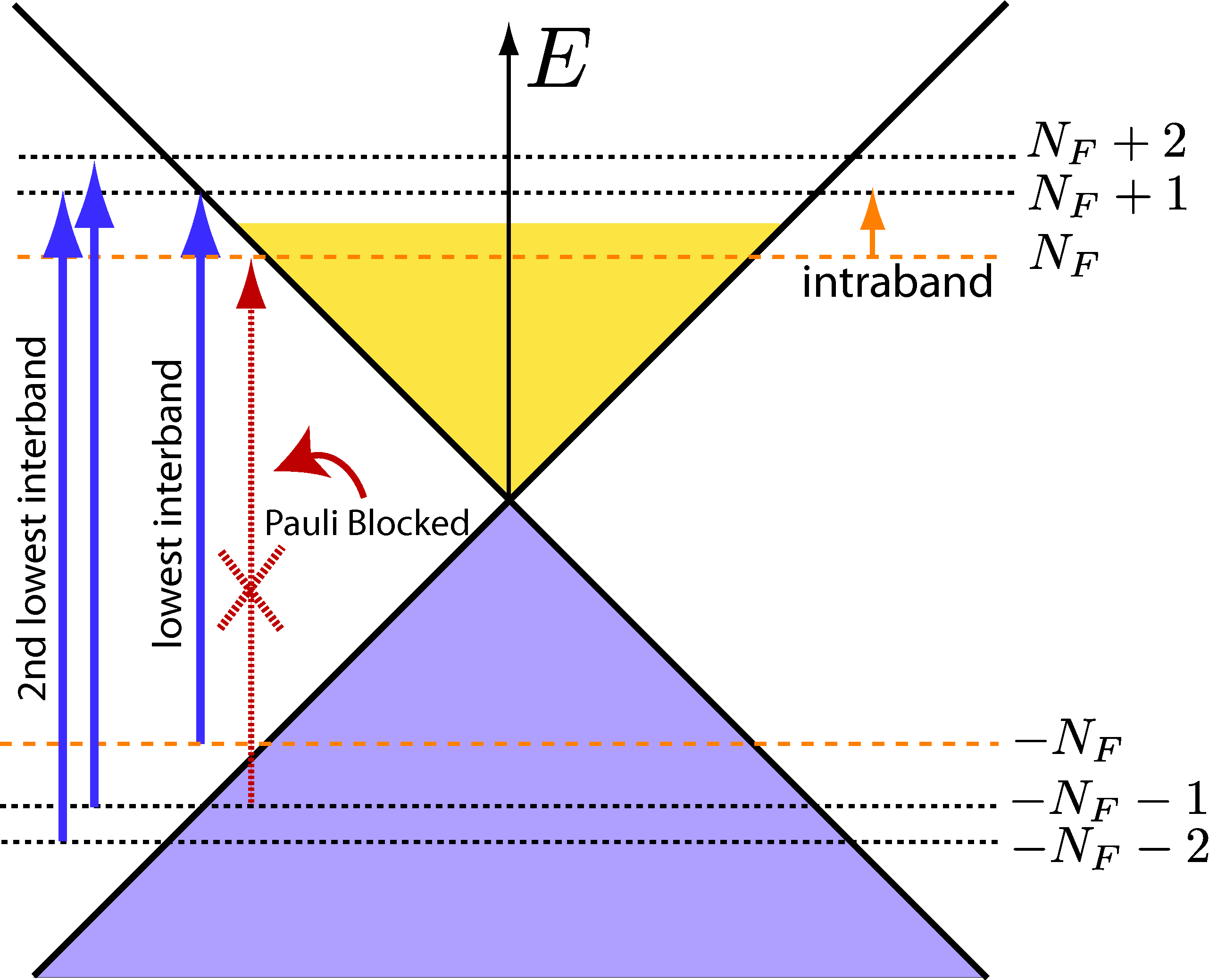
Figure 3: Schematic of electronic transitions contributing to Οƒx​x​(Ο‰)subscript𝜎π‘₯π‘₯πœ”\sigma_{xx}(\omega) of doped graphene in a magnetic field. In this example, EFβ‰₯E1subscript𝐸𝐹subscript𝐸1E_{F}\geq E_{1}, and thus the last occupied LL, n=NFβ‰₯1𝑛subscript𝑁𝐹1n=N_{F}\geq 1, belongs to the conduction band. Two types of transitions take place: (i) interband transitions, connecting LLs from the lower cone (valence band) with LLs in the upper cone (conduction band), and (ii) intraband transitions within the upper cone. Intraband transitions are limited to adjacent LLs: NFβ†’NF+1β†’subscript𝑁𝐹subscript𝑁𝐹1N_{F}\rightarrow N_{F}+1. The figure shows the following interband transitions: (a) the pair βˆ’NFβ†’NF+1β†’subscript𝑁𝐹subscript𝑁𝐹1-N_{F}\rightarrow N_{F}+1 and βˆ’NFβˆ’1β†’NFβ†’subscript𝑁𝐹1subscript𝑁𝐹-N_{F}-1\rightarrow N_{F}, whose energy difference is EN+1+ENsubscript𝐸𝑁1subscript𝐸𝑁E_{N+1}+E_{N} (the lowest interband energy; note that transitions βˆ’NFβˆ’1β†’NFβ†’subscript𝑁𝐹1subscript𝑁𝐹-N_{F}-1\rightarrow N_{F} are forbidden because n=NF𝑛subscript𝑁𝐹n=N_{F} is occupied); and (b) the pair βˆ’NFβˆ’1β†’NF+2β†’subscript𝑁𝐹1subscript𝑁𝐹2-N_{F}-1\rightarrow N_{F}+2 and βˆ’NFβˆ’2β†’NF+1β†’subscript𝑁𝐹2subscript𝑁𝐹1-N_{F}-2\rightarrow N_{F}+1. The respective energy difference is EN+1+EN+2subscript𝐸𝑁1subscript𝐸𝑁2E_{N+1}+E_{N+2} (the second lowest interband energy difference), and in this case both transitions take place. Transitions with higher energy differences are not represented.

To solve the above set of differential equations to first order in A0subscript𝐴0A_{0}, we proceed as in Sec.Β II.3. Taking the average value βŸ¨β€¦βŸ©0subscriptdelimited-βŸ¨βŸ©β€¦0\langle...\rangle_{0} of each EOM with respect to the unperturbed Hamiltonian, H0subscript𝐻0H_{0}, the solution for each operator O𝑂O can be written as ⟨O​(t)⟩0=O~​(Ο‰)​eβˆ’i​ω​t+O~​(βˆ’Ο‰)​ei​ω​tsubscriptdelimited-βŸ¨βŸ©π‘‚π‘‘0~π‘‚πœ”superscriptπ‘’π‘–πœ”π‘‘~π‘‚πœ”superscriptπ‘’π‘–πœ”π‘‘\langle O(t)\rangle_{0}=\tilde{O}(\omega)e^{-i\omega t}+\tilde{O}(-\omega)e^{i\omega t}, where the oscillator strengths read

P~n(1)​(Ο‰)superscriptsubscript~𝑃𝑛1πœ”\displaystyle\tilde{P}_{n}^{(1)}(\omega) =βˆ’i2​e​vF​A0β€‹βŸ¨vn+1†​vn+1⟩0βˆ’βŸ¨cn†​cn⟩0Eβˆ’(n+1)βˆ’Enβˆ’β„β€‹Ο‰βˆ’i​Γ,absent𝑖2𝑒subscript𝑣𝐹subscript𝐴0subscriptdelimited-⟨⟩superscriptsubscript𝑣𝑛1†subscript𝑣𝑛10subscriptdelimited-⟨⟩superscriptsubscript𝑐𝑛†subscript𝑐𝑛0subscript𝐸𝑛1subscript𝐸𝑛Planck-constant-over-2-piπœ”π‘–Ξ“\displaystyle=-\frac{i}{2}ev_{F}A_{0}\frac{\langle v_{n+1}^{\dagger}v_{n+1}\rangle_{0}-\langle c_{n}^{\dagger}c_{n}\rangle_{0}}{E_{-(n+1)}-E_{n}-\hbar\omega-i\Gamma}\,, (41)
P~c​(Ο‰)subscript~π‘ƒπ‘πœ”\displaystyle\tilde{P}_{c}(\omega) =12​e​vF​A0β€‹βŸ¨a0†​a0⟩0βˆ’βŸ¨c1†​c1⟩0βˆ’E1βˆ’β„β€‹Ο‰βˆ’i​Γ,absent12𝑒subscript𝑣𝐹subscript𝐴0subscriptdelimited-⟨⟩superscriptsubscriptπ‘Ž0†subscriptπ‘Ž00subscriptdelimited-⟨⟩superscriptsubscript𝑐1†subscript𝑐10subscript𝐸1Planck-constant-over-2-piπœ”π‘–Ξ“\displaystyle=\frac{1}{\sqrt{2}}ev_{F}A_{0}\frac{\langle a_{0}^{\dagger}a_{0}\rangle_{0}-\langle c_{1}^{\dagger}c_{1}\rangle_{0}}{-E_{1}-\hbar\omega-i\Gamma}\,, (42)

and where, as in Sec.Β II.3, we have added a imaginary energy ΓΓ\Gamma to account for level broadening. The solutions for P~n(2)​(Ο‰)superscriptsubscript~𝑃𝑛2πœ”\tilde{P}_{n}^{(2)}(\omega) and P~v​(Ο‰)subscript~π‘ƒπ‘£πœ”\tilde{P}_{v}(\omega) can be obtained from the latter expressions as described below Eq.Β (40).

Combining these results and Eq.Β (38), we easily find

J~x​(Ο‰)subscript~𝐽π‘₯πœ”\displaystyle\tilde{J}_{x}(\omega) =\displaystyle= 12​AevFβˆ‘ky{βˆ‘nβ‰₯1[iP~n1(Ο‰)+iP~n2(Ο‰)]\displaystyle\frac{1}{2A}ev_{F}\sum_{k_{y}}\left\{\sum_{n\geq 1}\left[i\tilde{P}_{n}^{1}(\omega)+i\tilde{P}_{n}^{2}(\omega)\right]\right. (43)
βˆ’2[P~c(Ο‰)+P~v(Ο‰)]+"c.c. term"},\displaystyle\left.-\sqrt{2}\left[\tilde{P}_{c}(\omega)+\tilde{P}_{v}(\omega)\right]+"\textrm{c.c. term}"\right\}\,,

where the summation over kysubscriptπ‘˜π‘¦k_{y} has been restored. This summation yields the degeneracy of the LLs βˆ‘ky=A/(2​π​lB2)subscriptsubscriptπ‘˜π‘¦π΄2πœ‹superscriptsubscript𝑙𝐡2\sum_{k_{y}}=A/(2\pi l_{B}^{2}). The last term in the above equation (i.e., the c.c. term) is obtained taking the complex conjugate and making Ο‰β†’βˆ’Ο‰β†’πœ”πœ”\omega\rightarrow-\omega of all the previous terms.

The final expression for the longitudinal (interband) conductivity is derived in two steps: (i) dividing the Eq.Β (43) by E~x​(Ο‰)subscript~𝐸π‘₯πœ”\tilde{E}_{x}(\omega) [Eq.Β (7)], and (ii) undertaking appropriate regularization to remove the divergent factor 1/Ο‰1πœ”1/\omega,

Οƒx​xinter​(Ο‰)superscriptsubscript𝜎π‘₯π‘₯interπœ”\displaystyle\sigma_{xx}^{\textrm{inter}}(\omega) =e2​vF2​ℏ2​π​lB2​iβ€‹βˆ‘n=0Nc(1+Ξ΄n,0)β€‹βˆ‘Ξ±=Β±1Ξ±absentsuperscript𝑒2superscriptsubscript𝑣𝐹2Planck-constant-over-2-pi2πœ‹superscriptsubscript𝑙𝐡2𝑖superscriptsubscript𝑛0subscript𝑁c1subscript𝛿𝑛0subscript𝛼plus-or-minus1𝛼\displaystyle=\frac{e^{2}v_{F}^{2}\hbar}{2\pi l_{B}^{2}}i\sum_{n=0}^{N_{\textrm{c}}}(1+\delta_{n,0})\sum_{\alpha=\pm 1}\alpha
Γ—[1Eβˆ’(n+1)βˆ’EnΓ—nF​[Eβˆ’(n+1)]βˆ’nF​[En]Eβˆ’(n+1)βˆ’Enβˆ’Ξ±β€‹(ℏ​ω+i​Γ)\displaystyle\times\left[\frac{1}{E_{-(n+1)}-E_{n}}\times\frac{n_{F}[E_{-(n+1)}]-n_{F}[E_{n}]}{E_{-(n+1)}-E_{n}-\alpha(\hbar\omega+i\Gamma)}\right.
+(n↔n+1)].\displaystyle\left.+(n\leftrightarrow n+1)\right]\,. (44)

The above expression is analytic in the upper-half plane and finite at Ο‰=0πœ”0\omega=0, thus obeying Kramers-Kronig causality relations. (We refer to AppendixΒ C for the derivation and physical grounds of the regularization procedure.) Note that, as usual when dealing with low-energy theories, a cutoff energy Ecutsubscript𝐸cutE_{\textrm{cut}} of the order of the bandwidth must be considered for consistency; we take n≀Nc𝑛subscript𝑁cn\leq N_{\mathrm{c}}, with Nc=int​[(Ecut/E1)2]subscript𝑁cintdelimited-[]superscriptsubscript𝐸cutsubscript𝐸12N_{\textrm{c}}=\textrm{int}[(E_{\textrm{cut}}/E_{1})^{2}], where int​[…]intdelimited-[]…\textrm{int}[...] denotes the integer part. Ncsubscript𝑁cN_{\textrm{c}} varies roughly as 104​Bβˆ’1superscript104superscript𝐡110^{4}B^{-1} with B𝐡B in teslas. Within the physical relevant range for Ecutsubscript𝐸cutE_{\textrm{cut}}, these summations converge quite rapidly; the figures in the present work have Ecutβ‰ˆt≃subscript𝐸cut𝑑similar-to-or-equalsabsentE_{\textrm{cut}}\approx t\simeq2.7Β eV.

b. Intraband transitionsβ€”The intraband interaction Hamiltonian reads

H^intintra=i2​e​vF​A​(t)β€‹βˆ‘nβ‰₯1[vn†​vn+1βˆ’cn†​cn+1βˆ’h.c.],superscriptsubscript^𝐻intintra𝑖2𝑒subscript𝑣𝐹𝐴𝑑subscript𝑛1delimited-[]superscriptsubscript𝑣𝑛†subscript𝑣𝑛1superscriptsubscript𝑐𝑛†subscript𝑐𝑛1h.c.\hat{H}_{\textrm{int}}^{\textrm{intra}}=\frac{i}{2}ev_{F}A(t)\sum_{n\geq 1}\left[v_{n}^{\dagger}v_{n+1}-c_{n}^{\dagger}c_{n+1}-\textrm{h.c.}\right]\,, (45)

and the zero-energy operators (a0subscriptπ‘Ž0a_{0} and a0†superscriptsubscriptπ‘Ž0†a_{0}^{\dagger}) are absent given our classification of intraband transitions [see Eq.Β (34) and the following text]. The calculation follows identical steps to the interband conductivity and, hence, is not repeated. The final expression for the (regular) intraband diagonal conductivity reads,

Οƒx​xintra​(Ο‰)superscriptsubscript𝜎π‘₯π‘₯intraπœ”\displaystyle\sigma_{xx}^{\textrm{intra}}(\omega) =e2​vF2​ℏ2​π​lB2iβˆ‘Ξ±=Β±1Ξ±βˆ‘n=1Nc[1En+1βˆ’EnΓ—\displaystyle=\frac{e^{2}v_{F}^{2}\hbar}{2\pi l_{B}^{2}}i\sum_{\alpha=\pm 1}\alpha\sum_{n=1}^{N_{c}}\left[\frac{1}{E_{n+1}-E_{n}}\times\right.
Γ—nF​[En+1]βˆ’nF​[En]En+1βˆ’Enβˆ’Ξ±β€‹(ℏ​ω+i​Γ)absentsubscript𝑛𝐹delimited-[]subscript𝐸𝑛1subscript𝑛𝐹delimited-[]subscript𝐸𝑛subscript𝐸𝑛1subscript𝐸𝑛𝛼Planck-constant-over-2-piπœ”π‘–Ξ“\displaystyle\times\frac{n_{F}[E_{n+1}]-n_{F}[E_{n}]}{E_{n+1}-E_{n}-\alpha\left(\hbar\omega+i\Gamma\right)}
+(Enβ†’βˆ’En∧En+1β†’βˆ’En+1)].\displaystyle\left.+(E_{n}\rightarrow-E_{n}\wedge E_{n+1}\rightarrow-E_{n+1})\right]\,. (46)

The full longitudinal conductivity Οƒx​x​(Ο‰)subscript𝜎π‘₯π‘₯πœ”\sigma_{xx}(\omega) is given by adding its interband and intraband counterparts, that is, Eqs.Β (44) and (46), respectively; straightforward algebra yields

Οƒx​x​(Ο‰)=e2hβ€‹βˆ‘nβ‰ m=βˆ’NcNcΞ›n​mx​xi​En​m​nF​(En)βˆ’nF​(Em)ℏ​ω+En​m+i​Γ,subscript𝜎π‘₯π‘₯πœ”superscript𝑒2β„Žsuperscriptsubscriptπ‘›π‘šsubscript𝑁𝑐subscript𝑁𝑐superscriptsubscriptΞ›π‘›π‘šπ‘₯π‘₯𝑖subscriptπΈπ‘›π‘šsubscript𝑛𝐹subscript𝐸𝑛subscript𝑛𝐹subscriptπΈπ‘šPlanck-constant-over-2-piπœ”subscriptπΈπ‘›π‘šπ‘–Ξ“\sigma_{xx}(\omega)=\frac{e^{2}}{h}\sum_{n\neq m=-N_{c}}^{N_{c}}\frac{\Lambda_{nm}^{xx}}{iE_{nm}}\frac{n_{F}(E_{n})-n_{F}(E_{m})}{\hbar\omega+E_{nm}+i\Gamma}\,, (47)

with En​m=Enβˆ’EmsubscriptπΈπ‘›π‘šsubscript𝐸𝑛subscriptπΈπ‘šE_{nm}=E_{n}-E_{m}, and where we have defined the longitudinal matrix elements

Ξ›n​mx​x=ℏ2​vF2lB2​(1+Ξ΄m,0+Ξ΄n,0)​δ|m|βˆ’|n|,Β±1.superscriptsubscriptΞ›π‘›π‘šπ‘₯π‘₯superscriptPlanck-constant-over-2-pi2superscriptsubscript𝑣𝐹2superscriptsubscript𝑙𝐡21subscriptπ›Ώπ‘š0subscript𝛿𝑛0subscriptπ›Ώπ‘šπ‘›plus-or-minus1\Lambda_{nm}^{xx}=\frac{\hbar^{2}v_{F}^{2}}{l_{B}^{2}}(1+\delta_{m,0}+\delta_{n,0})\delta_{|m|-|n|,\pm 1}\,. (48)

EquationΒ (47) is the main result of the present section. It coincides with Eq.Β (7) in Ref.Β CarbotteIJMP2007, obtained via a Green’s function calculation in the bubble approximation and, also, with a Kubo formula calculation within the Dirac cone approximation (see AppendixΒ C). We note in passing that, on top of the interband and intraband contributions discussed here, there is a correction arising from phonon-electron coupling. At low temperatures and zero field, this correction is expected to be small.Stauber At a high magnetic field, though, a recent calculation shows that phonon energy peaks split the LLs nearby,Carbotte_Phonons which can lead to a measurable signature in magneto-optical experiments.

II.4.2 The general properties of Οƒx​x​(Ο‰)subscript𝜎π‘₯π‘₯πœ”\sigma_{xx}(\omega)

In what follows, we overview the main features of graphene’s longitudinal magneto-optical conductivity, an essential step to understanding the Faraday rotation in graphene (Sec.Β III).

Refer to caption
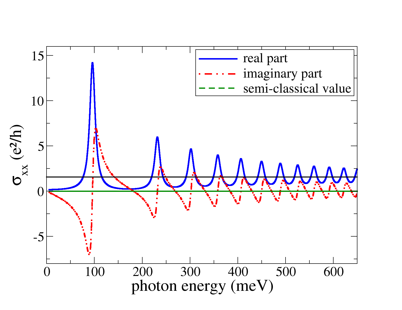
Figure 4: Longitudinal magneto-optical conductivity as a function of the photon energy for a field of 777Β T, zero chemical potential, T=17𝑇17T=17Β K, and Ξ“=6.8Ξ“6.8\Gamma=6.8Β meV (∼79similar-toabsent79\sim 79Β K). The horizontal dashed-dot (black) line marks the graphene’s universal ac-conductivity background [Eq.Β (1)].

a. Low electronic densityβ€”At a low electronic density, more precisely, for |EF|<E1subscript𝐸𝐹subscript𝐸1|E_{F}|<E_{1}, no intraband transitions can take place. Because the LL energy scale in graphene is relatively high (e.g., E1≃36similar-to-or-equalssubscript𝐸136E_{1}\simeq 36Β meV for a field of 1Β T), the magneto-optical conductivity is fully driven by interband transitions even close to room temperature.

FigureΒ 4 shows a plot of Eq.Β (47) for zero Fermi energy and a magnetic field of 7Β T: a sequence of absorption peaks, corresponding to the maximum of the real part of each term in Eq.Β (44), ℏ​ω≃E1,E2βˆ’Eβˆ’1,E3βˆ’Eβˆ’2similar-to-or-equalsPlanck-constant-over-2-piπœ”subscript𝐸1subscript𝐸2subscript𝐸1subscript𝐸3subscript𝐸2\hbar\omega\simeq E_{1},\,E_{2}-E_{-1},\,E_{3}-E_{-2}, etc., is clearly observed [see Eq.Β (54) and text thereafter]. The conductivity never vanishes, even though the concentration of carriers is low (EFβ†’0β†’subscript𝐸𝐹0E_{F}\rightarrow 0), a genuine signature of graphene’s LL structure.Novoselov 2005

The contributions from different interband transitions [Eq.Β (44)] partially overlap at a high frequency, with the effect that the real part of Οƒx​x​(Ο‰)subscript𝜎π‘₯π‘₯πœ”\sigma_{xx}(\omega) displays the so-called Shubnikov–de Haas oscillations around the universal ac optical conductivity of graphene, Οƒgsubscript𝜎g\sigma_{\textrm{g}} (the imaginary part, in turn, oscillates around 0).Peres 2006 ; Gusynin PRB 2006 ; Carbotte2006_MWresponse ; Ando_UnivCond ; Falkovsky 2007 ; Falkovsky 2 2007 ; Peres IJMP 2008 ; Stauber_VisibleReg The semiclassical conductivity is null, on the other hand, thus failing to describe the magneto-transport in neutral graphene.

b. High electronic densityβ€”Away from charge neutrality, more precisely, for |EF|>E1subscript𝐸𝐹subscript𝐸1|E_{F}|>E_{1}, the picture is more involved; intraband transitions can now occur, while some interband transitions will be blocked. We take T=0𝑇0T=0 and, without loss of generality, assume that EF>0subscript𝐸𝐹0E_{F}>0 (similar conclusions hold for holes); direct inspection of Eq.Β (46) shows that a single type of intraband transition is allowed, whose contribution to the optical conductivity reads

Οƒx​xintra​(Ο‰)=e2h​2​i​ℏ​vF2Δ​ωNF​lB2​ℏ​ω+i​Γ(ℏ​ω+i​Γ)2βˆ’β„2​Δ​ωNF2.superscriptsubscript𝜎π‘₯π‘₯intraπœ”superscript𝑒2β„Ž2𝑖Planck-constant-over-2-pisuperscriptsubscript𝑣𝐹2Ξ”subscriptπœ”subscript𝑁𝐹superscriptsubscript𝑙𝐡2Planck-constant-over-2-piπœ”π‘–Ξ“superscriptPlanck-constant-over-2-piπœ”π‘–Ξ“2superscriptPlanck-constant-over-2-pi2Ξ”superscriptsubscriptπœ”subscript𝑁𝐹2\sigma_{xx}^{\textrm{intra}}(\omega)=\frac{e^{2}}{h}\frac{2i\hbar v_{F}^{2}}{\Delta\omega_{N_{F}}l_{B}^{2}}\frac{\hbar\omega+i\Gamma}{\left(\hbar\omega+i\Gamma\right)^{2}-\hbar^{2}\Delta\omega_{N_{F}}^{2}}. (49)

In the above formula,

Δ≑NFℏΔωNF=ENF+1βˆ’ENF,\Delta{}_{N_{F}}\equiv\hbar\Delta\omega_{N_{F}}=E_{N_{F}+1}-E_{N_{F}}\,, (50)

denotes the intraband gap, with NFsubscript𝑁𝐹N_{F} being the index for the last occupied LL.

Let us first consider the limiting case when the energy gap Ξ”NF\Delta{}_{N_{F}} is larger than the level broadening, Δ≳NFΞ“\Delta{}_{N_{F}}\gtrsim\Gamma. The latter typically happens at high magnetic fields and not too high Fermi energies; in this limit, the real part of Eq.Β (49) displays a maximum at ω≃Δ​ωNFsimilar-to-or-equalsπœ”Ξ”subscriptπœ”subscript𝑁𝐹\omega\simeq\Delta\omega_{N_{F}}, with an intensity falling off as B/Δ​ωNF𝐡Δsubscriptπœ”subscript𝑁𝐹B/\Delta\omega_{N_{F}},

Re​σx​xintra​(Δ​ωNF)≃(2​e​B​vF2π​Γ​Δ​ωNF)Γ—Οƒg.similar-to-or-equalsResuperscriptsubscript𝜎π‘₯π‘₯intraΞ”subscriptπœ”subscript𝑁𝐹2𝑒𝐡superscriptsubscript𝑣𝐹2πœ‹Ξ“Ξ”subscriptπœ”subscript𝑁𝐹subscript𝜎g\textrm{Re}\,\sigma_{xx}^{\textrm{intra}}(\Delta\omega_{N_{F}})\simeq\left(\frac{2eBv_{F}^{2}}{\pi\Gamma\Delta\omega_{N_{F}}}\right)\times\sigma_{\textrm{g}}\,. (51)

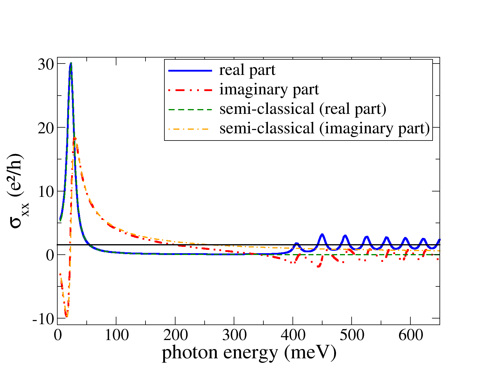
The intraband magneto-peak, Eq.Β (51), is the lowest frequency peak in the absorption spectrum of graphene with EF>E1subscript𝐸𝐹subscript𝐸1E_{F}>E_{1}; its magnitude increases with increasing Fermi energy and/or magnetic field intensity. An example of an intraband absorption line occurring at ω≃ΔωNF\omega\simeq\Delta\omega{}_{N_{F}} is shown in Fig.Β 5. In that case, the parameters correspond to Ξ”=NF22.6\Delta{}_{N_{F}}=22.6Β meV and Ξ“=6.8Ξ“6.8\Gamma=6.8Β meV, and hence Δ≳NFΞ“\Delta{}_{N_{F}}\gtrsim\Gamma. Some points are worth mention: (i) the intraband contribution to the conductivity [Eq.Β (49)] dominates at low photon frequencies; and (ii) the curve for Re​σx​x​(Ο‰)Resubscript𝜎π‘₯π‘₯πœ”\textrm{Re}\,\sigma_{xx}(\omega) shows that the remaining absorption peaks are found in the higher frequency part of the spectrum, above the threshold for interband transitions, ℏ​ωβ‰₯ENF+ENF+1Planck-constant-over-2-piπœ”subscript𝐸subscript𝑁𝐹subscript𝐸subscript𝑁𝐹1\hbar\omega\geq E_{N_{F}}+E_{N_{F}+1}. (Note that, at a low magnetic field and/or high Fermi energy, the level spacing between adjacent LLs is so reduced that ENF≃ENF+1≃EFsimilar-to-or-equalssubscript𝐸subscript𝑁𝐹subscript𝐸subscript𝑁𝐹1similar-to-or-equalssubscript𝐸𝐹E_{N_{F}}\simeq E_{N_{F}+1}\simeq E_{F}, and thus one recovers the condition found earlier, namely, ℏ​ω>2​EFPlanck-constant-over-2-piπœ”2subscript𝐸𝐹\hbar\omega>2E_{F}.) Such interband peaks cause Shubnikov–de Haas oscillations despite the finite electronic density.

For a general relation between the broadening and the energy gap Ξ”NFsubscriptΞ”subscript𝑁𝐹\Delta_{N_{F}}, the maximum for the intraband peak occurs at

Ο‰peakintra=Re​2​Δ​ωNF​Δ​ωNF2+Ξ“2/ℏ2βˆ’Ξ”β€‹Ο‰NF2βˆ’Ξ“2/ℏ2.superscriptsubscriptπœ”peakintraRe2Ξ”subscriptπœ”subscript𝑁𝐹Δsuperscriptsubscriptπœ”subscript𝑁𝐹2superscriptΞ“2superscriptPlanck-constant-over-2-pi2Ξ”superscriptsubscriptπœ”subscript𝑁𝐹2superscriptΞ“2superscriptPlanck-constant-over-2-pi2\omega_{\textrm{peak}}^{\textrm{intra}}=\textrm{Re}\,\sqrt{2\Delta\omega_{N_{F}}\sqrt{\Delta\omega_{N_{F}}^{2}+\Gamma^{2}/\hbar^{2}}-\Delta\omega_{N_{F}}^{2}-\Gamma^{2}/\hbar^{2}}\,. (52)

When Δ​ωNF≀Γ/(3​ℏ)Ξ”subscriptπœ”subscript𝑁𝐹Γ3Planck-constant-over-2-pi\Delta\omega_{N_{F}}\leq\Gamma/(\sqrt{3}\hbar) (typically the case for a very high Fermi energy and/or low magnetic field), the intraband conductivity is maximal at null frequency, with an intensity given by Eq.Β (51) multiplied by a factor of 2.

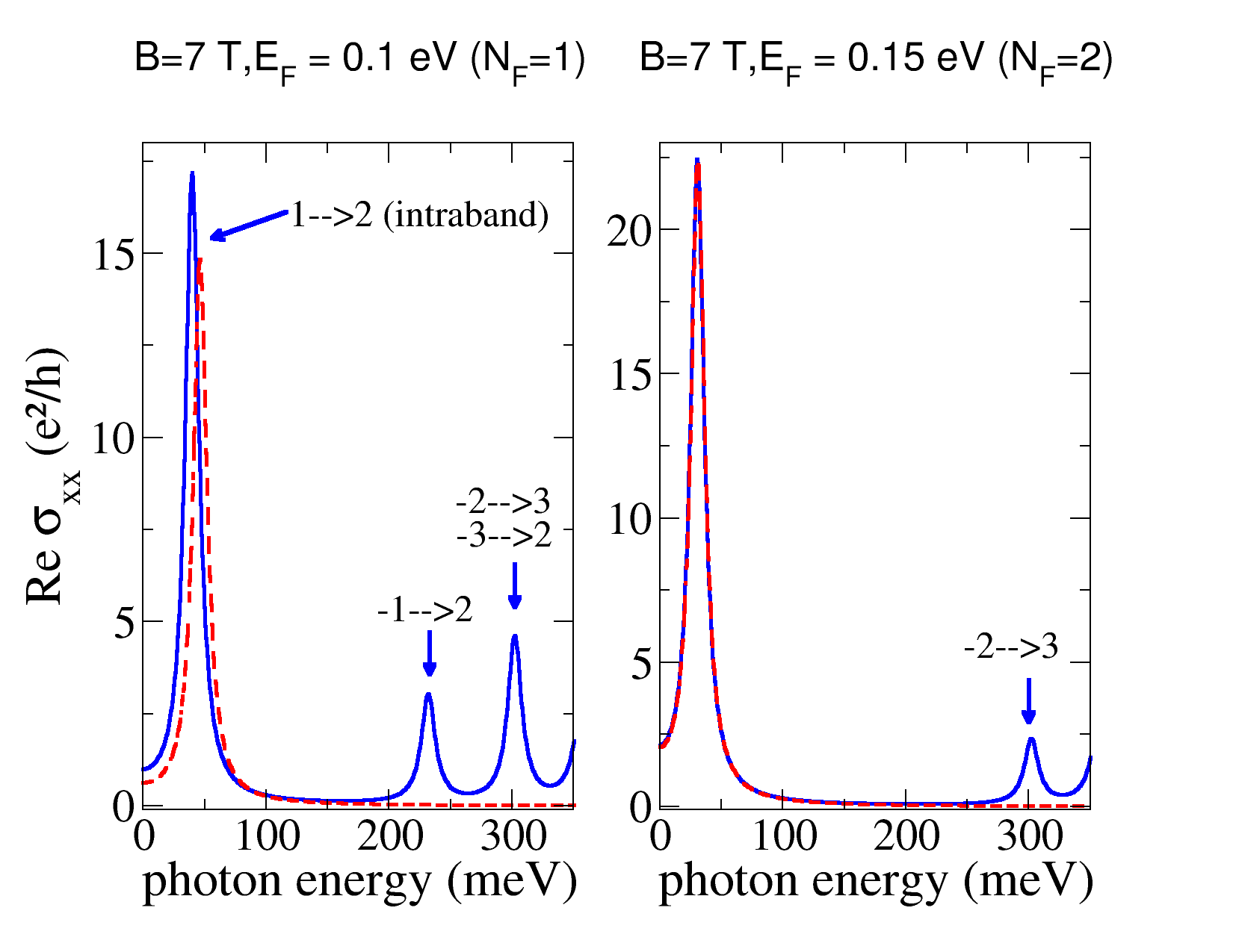
The regime Ξ”NF≲Γless-than-or-similar-tosubscriptΞ”subscript𝑁𝐹Γ\Delta_{N_{F}}\lesssim\Gamma is illustrated in the bottom panel in Fig.Β 12. Two magnetic fields are considered, at a fixed Fermi energy, EF=0.3subscript𝐸𝐹0.3E_{F}=0.3Β eV, with Re​σx​x​(Ο‰)Resubscript𝜎π‘₯π‘₯πœ”\textrm{Re}\>\sigma_{xx}(\omega) being represented by the solid lines. When B=7𝐡7B=7T (left-hand panel), although a considerable number of levels are occupied (NF=9subscript𝑁𝐹9N_{F}=9), one has Ξ”NF≃1.4​Γsimilar-to-or-equalssubscriptΞ”subscript𝑁𝐹1.4Ξ“\Delta_{N_{F}}\simeq 1.4\Gamma, which, according to Eq.Β (52), corresponds to a maximum of the longitudinal conductivity at ω≃Δ​ωNFsimilar-to-or-equalsπœ”Ξ”subscriptπœ”subscript𝑁𝐹\omega\simeq\Delta\omega_{N_{F}}. This is indeed confirmed by the numerical calculation shown there. Decreasing the magnetic field down to B=𝐡absentB=3Β T (right-hand panel), reduces Ξ”NFsubscriptΞ”subscript𝑁𝐹\Delta_{N_{F}} (recall that the LL energy varies as lBβˆ’1∼Bsimilar-tosuperscriptsubscript𝑙𝐡1𝐡l_{B}^{-1}\sim\sqrt{B}), which in turn increases the number of occupied levels to NF=22subscript𝑁𝐹22N_{F}=22. As a consequence, Ξ”NF≃0.67​Γsimilar-to-or-equalssubscriptΞ”subscript𝑁𝐹0.67Ξ“\Delta_{N_{F}}\simeq 0.67\Gamma, and the maximum of the intraband peak is seen to be shifted to zero frequency, again in accordance with Eq.Β (52).

Refer to caption
Figure 5: The longitudinal conductivity as function of the photon energy for EF=0.2subscript𝐸𝐹0.2E_{F}=0.2Β eV. Other parameters as in Fig.Β 4. The solid horizontal (black) line shows graphene’s universal ac-conductivity background [Eq.Β (1)].

Given the intrinsic large cyclotron gap of graphene, E1subscript𝐸1E_{1}, the intraband contribution [Eq. (49)] controls the magneto-optical response of this material in the microwave region up to terahertz (THz) frequencies in samples with a finite electronic density (EF>E1subscript𝐸𝐹subscript𝐸1E_{F}>E_{1}).

The interband contribution, on the other hand, is important both in samples with a low electronic density, EF<E1subscript𝐸𝐹subscript𝐸1E_{F}<E_{1}, where it determines the full magneto-optical response (discarding the effect of phonons as discussed above), and in samples with arbitrary carriers concentrations, for photon energies above the threshold for interband transitions, ℏ​ω=ENF+ENF+1Planck-constant-over-2-piπœ”subscript𝐸subscript𝑁𝐹subscript𝐸subscript𝑁𝐹1\hbar\omega=E_{N_{F}}+E_{N_{F}+1} (typically within the near-infrared region).

The positions of each interband peak can be obtained from Eq.Β (52), with Δ​ωNFΞ”subscriptπœ”subscript𝑁𝐹\Delta\omega_{N_{F}} replaced by

Δ​Ωn=(En+1+En)/ℏ,Ξ”subscriptΩ𝑛subscript𝐸𝑛1subscript𝐸𝑛Planck-constant-over-2-pi\Delta\Omega_{n}=(E_{n+1}+E_{n})/\hbar\,, (53)

with the constraint nβ‰₯NF𝑛subscript𝑁𝐹n\geq N_{F}. At finite electronic densities, NFβ‰₯1subscript𝑁𝐹1N_{F}\geq 1, typically one has ℏ​Δ​Ωn≳Γgreater-than-or-equivalent-toPlanck-constant-over-2-piΞ”subscriptΩ𝑛Γ\hbar\Delta\Omega_{n}\gtrsim\Gamma, and thus we arrive at the following useful approximation

Ο‰peakinter​(n)≃ΔΩn,nβ‰₯NF.\omega_{\textrm{peak}}^{\textrm{inter}\,(n)}\simeq\Delta\Omega_{n}\quad,n\geq N_{F}\,. (54)

For not too small fields, B≳0.1greater-than-or-equivalent-to𝐡0.1B\gtrsim 0.1Β T, the cyclotron gap E1≃36Γ—Bsimilar-to-or-equalssubscript𝐸136𝐡E_{1}\simeq 36\times\sqrt{B}Β meVβ‹…β‹…\cdotT-1/2 is larger than the LL broadening, and thus, in practice, the latter statement can be generalized to include the case of NF=0subscript𝑁𝐹0N_{F}=0.

For general parameters, the intensity of each interband peak is no longer given by a simple expression, because many interband transitions can contribute to the spectral weight close to each of the resonances ω≃Δ​Ωnsimilar-to-or-equalsπœ”Ξ”subscriptΩ𝑛\omega\simeq\Delta\Omega_{n}. As a result, as Ο‰πœ”\omega varies, the real part of Οƒx​x​(Ο‰)subscript𝜎π‘₯π‘₯πœ”\sigma_{xx}(\omega) oscillates around a constant value of about Οƒgsubscript𝜎g\sigma_{\textrm{g}}. Examples are shown in Fig.Β 4 for EF=0subscript𝐸𝐹0E_{F}=0 and in Fig.Β 5 for EF=0.2subscript𝐸𝐹0.2E_{F}=0.2Β eV. In the first case, we have NF=0subscript𝑁𝐹0N_{F}=0 and therefore all the observed peaks are interband-like. The second case has NF=4subscript𝑁𝐹4N_{F}=4 and therefore one intraband peak is observed, corresponding to transitions n=4β†’n=5𝑛4→𝑛5n=4\rightarrow n=5, at low photon energy, whereas the interband peaks appear at energies ℏ​ω≳2​EF=0.4greater-than-or-equivalent-toPlanck-constant-over-2-piπœ”2subscript𝐸𝐹0.4\hbar\omega\gtrsim 2E_{F}=0.4Β eV.

We finally remark that, as long as not too low magnetic fields are considered (B≲0.1less-than-or-similar-to𝐡0.1B\lesssim 0.1Β T), the above considerations are valid even close to room temperature (e.g., for B=1𝐡1B=1Β T, the first LL corresponds to a thermal energy of 420420420Β K).

II.4.3 The Hall conductivity

The Hall optical conductivity of graphene, Οƒx​y​(Ο‰)subscript𝜎π‘₯π‘¦πœ”\sigma_{xy}(\omega), follows directly from Eq.Β (7); choosing i=y𝑖𝑦i=y, j=x𝑗π‘₯j=x, we obtain

Οƒx​y​(Ο‰)=βˆ’gs​gvΓ—J~y​(Ο‰)E~x​(Ο‰),subscript𝜎π‘₯π‘¦πœ”subscript𝑔𝑠subscript𝑔𝑣subscript~π½π‘¦πœ”subscript~𝐸π‘₯πœ”\sigma_{xy}(\omega)=-g_{s}g_{v}\times\frac{\tilde{J}_{y}(\omega)}{\tilde{E}_{x}(\omega)}\,, (55)

where we have invoked graphene’s sixfold crystallographic symmetry to write Οƒx​y​(Ο‰)=βˆ’Οƒy​x​(Ο‰)subscript𝜎π‘₯π‘¦πœ”subscriptπœŽπ‘¦π‘₯πœ”\sigma_{xy}(\omega)=-\sigma_{yx}(\omega). The central quantity to be computed this time is the average value of the current density operator along the y𝑦y direction; using Eqs.Β (6) and (30), we get

Jy​(t)=βˆ’e​vFβ€‹βˆ‘n,nβ€²βŸ¨n,ky|jy|nβ€²,kyβŸ©β€‹βŸ¨c^n,ky†​(t)​c^nβ€²,ky′​(t)⟩.subscript𝐽𝑦𝑑𝑒subscript𝑣𝐹subscript𝑛superscript𝑛′quantum-operator-product𝑛subscriptπ‘˜π‘¦subscript𝑗𝑦superscript𝑛′subscriptπ‘˜π‘¦delimited-⟨⟩superscriptsubscript^𝑐𝑛subscriptπ‘˜π‘¦β€ π‘‘subscript^𝑐superscript𝑛′superscriptsubscriptπ‘˜π‘¦β€²π‘‘J_{y}(t)=-ev_{F}\sum_{n,n^{\prime}}\langle n,k_{y}|j_{y}|n^{\prime},k_{y}\rangle\langle\hat{c}_{n,k_{y}}^{\dagger}(t)\hat{c}_{n^{\prime},k_{y}^{\prime}}(t)\rangle\,. (56)

The non-zero matrix elements read

⟨0,ky|jy|Β±1,ky⟩=quantum-operator-product0subscriptπ‘˜π‘¦subscript𝑗𝑦plus-or-minus1subscriptπ‘˜π‘¦absent\displaystyle\langle 0,k_{y}|j_{y}|\pm 1,k_{y}\rangle= βˆ’i​e​vF2​A,𝑖𝑒subscript𝑣𝐹2𝐴\displaystyle-i\frac{ev_{F}}{\sqrt{2}A}\,, (57)
⟨n,ky|jy|nβ€²,ky⟩=quantum-operator-product𝑛subscriptπ‘˜π‘¦subscript𝑗𝑦superscript𝑛′subscriptπ‘˜π‘¦absent\displaystyle\langle n,k_{y}|j_{y}|n^{\prime},k_{y}\rangle= βˆ’e​vF2​A[sign(nβ€²)Ξ΄|n|βˆ’1,|nβ€²|\displaystyle-\frac{ev_{F}}{2A}\left[\textrm{sign}(n^{\prime})\delta_{|n|-1,|n^{\prime}|}\right.
+sign(n)Ξ΄|n|,|nβ€²|βˆ’1],\displaystyle\left.+\textrm{sign}(n)\delta_{|n|,|n^{\prime}|-1}\right]\,, (58)

(plus respective complex conjugates) where, in the last line, n,nβ€²β‰ 0𝑛superscript𝑛′0n,n^{\prime}\neq 0. Omitting the summation over kysubscriptπ‘˜π‘¦k_{y}, the total current density reads

J^y​(t)subscript^𝐽𝑦𝑑\displaystyle\hat{J}_{y}(t) =i2​A​e​vF​(c1†​a0+v1†​a0βˆ’h.c.)absent𝑖2𝐴𝑒subscript𝑣𝐹superscriptsubscript𝑐1†subscriptπ‘Ž0superscriptsubscript𝑣1†subscriptπ‘Ž0h.c.\displaystyle=\frac{i}{\sqrt{2}A}ev_{F}\left(c_{1}^{\dagger}a_{0}+v_{1}^{\dagger}a_{0}-\textrm{h.c.}\right)
βˆ’12​A​e​vFβ€‹βˆ‘nβ‰₯1(P^n(1)βˆ’P^n(2)+h.c.)12𝐴𝑒subscript𝑣𝐹subscript𝑛1superscriptsubscript^𝑃𝑛1superscriptsubscript^𝑃𝑛2h.c.\displaystyle-\frac{1}{2A}ev_{F}\sum_{n\geq 1}\left(\hat{P}_{n}^{(1)}-\hat{P}_{n}^{(2)}+\textrm{h.c.}\right)
βˆ’12​A​e​vFβ€‹βˆ‘nβ‰₯1(cn†​cn+1βˆ’vn†​vn+1+h.c.).12𝐴𝑒subscript𝑣𝐹subscript𝑛1superscriptsubscript𝑐𝑛†subscript𝑐𝑛1superscriptsubscript𝑣𝑛†subscript𝑣𝑛1h.c.\displaystyle-\frac{1}{2A}ev_{F}\sum_{n\geq 1}\left(c_{n}^{\dagger}c_{n+1}-v_{n}^{\dagger}v_{n+1}+\textrm{h.c.}\right). (59)

The EOMs resemble those derived for the longitudinal conductivity [Eqs.Β (39)-(40)], the reason being that the current matrix elements in the xπ‘₯x and y𝑦y directions are the same except for phase factors [compare Eqs.Β (32) and (33) with Eqs.Β (57) and (58)]. The final formula (after regularization) yields,

Οƒx​yreg​(Ο‰)=e2hβ€‹βˆ‘nβ‰ m=βˆ’NcNcΞ›n​mx​yi​En​m​nF​(En)βˆ’nF​(Em)ℏ​ω+En​m+i​Γ,superscriptsubscript𝜎π‘₯𝑦regπœ”superscript𝑒2β„Žsuperscriptsubscriptπ‘›π‘šsubscript𝑁𝑐subscript𝑁𝑐superscriptsubscriptΞ›π‘›π‘šπ‘₯𝑦𝑖subscriptπΈπ‘›π‘šsubscript𝑛𝐹subscript𝐸𝑛subscript𝑛𝐹subscriptπΈπ‘šPlanck-constant-over-2-piπœ”subscriptπΈπ‘›π‘šπ‘–Ξ“\sigma_{xy}^{\textrm{reg}}(\omega)=\frac{e^{2}}{h}\sum_{n\neq m=-N_{c}}^{N_{c}}\frac{\Lambda_{nm}^{xy}}{iE_{nm}}\frac{n_{F}(E_{n})-n_{F}(E_{m})}{\hbar\omega+E_{nm}+i\Gamma}\,, (60)

with matrix elements Ξ›m​nx​ysuperscriptsubscriptΞ›π‘šπ‘›π‘₯𝑦\Lambda_{mn}^{xy} related to Ξ›n​mx​xsuperscriptsubscriptΞ›π‘›π‘šπ‘₯π‘₯\Lambda_{nm}^{xx} [Eq.Β (47)] according to,

Ξ›n​mx​y=i​Λn​mx​x​(Ξ΄|m|,|n|βˆ’1βˆ’Ξ΄|m|βˆ’1,|n|).superscriptsubscriptΞ›π‘›π‘šπ‘₯𝑦𝑖superscriptsubscriptΞ›π‘›π‘šπ‘₯π‘₯subscriptπ›Ώπ‘šπ‘›1subscriptπ›Ώπ‘š1𝑛\Lambda_{nm}^{xy}=i\Lambda_{nm}^{xx}(\delta_{|m|,|n|-1}-\delta_{|m|-1,|n|})\,. (61)

Likewise Οƒx​x​(Ο‰)subscript𝜎π‘₯π‘₯πœ”\sigma_{xx}(\omega), the result for the Hall conductivity based on the EOM method coincides with the result obtained using Green functions calculations.CarbotteIJMP2007
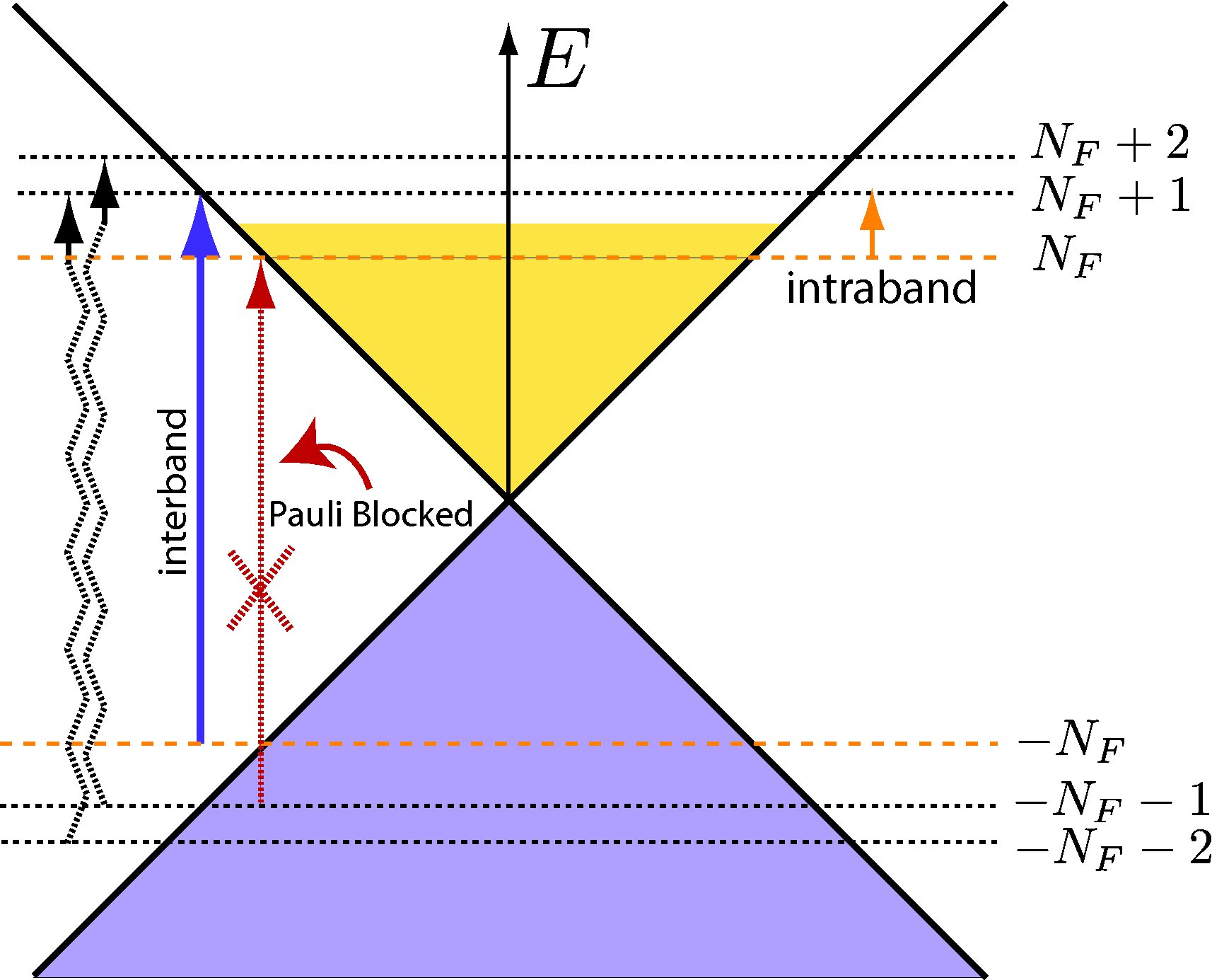
Refer to caption
Figure 6: Schematic of electronic transitions contributing to the Hall conductivity of doped graphene in a magnetic field. Contrary to the longitudinal conductivity (Fig.Β 3), symmetry implies that only interband transitions involving the smallest energy difference, ℏ​Δ​ΩNF=ENF+ENF+1Planck-constant-over-2-piΞ”subscriptΞ©subscript𝑁𝐹subscript𝐸subscript𝑁𝐹subscript𝐸subscript𝑁𝐹1\hbar\Delta\Omega_{N_{F}}=E_{N_{F}}+E_{N_{F}+1}, contribute to Οƒx​ysubscript𝜎π‘₯𝑦\sigma_{xy}. The remaining interband transitions (Δ​ΩnΞ”subscriptΩ𝑛\Delta\Omega_{n}, with n>NF𝑛subscript𝑁𝐹n>N_{F}) come in pairs whose contribution to the Hall current mutually cancel as explained in the text: an example of a pair of interband transitions that cancel is shown in zig-zag arrows. Note: The schematic picture is strictly adequate for NFβ‰₯1subscript𝑁𝐹1N_{F}\geq 1; the case of NF=0subscript𝑁𝐹0N_{F}=0 admits a single type of electronic transition, namely, n=0β†’n=1𝑛0→𝑛1n=0\rightarrow n=1.

Symmetry considerations imply that only two terms contribute in general for the zero-temperature Hall conductivity, and hence the formula Eq.Β (60) can be considerably simplified. The first term is the intraband contribution and reads,

Οƒx​yintra​(Ο‰)=e2h​2​ℏ2​vF2lB2​1βˆ’Ξ΄NF,0(ℏ​ω+i​Γ)2βˆ’β„2​Δ​ωNF2,superscriptsubscript𝜎π‘₯𝑦intraπœ”superscript𝑒2β„Ž2superscriptPlanck-constant-over-2-pi2superscriptsubscript𝑣𝐹2superscriptsubscript𝑙𝐡21subscript𝛿subscript𝑁𝐹0superscriptPlanck-constant-over-2-piπœ”π‘–Ξ“2superscriptPlanck-constant-over-2-pi2Ξ”superscriptsubscriptπœ”subscript𝑁𝐹2\sigma_{xy}^{\textrm{intra}}(\omega)=\frac{e^{2}}{h}\frac{2\hbar^{2}v_{F}^{2}}{l_{B}^{2}}\frac{1-\delta_{N_{F},0}}{\left(\hbar\omega+i\Gamma\right)^{2}-\hbar^{2}\Delta\omega_{N_{F}}^{2}}\,, (62)

and the second is interband-like, connecting electronic states with n=βˆ’NF𝑛subscript𝑁𝐹n=-N_{F} and n=NF+1𝑛subscript𝑁𝐹1n=N_{F}+1, and reads,

Οƒx​yinter​(Ο‰)=e2h​2​ℏ2​vF2lB2​1+Ξ΄NF,0(ℏ​ω+i​Γ)2βˆ’β„2​Δ​ΩNF2.superscriptsubscript𝜎π‘₯𝑦interπœ”superscript𝑒2β„Ž2superscriptPlanck-constant-over-2-pi2superscriptsubscript𝑣𝐹2superscriptsubscript𝑙𝐡21subscript𝛿subscript𝑁𝐹0superscriptPlanck-constant-over-2-piπœ”π‘–Ξ“2superscriptPlanck-constant-over-2-pi2Ξ”superscriptsubscriptΞ©subscript𝑁𝐹2\sigma_{xy}^{\textrm{inter}}(\omega)=\frac{e^{2}}{h}\frac{2\hbar^{2}v_{F}^{2}}{l_{B}^{2}}\frac{1+\delta_{N_{F},0}}{\left(\hbar\omega+i\Gamma\right)^{2}-\hbar^{2}\Delta\Omega_{N_{F}}^{2}}\,. (63)

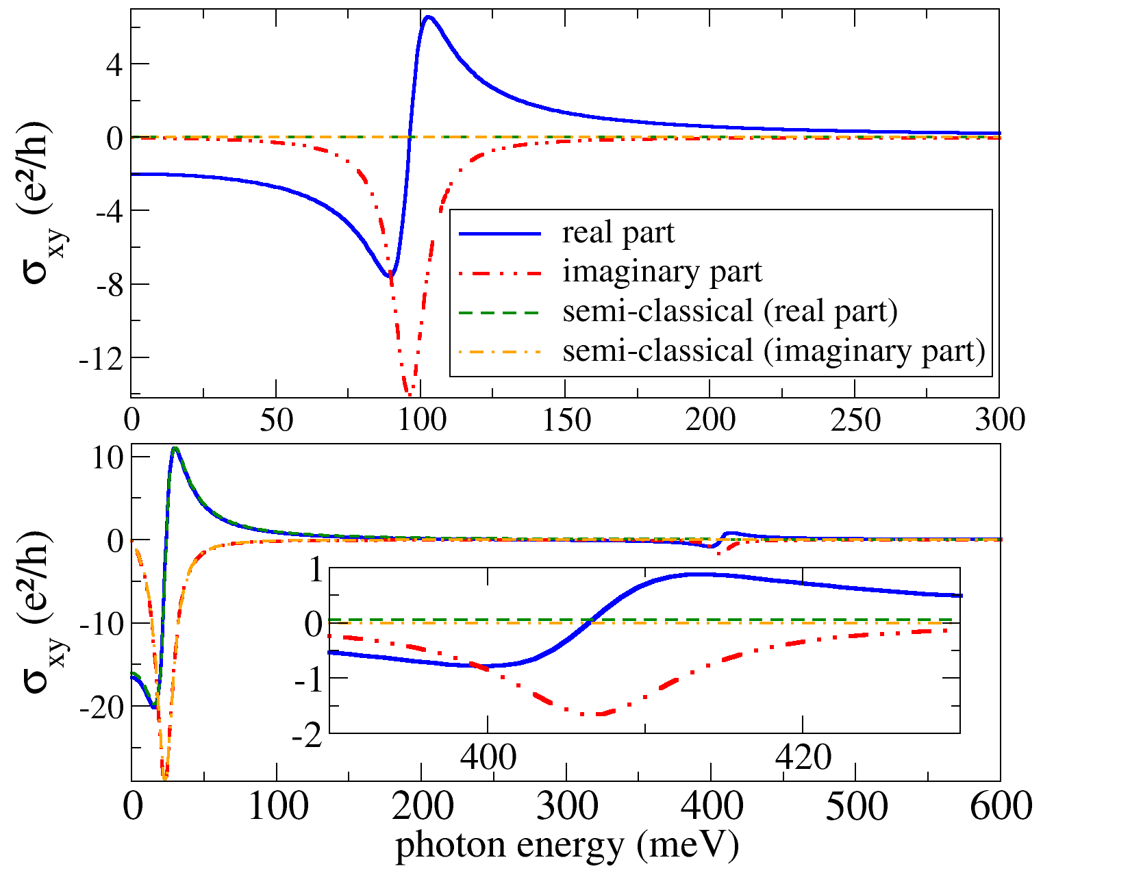
A single interband transition play a role in setting the Hall conductivity, even for zero Fermi energy. This is at odds with the situation for Οƒx​x​(Ο‰)subscript𝜎π‘₯π‘₯πœ”\sigma_{xx}(\omega), where many non equivalent interband transitions contribute to the optical spectral weight. To understand this peculiar feature of Οƒx​y​(Ο‰)subscript𝜎π‘₯π‘¦πœ”\sigma_{xy}(\omega), let us consider the second lowest interband resonant energy, namely, Δ​E2=ENF+2βˆ’Eβˆ’NFβˆ’1Ξ”subscript𝐸2subscript𝐸subscript𝑁𝐹2subscript𝐸subscript𝑁𝐹1\Delta E_{2}=E_{N_{F}+2}-E_{-N_{F}-1}: there are two distinct sorts of interband transitions nβ†’mβ†’π‘›π‘šn\rightarrow m involving such energy difference, namely, the pair n1=βˆ’NFβˆ’2∧m1=NF+1subscript𝑛1subscript𝑁𝐹2subscriptπ‘š1subscript𝑁𝐹1n_{1}=-N_{F}-2\,\wedge\,m_{1}=N_{F}+1 and n2=βˆ’NFβˆ’1∧m2=NF+2subscript𝑛2subscript𝑁𝐹1subscriptπ‘š2subscript𝑁𝐹2n_{2}=-N_{F}-1\,\wedge\,m_{2}=N_{F}+2, whose Hall matrix elements read, Ξ›n1​m1x​y=i​Λn1​m1x​xsuperscriptsubscriptΞ›subscript𝑛1subscriptπ‘š1π‘₯𝑦𝑖superscriptsubscriptΞ›subscript𝑛1subscriptπ‘š1π‘₯π‘₯\Lambda_{n_{1}m_{1}}^{xy}=i\Lambda_{n_{1}m_{1}}^{xx} and Ξ›n2​m2x​y=βˆ’i​Λn2​m2x​xsuperscriptsubscriptΞ›subscript𝑛2subscriptπ‘š2π‘₯𝑦𝑖superscriptsubscriptΞ›subscript𝑛2subscriptπ‘š2π‘₯π‘₯\Lambda_{n_{2}m_{2}}^{xy}=-i\Lambda_{n_{2}m_{2}}^{xx}, respectively. When substituting into Eq.Β (60), these contributions cancel each other at T=0𝑇0T=0 because Ξ›n2​m2x​x=Ξ›n1​m1x​xsuperscriptsubscriptΞ›subscript𝑛2subscriptπ‘š2π‘₯π‘₯superscriptsubscriptΞ›subscript𝑛1subscriptπ‘š1π‘₯π‘₯\Lambda_{n_{2}m_{2}}^{xx}=\Lambda_{n_{1}m_{1}}^{xx}. The same argument applies to all transitions involving an energy difference larger than the interband gap, ℏ​Δ​ΩNFPlanck-constant-over-2-piΞ”subscriptΞ©subscript𝑁𝐹\hbar\Delta\Omega_{N_{F}}. The only exception is indeed the interband transition βˆ’NFβ†’NF+1β†’subscript𝑁𝐹subscript𝑁𝐹1-N_{F}\rightarrow N_{F}+1 because, contrary to interband transitions involving larger energy differences, it cannot be canceled by the other member of the pair, n=βˆ’NFβˆ’1∧m=NF𝑛subscript𝑁𝐹1π‘šsubscript𝑁𝐹n=-N_{F}-1\wedge m=N_{F}, since the latter is forbidden via Pauli blockade; a schematic picture is given in Fig.Β 6.

The extremum points of the real part of the Hall conductivity occurs at zero frequency, Ο‰=0πœ”0\omega=0, and

ω±intra≃similar-to-or-equalssuperscriptsubscriptπœ”plus-or-minusintraabsent\displaystyle\omega_{\pm}^{\textrm{intra}}\simeq Δ​ωNFΒ±Ξ“/ℏ,plus-or-minusΞ”subscriptπœ”subscript𝑁𝐹ΓPlanck-constant-over-2-pi\displaystyle\Delta\omega_{N_{F}}\pm\Gamma/\hbar\,, (64)
ω±inter≃similar-to-or-equalssuperscriptsubscriptπœ”plus-or-minusinterabsent\displaystyle\omega_{\pm}^{\textrm{inter}}\simeq Δ​ΩNFΒ±Ξ“/ℏ,plus-or-minusΞ”subscriptΞ©subscript𝑁𝐹ΓPlanck-constant-over-2-pi\displaystyle\Delta\Omega_{N_{F}}\pm\Gamma/\hbar\,, (65)

where we have considered Ξ“/ℏ≲Δ​ωNFless-than-or-similar-toΞ“Planck-constant-over-2-piΞ”subscriptπœ”subscript𝑁𝐹\Gamma/\hbar\lesssim\Delta\omega_{N_{F}} [see Eq.Β (51) and text therein] and made use of Ξ“/ℏβ‰ͺΔ​ΩNFmuch-less-thanΞ“Planck-constant-over-2-piΞ”subscriptΞ©subscript𝑁𝐹\Gamma/\hbar\ll\Delta\Omega_{N_{F}}. The latter consideration is true in virtually all situations except for graphene at a low electronic density and small magnetic field B𝐡B. Within the same accuracy, the Hall conductivity at Ο‰=0πœ”0\omega=0 reads

Re​σx​y​(0)β‰ƒβˆ’(1βˆ’Ξ΄NF,0Δ​ωNF2+1+Ξ΄NF,0Δ​ΩNF2)​(4​e​B​vF2ℏ​π)Γ—Οƒg,similar-to-or-equalsResubscript𝜎π‘₯𝑦01subscript𝛿subscript𝑁𝐹0Ξ”superscriptsubscriptπœ”subscript𝑁𝐹21subscript𝛿subscript𝑁𝐹0Ξ”superscriptsubscriptΞ©subscript𝑁𝐹24𝑒𝐡superscriptsubscript𝑣𝐹2Planck-constant-over-2-piπœ‹subscript𝜎g\textrm{Re}\,\sigma_{xy}(0)\simeq-\left(\frac{1-\delta_{N_{F},0}}{\Delta\omega_{N_{F}}^{2}}+\frac{1+\delta_{N_{F},0}}{\Delta\Omega_{N_{F}}^{2}}\right)\left(\frac{4eBv_{F}^{2}}{\hbar\pi}\right)\times\sigma_{\textrm{g}}\,, (66)

whereas at the point ω±intrasuperscriptsubscriptπœ”plus-or-minusintra\omega_{\pm}^{\textrm{intra}} it is given by

Re​σx​y​(ω±intra)≃FΔ​ωNF±​(1βˆ’Ξ΄NF,0Δ​ωNF)​(e​B​vF2π​Γ)Γ—Οƒg,similar-to-or-equalsResubscript𝜎π‘₯𝑦superscriptsubscriptπœ”plus-or-minusintrasuperscriptsubscript𝐹Δsubscriptπœ”subscript𝑁𝐹plus-or-minus1subscript𝛿subscript𝑁𝐹0Ξ”subscriptπœ”subscript𝑁𝐹𝑒𝐡superscriptsubscript𝑣𝐹2πœ‹Ξ“subscript𝜎g\textrm{Re}\,\sigma_{xy}(\omega_{\pm}^{\textrm{intra}})\simeq F_{\Delta\omega_{N_{F}}}^{\pm}\left(\frac{1-\delta_{N_{F},0}}{\Delta\omega_{N_{F}}}\right)\left(\frac{eBv_{F}^{2}}{\pi\Gamma}\right)\times\sigma_{\textrm{g}}\,, (67)

and for ω±intersuperscriptsubscriptπœ”plus-or-minusinter\omega_{\pm}^{\textrm{inter}} it reads

Re​σx​y​(ω±inter)≃FΔ​ΩNF±​(1+Ξ΄NF,0Δ​ΩNF)​(e​B​vF2π​Γ)Γ—Οƒg,similar-to-or-equalsResubscript𝜎π‘₯𝑦superscriptsubscriptπœ”plus-or-minusintersuperscriptsubscript𝐹ΔsubscriptΞ©subscript𝑁𝐹plus-or-minus1subscript𝛿subscript𝑁𝐹0Ξ”subscriptΞ©subscript𝑁𝐹𝑒𝐡superscriptsubscript𝑣𝐹2πœ‹Ξ“subscript𝜎g\textrm{Re}\,\sigma_{xy}(\omega_{\pm}^{\textrm{inter}})\simeq F_{\Delta\Omega_{N_{F}}}^{\pm}\left(\frac{1+\delta_{N_{F},0}}{\Delta\Omega_{N_{F}}}\right)\left(\frac{eBv_{F}^{2}}{\pi\Gamma}\right)\times\sigma_{\textrm{g}}\,, (68)

where we have defined Fω±=±ℏ​ω/(ℏ​ω±Γ)superscriptsubscriptπΉπœ”plus-or-minusplus-or-minusPlanck-constant-over-2-piπœ”plus-or-minusPlanck-constant-over-2-piπœ”Ξ“F_{\omega}^{\pm}=\pm\hbar\omega/(\hbar\omega\pm\Gamma). The intensity of the Hall peaks dependence on the magnetic field intensity B𝐡B is the same as for the longitudinal (intraband) peaks [Eq.Β (51)], i.e., as ∼Bsimilar-toabsent𝐡\sim\sqrt{B}. Also, similarly to Οƒx​x​(Ο‰)subscript𝜎π‘₯π‘₯πœ”\sigma_{xx}(\omega), in doped graphene with NF>1subscript𝑁𝐹1N_{F}>1, the interband peak is very low compared with the intraband Hall peak for Δ​ωNFβ‰ͺΔ​ΩNFmuch-less-thanΞ”subscriptπœ”subscript𝑁𝐹ΔsubscriptΞ©subscript𝑁𝐹\Delta\omega_{N_{F}}\ll\Delta\Omega_{N_{F}}. We, finally, remark that the anomaly associated with the zero energy LL is present in all the latter expressions via the factor 1+Ξ΄NF,01subscript𝛿subscript𝑁𝐹01+\delta_{N_{F},0}.

FigureΒ 7 shows the Hall conductivity of graphene at a high magnetic field (B=7𝐡7B=7Β T) for NF=0subscript𝑁𝐹0N_{F}=0 (top) and NF=4subscript𝑁𝐹4N_{F}=4 (bottom), corresponding to neutral and highly doped graphene samples, respectively. The main characteristics of Re​σx​y​(Ο‰)Resubscript𝜎π‘₯π‘¦πœ”\textrm{Re}\,\sigma_{xy}(\omega) can be explained using Eqs.Β (66)-(68). In particular, for doped graphene, the spectral weight concentrates around two well-separated parts of the spectrum: (i) an intraband-dominated region (n=4β†’n=5𝑛4→𝑛5n=4\rightarrow n=5 ), at low photon energies, with a maximum (minimum) intensity occurring at ℏ​ω+≃Δ4+Γ≃30similar-to-or-equalsPlanck-constant-over-2-pisubscriptπœ”subscriptΞ”4Ξ“similar-to-or-equals30\hbar\omega_{+}\simeq\Delta_{4}+\Gamma\simeq 30Β meV (β„β€‹Ο‰βˆ’β‰ƒΞ”4βˆ’Ξ“β‰ƒ16similar-to-or-equalsPlanck-constant-over-2-pisubscriptπœ”subscriptΞ”4Ξ“similar-to-or-equals16\hbar\omega_{-}\simeq\Delta_{4}-\Gamma\simeq 16Β meV ) [intensity equal to ≃10​e2/hsimilar-to-or-equalsabsent10superscript𝑒2β„Ž\simeq 10e^{2}/h (β‰ƒβˆ’20​e2/hsimilar-to-or-equalsabsent20superscript𝑒2β„Ž\simeq-20e^{2}/h), in accordance with Eq.Β (67)], and (ii) an interband-dominated region n=βˆ’4β†’n=5𝑛4→𝑛5n=-4\rightarrow n=5, at high photon energies, with a maximum (minimum) intensity occurring at ℏ​Ω+≃ℏ​Δ​Ω4+Γ≃413similar-to-or-equalsPlanck-constant-over-2-pisubscriptΞ©Planck-constant-over-2-piΞ”subscriptΞ©4Ξ“similar-to-or-equals413\hbar\Omega_{+}\simeq\hbar\Delta\Omega_{4}+\Gamma\simeq 413Β meV (β„β€‹Ξ©βˆ’β‰ƒβ„β€‹Ξ”β€‹Ξ©4βˆ’Ξ“β‰ƒ400similar-to-or-equalsPlanck-constant-over-2-pisubscriptΞ©Planck-constant-over-2-piΞ”subscriptΞ©4Ξ“similar-to-or-equals400\hbar\Omega_{-}\simeq\hbar\Delta\Omega_{4}-\Gamma\simeq 400Β meV) [intensity equal to ≃0.81​e2/hsimilar-to-or-equalsabsent0.81superscript𝑒2β„Ž\simeq 0.81e^{2}/h (β‰ƒβˆ’0.85​e2/hsimilar-to-or-equalsabsent0.85superscript𝑒2β„Ž\simeq-0.85e^{2}/h), in accordance with Eq.Β (68)].

Refer to caption
Figure 7: Hall conductivity as a function of photon energy for EF=0subscript𝐸𝐹0E_{F}=0 (top) and EF=0.2subscript𝐸𝐹0.2E_{F}=0.2Β eV (bottom). In both plots T=0𝑇0T=0 (other parameters as in Fig.Β 4). At zero Fermi energy (top), Οƒx​y​(Ο‰)subscript𝜎π‘₯π‘¦πœ”\sigma_{xy}(\omega) originates in a single type of interband transition, centered at β„β€‹Ο‰β‰ˆE1≃96Planck-constant-over-2-piπœ”subscript𝐸1similar-to-or-equals96\hbar\omega\approx E_{1}\simeq 96Β meV, and therefore cannot be described by a semi-classical treatment [Eq.Β (63)]. When EF=0.2subscript𝐸𝐹0.2E_{F}=0.2Β eV (bottom), the first four LLs are fulfilled, which results in a classical intraband contribution [Eq.Β (62)], centered at ℏ​ω≃E5βˆ’E4β‰ˆ23similar-to-or-equalsPlanck-constant-over-2-piπœ”subscript𝐸5subscript𝐸423\hbar\omega\simeq E_{5}-E_{4}\thickapprox 23Β meV, and a single interband transition [Eq.Β (63)] centered at ℏ​ω≃E5+E4β‰ˆ0.4similar-to-or-equalsPlanck-constant-over-2-piπœ”subscript𝐸5subscript𝐸40.4\hbar\omega\simeq E_{5}+E_{4}\thickapprox 0.4Β eV ≃2​EFsimilar-to-or-equalsabsent2subscript𝐸𝐹\simeq 2E_{F}. The latter is shown in the inset.

Dependence on the Fermi energyβ€”The variation of conductivity with the Fermi energy reveals other peculiar feature of 2D systems: Hall quantization.vonKlitzing ; Thouless_IQHE FigureΒ 8 shows the formation of plateau in the static (or dc) Hall conductivity, Οƒx​y​(0)subscript𝜎π‘₯𝑦0\sigma_{xy}(0), a direct evidence for discrete energy levels. In conventional 2D electron gases, the widths of such plateau are constant (the LLs energy scales as n𝑛n), whereas in graphene the plateau’s width decreases with increasing Fermi energy (the LLs energy scales as n𝑛\sqrt{n}). As for the steps heights, they are equidistant in graphene, Δ​σx​y​(0)=4​e2/hΞ”subscript𝜎π‘₯𝑦04superscript𝑒2β„Ž\Delta\sigma_{xy}(0)=4e^{2}/h, even when crossing EF=0subscript𝐸𝐹0E_{F}=0, whereas in conventional 2D systems the step from the first electron LL (n=1𝑛1n=1) and the first hole LL (n=βˆ’1𝑛1n=-1) is twice the value of the remaining steps (a manifestation of the zero-energy LL graphene anomaly).

The Hall conductivity quantization rule for graphene can be readily obtained by adding the intraband and interband Hall conductivities,

Οƒx​y​(0)=βˆ’4​e2h​(NF+12),subscript𝜎π‘₯𝑦04superscript𝑒2β„Žsubscript𝑁𝐹12\sigma_{xy}(0)=-\frac{4e^{2}}{h}\left(N_{F}+\frac{1}{2}\right)\,, (69)

where we have used Ξ“β‰ͺE1much-less-thanΞ“subscript𝐸1\Gamma\ll E_{1} in order to simplify the denominators of Eqs.Β (62) and (63). Despite the filling factor, Ξ½=4​NF+2𝜈4subscript𝑁𝐹2\nu=4N_{F}+2, being an integer number, there is no complete correspondence with the conventional 2D IQHE, for which Οƒx​y=βˆ’4​e2​NF/hsubscript𝜎π‘₯𝑦4superscript𝑒2subscriptπ‘πΉβ„Ž\sigma_{xy}=-4e^{2}N_{F}/h; an extra 1/2121/2 factor due to the contribution of the zero-energy state, shared by both electrons and holes, shows up, which must be taken separately, making ν𝜈\nu always evenβ€”this is known as the anomalous IQHE and is a hallmark of chiral massless fermions. The anomalous IQHE was predicted theoreticallyAnamQHE_Sharapov05 ; Peres 2006 and measuredNovoselov 2005 ; PKim2005 in the early days of graphene.
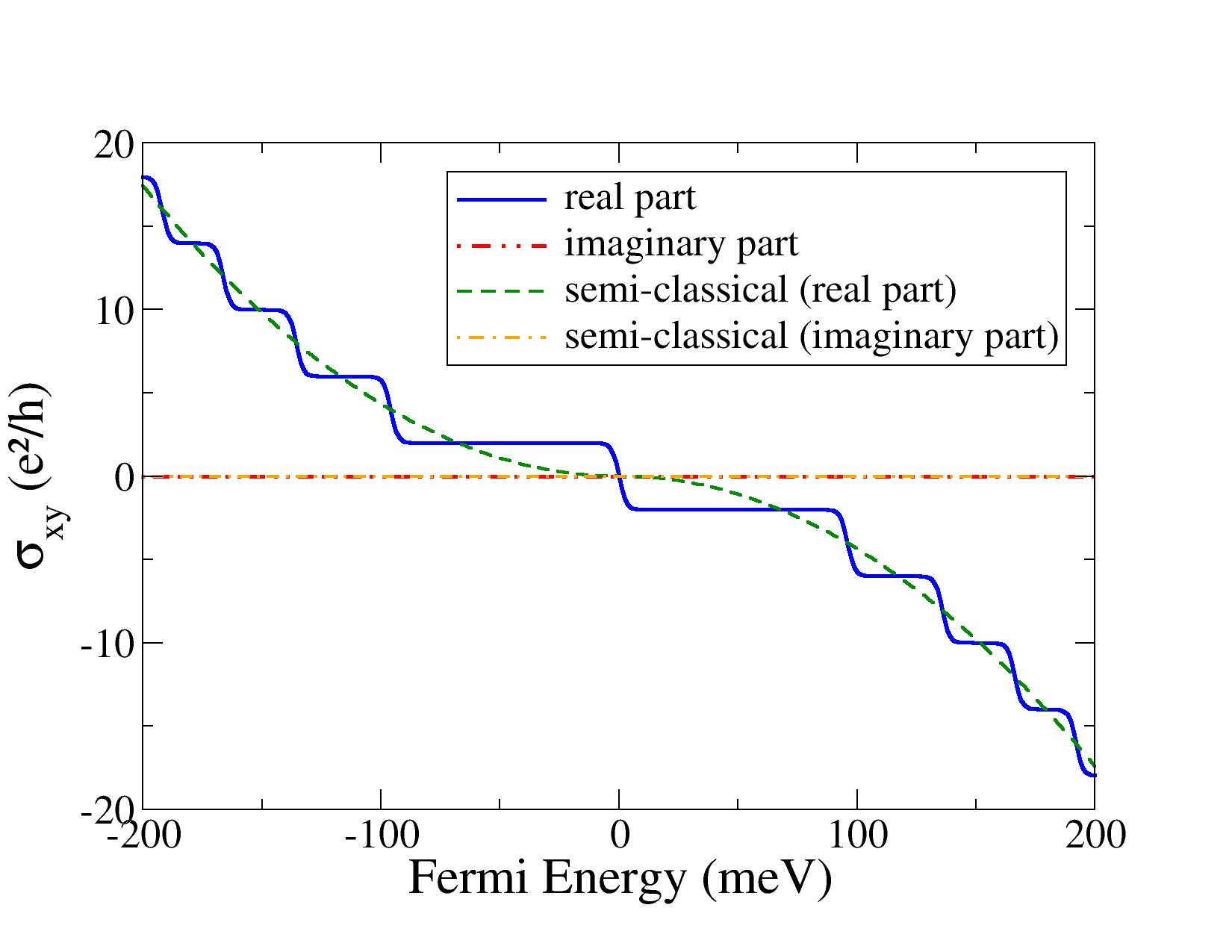
Refer to caption
Figure 8: The dc Hall conductivity as a function of the Fermi energy. The parameters are T=17𝑇17T=17Β K and Ξ“=0.68Ξ“0.68\Gamma=0.68Β meV. The plateaux show Hall quantization values according to the theoretical prediction for massless Dirac fermions [Eq.Β (69)].

II.5 The semiclassical solution

Within the semiclassical approach, the spinorial nature of the electrons’ wave function is immaterial. On the other hand, the massless nature of the spectrum invalidates a straightforward Drude-like approach Ziman ; Mermin to the calculation of the transport coefficients, and Boltzmann transport theory is required, since in this formulation the central quantity to be computed is the deviation of the momentum distribution function from the equilibrium Fermi distribution.

In the semiclassical regime (that is, a high electronic density and/or low magnetic fields), the physics of the Hall effect can be explained in terms of Boltzmann’s theory of transport, where the electric current is given, in the case of graphene, by:

𝑱=e2hβ€‹βˆ«π‘‘π€β€‹g​(B,𝐀,Ο‰)​𝒗𝐀,𝑱superscript𝑒2β„Ždifferential-dπ€π‘”π΅π€πœ”subscript𝒗𝐀\bm{J}=\frac{e^{2}}{h}\int d\mathbf{k}g(B,\mathbf{k},\omega)\bm{v}_{\mathbf{k}}\,, (70)

with spin and valley degeneracies included, and where g​(B,𝐀,Ο‰)≑gπ€π‘”π΅π€πœ”subscript𝑔𝐀g(B,\mathbf{k},\omega)\equiv g_{\mathbf{k}}, is the deviation of the carriers’ (electrons or holes) distribution function from the equilibrium Fermi distribution, f0​(Ο΅)subscript𝑓0italic-Ο΅f_{0}(\epsilon), e𝑒e is the charge of the carrier, the static magnetic field B𝐡B is considered to be perpendicular to graphene’s surface, Ο‰πœ”\omega is the frequency of the electromagnetic field, and the carrier’s velocity reads 𝒗𝐀=(vx,vy)=vF​(cos⁑θ,sin⁑θ)subscript𝒗𝐀subscript𝑣π‘₯subscript𝑣𝑦subscriptπ‘£πΉπœƒπœƒ\bm{v}_{\mathbf{k}}=(v_{x},v_{y})=v_{F}(\cos\theta,\sin\theta). In the presence of both an electric and a magnetic field, the distribution g𝐀subscript𝑔𝐀g_{\mathbf{k}} is the solution of the equationZiman

βˆ’eβ€‹π„β‹…π’—π€β€‹βˆ‚f0βˆ‚Ο΅=g𝐀τ𝐀+βˆ‚gπ€βˆ‚t+eℏ​(𝒗𝐀×𝐁)β‹…βˆ‡π€g𝐀,⋅𝑒𝐄subscript𝒗𝐀subscript𝑓0italic-Ο΅subscript𝑔𝐀subscript𝜏𝐀subscript𝑔𝐀𝑑⋅𝑒Planck-constant-over-2-pisubscript𝒗𝐀𝐁subscriptβˆ‡π€subscript𝑔𝐀-e\mathbf{E}\cdot\bm{v}_{\mathbf{k}}\frac{\partial f_{0}}{\partial\epsilon}=\frac{g_{\mathbf{k}}}{\tau_{\mathbf{k}}}+\frac{\partial g_{\mathbf{k}}}{\partial t}+\frac{e}{\hbar}\left(\bm{v}_{\mathbf{k}}\times\mathbf{B}\right)\cdot\nabla_{\mathbf{k}}g_{\mathbf{k}}\,, (71)

where we have employed the the standard relaxation approximation,Ziman i.e.,

βˆ‚fπ€βˆ‚t|scatt=βˆ’g𝐀τ𝐀,evaluated-atsubscript𝑓𝐀𝑑scattsubscript𝑔𝐀subscript𝜏𝐀\left.\frac{\partial f_{\mathbf{k}}}{\partial t}\right|_{\textrm{scatt}}=-\frac{g_{\mathbf{k}}}{\tau_{\mathbf{k}}}\,, (72)

where τ𝐀subscript𝜏𝐀\tau_{\mathbf{k}} is the relaxation scattering time, 𝐄=(E0,x,E0,y)𝐄subscript𝐸0π‘₯subscript𝐸0𝑦\mathbf{E}=(E_{0,x},E_{0,y}) is the electric field, and βˆ‡π€subscriptβˆ‡π€\nabla_{\mathbf{k}} is the gradient operator with respect to the momentum 𝐀𝐀\mathbf{k}. Writing g𝐀subscript𝑔𝐀g_{\mathbf{k}} as,

g𝐀=eβˆ’i​ω​t​𝐀⋅𝐀,subscript𝑔𝐀⋅superscriptπ‘’π‘–πœ”π‘‘π€π€g_{\mathbf{k}}=e^{-i\omega t}\mathbf{k}\cdot\mathbf{A}\,, (73)

and noting that (𝒗𝐀×𝐁)β‹…βˆ‡π€g𝐀=𝒗𝐀⋅(πΓ—βˆ‡π€g𝐀)β‹…subscript𝒗𝐀𝐁subscriptβˆ‡π€subscript𝑔𝐀⋅subscript𝒗𝐀𝐁subscriptβˆ‡π€subscript𝑔𝐀(\bm{v}_{\mathbf{k}}\times\mathbf{B})\cdot\nabla_{\mathbf{k}}g_{\mathbf{k}}=\bm{v}_{\mathbf{k}}\cdot(\mathbf{B}\times\nabla_{\mathbf{k}}g_{\mathbf{k}}), Eq.Β (71) can be solved exactly, where the vector 𝐀𝐀\mathbf{A} needs to be determined. Solving Eq.Β (71), the components of the vector A=(Ax,Ay)𝐴subscript𝐴π‘₯subscript𝐴𝑦A=(A_{x},A_{y}) are obtained in the form

Axsubscript𝐴π‘₯\displaystyle A_{x} =(1βˆ’i​ω​τ𝐀)​Exβˆ’Ο„π€β€‹Ο‰c​Ey(1βˆ’i​ω​τ𝐀)2+Ο‰c2​τ𝐀2,absent1π‘–πœ”subscript𝜏𝐀subscript𝐸π‘₯subscript𝜏𝐀subscriptπœ”π‘subscript𝐸𝑦superscript1π‘–πœ”subscript𝜏𝐀2superscriptsubscriptπœ”π‘2superscriptsubscript𝜏𝐀2\displaystyle=\frac{(1-i\omega\tau_{\mathbf{k}})E_{x}-\tau_{\mathbf{k}}\omega_{c}E_{y}}{(1-i\omega\tau_{\mathbf{k}})^{2}+\omega_{c}^{2}\tau_{\mathbf{k}}^{2}}\,, (74)
Aysubscript𝐴𝑦\displaystyle A_{y} =(1βˆ’i​ω​τ𝐀)​Ey+τ𝐀​ωc​Ex(1βˆ’i​ω​τ𝐀)2+Ο‰c2​τ𝐀2,absent1π‘–πœ”subscript𝜏𝐀subscript𝐸𝑦subscript𝜏𝐀subscriptπœ”π‘subscript𝐸π‘₯superscript1π‘–πœ”subscript𝜏𝐀2superscriptsubscriptπœ”π‘2superscriptsubscript𝜏𝐀2\displaystyle=\frac{(1-i\omega\tau_{\mathbf{k}})E_{y}+\tau_{\mathbf{k}}\omega_{c}E_{x}}{(1-i\omega\tau_{\mathbf{k}})^{2}+\omega_{c}^{2}\tau_{\mathbf{k}}^{2}}\,, (75)

where

Ο‰c=e​vF2​B/|EF|,subscriptπœ”π‘π‘’superscriptsubscript𝑣𝐹2𝐡subscript𝐸𝐹\omega_{c}=ev_{F}^{2}B/|E_{F}|\,, (76)

is the graphene’s cyclotron frequency, and Ex​(y)subscript𝐸π‘₯𝑦E_{x(y)} is defined as

Ex​(y)=βˆ’e​E0,x​(y)​vx​(y)β€‹βˆ‚f0βˆ‚Ο΅.subscript𝐸π‘₯𝑦𝑒subscript𝐸0π‘₯𝑦subscript𝑣π‘₯𝑦subscript𝑓0italic-Ο΅E_{x(y)}=-eE_{0,x(y)}v_{x(y)}\frac{\partial f_{0}}{\partial\epsilon}\,. (77)

Introducing g𝐀subscript𝑔𝐀g_{\mathbf{k}} in Eq.Β (70), and assuming T=0𝑇0T=0, we obtain the components of the conductivity tensor, which read

Οƒx​xsubscript𝜎π‘₯π‘₯\displaystyle\sigma_{xx} =e2h​2​|EF|​τkFℏ​1βˆ’i​ω​τkF(1βˆ’i​ω​τkF)2+Ο‰c2​τkF2,absentsuperscript𝑒2β„Ž2subscript𝐸𝐹subscript𝜏subscriptπ‘˜πΉPlanck-constant-over-2-pi1π‘–πœ”subscript𝜏subscriptπ‘˜πΉsuperscript1π‘–πœ”subscript𝜏subscriptπ‘˜πΉ2superscriptsubscriptπœ”π‘2superscriptsubscript𝜏subscriptπ‘˜πΉ2\displaystyle=\frac{e^{2}}{h}\frac{2|E_{F}|\tau_{k_{F}}}{\hbar}\frac{1-i\omega\tau_{k_{F}}}{(1-i\omega\tau_{k_{F}})^{2}+\omega_{c}^{2}\tau_{k_{F}}^{2}}\,, (78)
Οƒx​ysubscript𝜎π‘₯𝑦\displaystyle\sigma_{xy} =βˆ’e2h​2​EF​τkFℏ​ωc​τkF(1βˆ’i​ω​τkF)2+Ο‰c2​τkF2,absentsuperscript𝑒2β„Ž2subscript𝐸𝐹subscript𝜏subscriptπ‘˜πΉPlanck-constant-over-2-pisubscriptπœ”π‘subscript𝜏subscriptπ‘˜πΉsuperscript1π‘–πœ”subscript𝜏subscriptπ‘˜πΉ2superscriptsubscriptπœ”π‘2superscriptsubscript𝜏subscriptπ‘˜πΉ2\displaystyle=-\frac{e^{2}}{h}\frac{2E_{F}\tau_{k_{F}}}{\hbar}\frac{\omega_{c}\tau_{k_{F}}}{(1-i\omega\tau_{k_{F}})^{2}+\omega_{c}^{2}\tau_{k_{F}}^{2}}\,, (79)

Note that setting Ο‰c=0subscriptπœ”π‘0\omega_{c}=0 in Eq.Β (78) leads to the semi-classical longitudinal conductivity at zero field mentioned in Sec.Β II.3.

Validity of the semiclassical calculationβ€”The results presented so far demonstrate the reliability of the Boltzmann approach in regions of the spectrum where the optical weight is mostly due to intraband transitions. This is borne out in Fig.Β 5 [Fig.Β 7 (bottom)], where Οƒx​x​(Ο‰)subscript𝜎π‘₯π‘₯πœ”\sigma_{xx}(\omega) [Οƒx​y​(Ο‰)subscript𝜎π‘₯π‘¦πœ”\sigma_{xy}(\omega)] is plotted as a function of ℏ​ωPlanck-constant-over-2-piπœ”\hbar\omega, for B=7𝐡7B=7Β T and EF=0.2subscript𝐸𝐹0.2E_{F}=0.2Β eV: the agreement between the real part (imaginary part) of the quantum calculation shown by the solid (blue) line [dashed-double-dotted (red) line] and the semi-classical calculation shown in dashed (green) curve [dashed-dotted (orange) line] in these figures is confined to energies ℏ​ω≲2​EFless-than-or-similar-toPlanck-constant-over-2-piπœ”2subscript𝐸𝐹\hbar\omega\lesssim 2E_{F}. For high photon frequenciesβ€”more precisely, above the threshold for interband transitions, ℏ​ω≃2​EFsimilar-to-or-equalsPlanck-constant-over-2-piπœ”2subscript𝐸𝐹\hbar\omega\simeq 2E_{F}β€”the conductivity cannot be described by Boltzmann’s transport theory.

The fine agreement observed at low photon energies is not accidental and ceases to occur only for a very low Fermi energy. To see why, we note that Eqs.Β (49) and (62) (intraband conductivity) and Eqs.Β (78) and (79) (semiclassical conductivity) coincide, upon identification of the intraband energy gap Ξ”NFsubscriptΞ”subscript𝑁𝐹\Delta_{N_{F}}, with the cyclotron energy ℏ​ωcPlanck-constant-over-2-pisubscriptπœ”π‘\hbar\omega_{c}. This identification is justified when a sufficient number of LLs are filled. In fact, expressing the Fermi energy as EF=(ℏ​vF/lB)​2​N⋆subscript𝐸𝐹Planck-constant-over-2-pisubscript𝑣𝐹subscript𝑙𝐡2superscript𝑁⋆E_{F}=(\hbar v_{F}/l_{B})\sqrt{2N^{\star}}, we obtain Ξ”NF→ℏ​ωcβ†’subscriptΞ”subscript𝑁𝐹Planck-constant-over-2-pisubscriptπœ”π‘\Delta_{N_{F}}\rightarrow\hbar\omega_{c} provided that

NF+1βˆ’NFβ†’12​N⋆.β†’subscript𝑁𝐹1subscript𝑁𝐹12superscript𝑁⋆\sqrt{N_{F}+1}-\sqrt{N_{F}}\rightarrow\frac{1}{2\sqrt{N^{\star}}}\,. (80)

Noting that NF=int​[N⋆]subscript𝑁𝐹intdelimited-[]superscript𝑁⋆N_{F}=\textrm{int}[N^{\star}], we then see that the latter limit is achieved when N⋆≫1much-greater-thansuperscript𝑁⋆1N^{\star}\gg 1, as anticipated.

Refer to caption
Figure 9: The real part of the longitudinal conductivity is plotted as a function of the photon energy for EF=0.1subscript𝐸𝐹0.1E_{F}=0.1Β eV (left) and EF=0.15subscript𝐸𝐹0.15E_{F}=0.15Β eV (right). In these plots, B=7𝐡7B=7Β T and Ξ“=6.8Ξ“6.8\Gamma=6.8Β meV. The dashed (red) represents the semiclassical result [Eq.Β (78)] and the solid (blue) line represents the EOM quantum solution [Eq.Β (47)]. Note that, in the right panel, there is no interband peak n=βˆ’1β†’m=2𝑛1β†’π‘š2n=-1\rightarrow m=2, at EFβ‰ˆ230subscript𝐸𝐹230E_{F}\approx 230Β meV, and the peak at β„β€‹Ο‰β‰ˆ300Planck-constant-over-2-piπœ”300\hbar\omega\approx 300Β meV loses half of its intensity because the n=βˆ’3β†’m=2𝑛3β†’π‘š2n=-3\rightarrow m=2 transitions get blocked when the Fermi energy crosses the LL with n=2𝑛2n=2.

For the parameters in Fig.Β 5 (see also Fig.Β 7, bottom), even though only a few LLs are fulfilled, i.e., NF=4subscript𝑁𝐹4N_{F}=4, the values of Ξ”NFsubscriptΞ”subscript𝑁𝐹\Delta_{N_{F}} and ℏ​ωcPlanck-constant-over-2-pisubscriptπœ”π‘\hbar\omega_{c} are quite similar, Ξ”NF=0.0226subscriptΞ”subscript𝑁𝐹0.0226\Delta_{N_{F}}=0.0226Β eV and ℏ​ωc=0.0230Planck-constant-over-2-pisubscriptπœ”π‘0.0230\hbar\omega_{c}=0.0230Β eV, explaining the consistence between the two theories in describing the intraband electronic transport. In practice, only for a very low Fermi energy and/or a very high magnetic field, such that NF=0subscript𝑁𝐹0N_{F}=0, does the semi-classical calculation fail to describe the conductivity in the whole optical spectrum, since all transitions are interband-like in this case. Remarkably, already for a single occupied LL, NF=1subscript𝑁𝐹1N_{F}=1, the semiclassical calculation provides a reasonable description of the optical conductivity, as long as one remains inside the portion of the spectrum where the interband processes have little or no weight, that is, ℏ​ω≲E1+E2less-than-or-similar-toPlanck-constant-over-2-piπœ”subscript𝐸1subscript𝐸2\hbar\omega\lesssim E_{1}+E_{2} (see Fig.Β 9). We note again, however, that the intraband region extends for a large range of frequencies given the large intrinsic cyclotron gap of graphene.

In summary, the validity of the semiclassical calculation is bound to photon energies below the interband threshold, ℏ​ω≲ENF+ENF+1less-than-or-similar-toPlanck-constant-over-2-piπœ”subscript𝐸subscript𝑁𝐹subscript𝐸subscript𝑁𝐹1\hbar\omega\lesssim E_{N_{F}}+E_{N_{F}+1}, and for not a too low Fermi energy, NF≳1greater-than-or-equivalent-tosubscript𝑁𝐹1N_{F}\gtrsim 1. For the parameters used in Figs.Β 5, 7 (bottom), 9 and 11, we list in Table I the corresponding values of Ξ”NF/ℏ​ωcsubscriptΞ”subscript𝑁𝐹Planck-constant-over-2-pisubscriptπœ”π‘\Delta_{N_{F}}/\hbar\omega_{c}. These figures have NF>1subscript𝑁𝐹1N_{F}>1 and hence the semi-classical conductivity agrees well within the far-infrared part of the spectrum. For completeness, Fig.Β 9 shows the real part of Οƒx​x​(Ο‰)subscript𝜎π‘₯π‘₯πœ”\sigma_{xx}(\omega) for NF=1subscript𝑁𝐹1N_{F}=1 (left) and NF=2subscript𝑁𝐹2N_{F}=2 (right). The former has Ξ”NF/ℏ​ωc≃0.86similar-to-or-equalssubscriptΞ”subscript𝑁𝐹Planck-constant-over-2-pisubscriptπœ”π‘0.86\Delta_{N_{F}}/\hbar\omega_{c}\simeq 0.86 and hence the semi-classical calculation is only partially accurate. In particular, it underestimates the maximum intensity for intraband light absorption. The right panel in Fig.Β 9, with NF=2subscript𝑁𝐹2N_{F}=2, has Ξ”NF/ℏ​ωc≃0.99similar-to-or-equalssubscriptΞ”subscript𝑁𝐹Planck-constant-over-2-pisubscriptπœ”π‘0.99\Delta_{N_{F}}/\hbar\omega_{c}\simeq 0.99, which explains the excellent agreement between the two curves in the intraband region, ℏ​ω≲0.3less-than-or-similar-toPlanck-constant-over-2-piπœ”0.3\hbar\omega\lesssim 0.3 eV.

B𝐡B (T) EFsubscript𝐸𝐹E_{F} (eV) NFsubscript𝑁𝐹N_{F} Ξ”NF/ℏ​ωcsubscriptΞ”subscript𝑁𝐹Planck-constant-over-2-pisubscriptπœ”π‘\Delta_{N_{F}}/\hbar\omega_{c}
1 0.30 68 0.9990
2 0.30 34 0.9954
5 0.30 13 1.0066
7 0.20 4 0.9837
7 0.15 2 0.9933
7 0.10 1 0.8629
Table 1: Values of several relevant quantities related to the numerical simulations given in Figs.Β 5,7,9 , and 11. The agreement between the semiclassical calculation and the quantum intraband expression comes from the similarity between Ξ”NFsubscriptΞ”subscript𝑁𝐹\Delta_{N_{F}} and ℏ​ωcPlanck-constant-over-2-pisubscriptπœ”π‘\hbar\omega_{c}.

Having presented the calculation method for the magneto-optical properties of graphene based on the EOM method, we we now turn to study of the Faraday effect.

III The Faraday effect in graphene

We discuss the transmission of electromagnetic radiation between two dielectric media separated by graphene. The scattering geometry is given in Fig.Β 10, where the transverse magnetic mode is chosen as a particular example. Since we are interested in a normal incidence, there is no distinction between the transverse magnetic and the transverse electric modes.

The present section is organized as follows: in Sec.Β III.1, we derive general expressions for transmission, ellipticity, and Faraday rotation angle. These quantities depend on the frequency of the impinging light, Ο‰πœ”\omega, magnitude of the (transverse) magnetic field, B𝐡B, scattering mechanisms (i.e., level broadening, ΓΓ\Gamma), temperature T𝑇T, and Fermi energy, EFsubscript𝐸𝐹E_{F}, via the magneto-optical conductivity tensor of graphene derived in Sec.Β II.

Our theoretical results are tested against experimental data measured recently by Crassee et al. using graphene samples with a high electronic density.FaradayNaturePhys The limit of a low electronic density is studied in Sec.Β III.3, where the Faraday rotation angle is shown to display quantum jumps as a function of the Fermi energy.

Finally, in Sec.Β III.4, an experimental setup is proposed that is able to greatly enhance the Faraday rotation angle in the entire optical spectrum.

III.1 Faraday rotation in graphene

We now solve the problem posed in Fig.Β 10, considering only a single graphene sheet separating two dielectrics. In what follows, we assume that graphene is deposited on top of a lossless dielectric medium (i.e., fully transparent to impinging light), of relative permittivity Ο΅rsubscriptitalic-Ο΅π‘Ÿ\epsilon_{r}. The generalization of the problem to the case of a lossy dielectric poses no difficulties, except for the introduction of a complex index of refraction associated with the dielectric medium. We further assume that the incoming electromagnetic field is linearly polarized along the xπ‘₯x axis and propagates along the z𝑧z direction, as shown in the diagram in Fig.Β 10; that is,

𝑬i=πžπ±β€‹Exi​ei​(q​zβˆ’Ο‰β€‹t),superscript𝑬𝑖subscript𝐞𝐱superscriptsubscript𝐸π‘₯𝑖superscriptπ‘’π‘–π‘žπ‘§πœ”π‘‘\bm{E}^{i}=\mathbf{e}_{\mathbf{x}}E_{x}^{i}e^{i(qz-\omega t)}\,, (81)

such that q=Ο΅r​ω/cπ‘žsubscriptitalic-Ο΅π‘Ÿπœ”π‘q=\sqrt{\epsilon_{r}}\omega/c.

Refer to caption
Figure 10: Schematic of the Faraday effect: an electromagnetic wave polarized in the x​yπ‘₯𝑦xy plane (transverse magnetic mode) and traveling in the positive z𝑧z direction passes through a graphene film subjected to a transverse magnetic field B𝐡B. In this case, graphene is adhered to a substrate (typically SiO2), but the experiment can also be made with suspended graphene. The transmitted field sees its plane of polarization rotated by an angle ΞΈFsubscriptπœƒπΉ\theta_{F} and acquires a certain degree of ellipticity.

Due to the optical Faraday rotation of the plane of polarization of the electric field, both the reflected, 𝑬rsuperscriptπ‘¬π‘Ÿ\bm{E}^{r}, and the transmitted, 𝑬tsuperscript𝑬𝑑\bm{E}^{t}, fields acquire a finite component along the y𝑦y-direction; that is,

𝑬r=superscriptπ‘¬π‘Ÿabsent\displaystyle\bm{E}^{r}= (Exr,Eyr)​eβˆ’i​(q​zβˆ’Ο‰β€‹t),superscriptsubscript𝐸π‘₯π‘ŸsuperscriptsubscriptπΈπ‘¦π‘Ÿsuperscriptπ‘’π‘–π‘žπ‘§πœ”π‘‘\displaystyle(E_{x}^{r},E_{y}^{r})e^{-i(qz-\omega t)}\,, (82)
𝑬t=superscript𝑬𝑑absent\displaystyle\bm{E}^{t}= (Ext,Eyt)​ei​(k​zβˆ’Ο‰β€‹t),superscriptsubscript𝐸π‘₯𝑑superscriptsubscript𝐸𝑦𝑑superscriptπ‘’π‘–π‘˜π‘§πœ”π‘‘\displaystyle(E_{x}^{t},E_{y}^{t})e^{i(kz-\omega t)}\,, (83)

where k=Ο‰/cπ‘˜πœ”π‘k=\omega/c. For this problem, Maxwell’s equation for the electric field reads (in MKS units)

βˆ‚2Eiβˆ‚z2+i​ω​μ0​δ​(z)β€‹βˆ‘j=x,yΟƒi​j​Ej+Ο‰2​ϡr​μ​Ei=0,superscript2subscript𝐸𝑖superscript𝑧2π‘–πœ”subscriptπœ‡0𝛿𝑧subscript𝑗π‘₯𝑦subscriptπœŽπ‘–π‘—subscript𝐸𝑗superscriptπœ”2subscriptitalic-Ο΅π‘Ÿπœ‡subscript𝐸𝑖0\frac{\partial^{2}E_{i}}{\partial z^{2}}+i\omega\mu_{0}\delta(z)\sum_{j=x,y}\sigma_{ij}E_{j}+\omega^{2}\epsilon_{r}\mu E_{i}=0\,, (84)

where Eisubscript𝐸𝑖E_{i} is the i𝑖i-component of the electric field (we have i=x,y𝑖π‘₯𝑦i=x,y), ΞΌ0subscriptπœ‡0\mu_{0} is the vacuum permeability, and Οƒi​jsubscriptπœŽπ‘–π‘—\sigma_{ij} are the components of the magneto-optical tensor of graphene (see Sec.Β II). The boundary conditions at the substrate-graphene-air interface are the continuity of the tangential components of the electric field at the surface of graphene (z=0𝑧0z=0),

(Exi,0)+(Exr,Eyr)=(Ext,Eyt),superscriptsubscript𝐸π‘₯𝑖0superscriptsubscript𝐸π‘₯π‘ŸsuperscriptsubscriptπΈπ‘¦π‘Ÿsuperscriptsubscript𝐸π‘₯𝑑superscriptsubscript𝐸𝑦𝑑\left(E_{x}^{i},0\right)+\left(E_{x}^{r},E_{y}^{r}\right)=\left(E_{x}^{t},E_{y}^{t}\right)\,, (85)

and (the derivatives are evaluated at z=0𝑧0z=0)

βˆ‚Eltβˆ‚zβˆ’βˆ‚Eliβˆ‚zβˆ’βˆ‚Elrβˆ‚z=βˆ’i​ω​μ0β€‹βˆ‘j=x,yΟƒl​j​Ejt,superscriptsubscript𝐸𝑙𝑑𝑧superscriptsubscript𝐸𝑙𝑖𝑧superscriptsubscriptπΈπ‘™π‘Ÿπ‘§π‘–πœ”subscriptπœ‡0subscript𝑗π‘₯𝑦subscriptπœŽπ‘™π‘—superscriptsubscript𝐸𝑗𝑑\frac{\partial E_{l}^{t}}{\partial z}-\frac{\partial E_{l}^{i}}{\partial z}-\frac{\partial E_{l}^{r}}{\partial z}=-i\omega\mu_{0}\sum_{j=x,y}\sigma_{lj}E_{j}^{t}\,, (86)

where the last condition was derived from integrating Eq.Β (84) in the interval z∈[0βˆ’,0+]𝑧superscript0superscript0z\in[0^{-},0^{+}] and l=x,y𝑙π‘₯𝑦l=x,y. Calculation of the transmitted intensities becomes easier to perform if we rewrite the boundary conditions in terms of circularly polarized waves:

βˆ’2​q​Exi+(k+q)​EΒ±t2π‘žsuperscriptsubscript𝐸π‘₯π‘–π‘˜π‘žsuperscriptsubscript𝐸plus-or-minus𝑑\displaystyle-2qE_{x}^{i}+(k+q)E_{\pm}^{t} =βˆ’ΞΌβ€‹Ο‰β€‹Οƒβˆ“β€‹EΒ±t,absentπœ‡πœ”subscript𝜎minus-or-plussuperscriptsubscript𝐸plus-or-minus𝑑\displaystyle=-\mu\omega\sigma_{\mp}E_{\pm}^{t}\,, (87)

where EΒ±=ExΒ±i​Eysubscript𝐸plus-or-minusplus-or-minussubscript𝐸π‘₯𝑖subscript𝐸𝑦E_{\pm}=E_{x}\pm iE_{y} and σ±=Οƒx​xΒ±i​σx​ysubscript𝜎plus-or-minusplus-or-minussubscript𝜎π‘₯π‘₯𝑖subscript𝜎π‘₯𝑦\sigma_{\pm}=\sigma_{xx}\pm i\sigma_{xy}, for in this representation the two circular polarizations decouple from each other. From Eq.Β (87) the transmission amplitudes follow in the form:

t±≑EΒ±tExi=2​ϡr1+Ο΅r+c​μ0β€‹Οƒβˆ“=|tΒ±|​ei​θ±.subscript𝑑plus-or-minussuperscriptsubscript𝐸plus-or-minus𝑑superscriptsubscript𝐸π‘₯𝑖2subscriptitalic-Ο΅π‘Ÿ1subscriptitalic-Ο΅π‘Ÿπ‘subscriptπœ‡0subscript𝜎minus-or-plussubscript𝑑plus-or-minussuperscript𝑒𝑖subscriptπœƒplus-or-minust_{\pm}\equiv\frac{E_{\pm}^{t}}{E_{x}^{i}}=\frac{2\sqrt{\epsilon_{r}}}{1+\sqrt{\epsilon_{r}}+c\mu_{0}\sigma_{\mp}}=|t_{\pm}|e^{i\theta_{\pm}}\,. (88)

The transmittance can be written as,

T​(B)=12​ϡr​(|t+|2+|tβˆ’|2),𝑇𝐡12subscriptitalic-Ο΅π‘Ÿsuperscriptsubscript𝑑2superscriptsubscript𝑑2T(B)=\frac{1}{2\sqrt{\epsilon_{r}}}\left(|t_{+}|^{2}+|t_{-}|^{2}\right)\,, (89)

where the factor 1/2121/2 comes from the proper normalization of circularly polarized waves (omitted in the definition above, for simplicity of writing) and the factor 1/Ο΅r1subscriptitalic-Ο΅π‘Ÿ1/\sqrt{\epsilon_{r}} is due to flux conservation. Faraday’s rotation angle ΞΈFsubscriptπœƒπΉ\theta_{F}, and the ellipticity δ𝛿\delta are given byChiu ; Wallace ; Vassilevich

ΞΈFsubscriptπœƒπΉ\displaystyle\theta_{F} =12​(ΞΈ+βˆ’ΞΈβˆ’),absent12subscriptπœƒsubscriptπœƒ\displaystyle=\frac{1}{2}\left(\theta_{+}-\theta_{-}\right)\,, (90)
δ𝛿\displaystyle\delta =|t+|βˆ’|tβˆ’||t+|+|tβˆ’|,absentsubscript𝑑subscript𝑑subscript𝑑subscript𝑑\displaystyle=\frac{|t_{+}|-|t_{-}|}{|t_{+}|+|t_{-}|}\,, (91)

respectively. From Eq.Β (88), ΞΈFsubscriptπœƒπΉ\theta_{F} is given in terms of the conductivity σ±subscript𝜎plus-or-minus\sigma_{\pm}, since

ΞΈΒ±=βˆ’arctan⁑μ​cβ€‹Οƒβˆ“β€²β€²1+Ο΅r+cβ€‹ΞΌβ€‹Οƒβˆ“β€²,subscriptπœƒplus-or-minusπœ‡π‘superscriptsubscript𝜎minus-or-plusβ€²β€²1subscriptitalic-Ο΅π‘Ÿπ‘πœ‡superscriptsubscript𝜎minus-or-plusβ€²\theta_{\pm}=-\arctan\frac{\mu c\sigma_{\mp}^{\prime\prime}}{1+\sqrt{\epsilon_{r}}+c\mu\sigma_{\mp}^{\prime}}\,, (92)

where σ±=σ±′+i​σ±′′subscript𝜎plus-or-minussuperscriptsubscript𝜎plus-or-minus′𝑖superscriptsubscript𝜎plus-or-minusβ€²β€²\sigma_{\pm}=\sigma_{\pm}^{\prime}+i\sigma_{\pm}^{\prime\prime}, and σ±′superscriptsubscript𝜎plus-or-minusβ€²\sigma_{\pm}^{\prime} and σ±′′superscriptsubscript𝜎plus-or-minusβ€²β€²\sigma_{\pm}^{\prime\prime} are the real and imaginary parts of σ±subscript𝜎plus-or-minus\sigma_{\pm}, respectively. Explicitly, we have

σ±=(Οƒx​xβ€²βˆ“Οƒx​yβ€²β€²)+i​(Οƒx​xβ€²β€²Β±Οƒx​yβ€²),subscript𝜎plus-or-minusminus-or-plussuperscriptsubscript𝜎π‘₯π‘₯β€²superscriptsubscript𝜎π‘₯𝑦′′𝑖plus-or-minussuperscriptsubscript𝜎π‘₯π‘₯β€²β€²superscriptsubscript𝜎π‘₯𝑦′\sigma_{\pm}=\left(\sigma_{xx}^{\prime}\mp\sigma_{xy}^{\prime\prime}\right)+i\left(\sigma_{xx}^{\prime\prime}\pm\sigma_{xy}^{\prime}\right)\,, (93)

from which follows the approximate expression

ΞΈFβ‰ˆβˆ’c​μ01+Ο΅r​σx​yβ€²,subscriptπœƒπΉπ‘subscriptπœ‡01subscriptitalic-Ο΅π‘Ÿsuperscriptsubscript𝜎π‘₯𝑦′\theta_{F}\approx-\frac{c\mu_{0}}{1+\sqrt{\epsilon_{r}}}\sigma_{xy}^{\prime}\,, (94)

where we have assumed that ΞΈF≲1less-than-or-similar-tosubscriptπœƒπΉ1\theta_{F}\lesssim 1 and that 1+Ο΅r≫c​μ0β€‹Οƒβˆ“β€²much-greater-than1subscriptitalic-Ο΅π‘Ÿπ‘subscriptπœ‡0superscriptsubscript𝜎minus-or-plusβ€²1+\sqrt{\epsilon_{r}}\gg c\mu_{0}\sigma_{\mp}^{\prime}. The latter assumption is the more stringent of the two. For comparison, in the numerical studies shown in Fig.Β 11, we represent both the exact and the approximate results for ΞΈFsubscriptπœƒπΉ\theta_{F}, δ𝛿\delta, and T𝑇T. This allows us to check the validity of the approximate results. Discarding terms of the order of (c​μ0β€‹Οƒβˆ“)2superscript𝑐subscriptπœ‡0subscript𝜎minus-or-plus2(c\mu_{0}\sigma_{\mp})^{2} in Eq.Β (89), we obtain an approximate expression for the total transmitted light in the form

T​(B)β‰ˆ4​ϡr(1+Ο΅r)2​(1βˆ’2​c​μ01+Ο΅r​σx​xβ€²).𝑇𝐡4subscriptitalic-Ο΅π‘Ÿsuperscript1subscriptitalic-Ο΅π‘Ÿ212𝑐subscriptπœ‡01subscriptitalic-Ο΅π‘Ÿsuperscriptsubscript𝜎π‘₯π‘₯β€²T(B)\approx\frac{4\sqrt{\epsilon_{r}}}{(1+\sqrt{\epsilon_{r}})^{2}}\left(1-\frac{2c\mu_{0}}{1+\sqrt{\epsilon_{r}}}\sigma_{xx}^{\prime}\right)\,. (95)

Within the same degree of approximation used to derive Eq.Β (94), the ellipticity is given by

Ξ΄β‰ˆβˆ’2​c​μ1+Ο΅r​σx​yβ€²β€².𝛿2π‘πœ‡1subscriptitalic-Ο΅π‘Ÿsuperscriptsubscript𝜎π‘₯𝑦′′\delta\approx-\frac{2c\mu}{1+\sqrt{\epsilon_{r}}}\sigma_{xy}^{\prime\prime}\,. (96)

The validity of these approximations depends on the photon frequency, as can be seen in Fig.Β 11. In what follows, the exact expression is used in all numerical studies.

In our simulations of the Faraday effect, we assume broadenings of the order of 101010Β meV. Our assumption is consistent with the values found in pump-probe experiments performed in exitaxial and exfoliated graphene samplespump_probe_epitaxial ; pump_probe_exfoliated , and in infrared spectroscopy studies of the Drude conductivity of graphene.Horgn2011
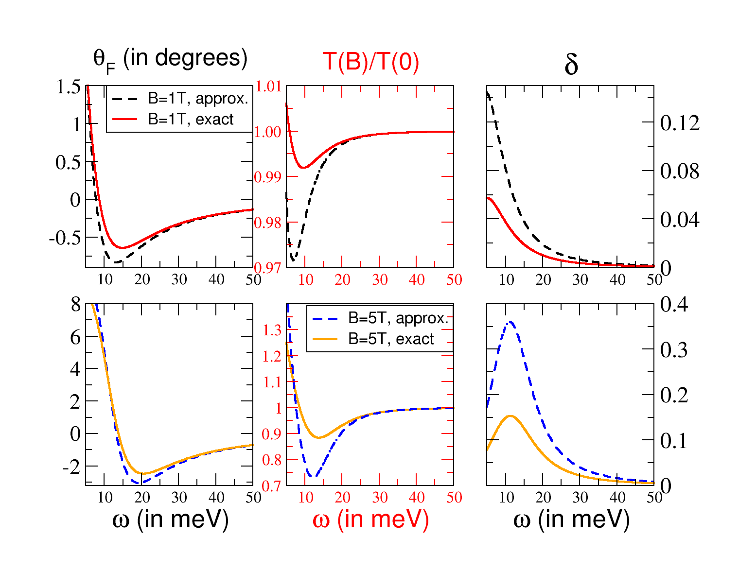
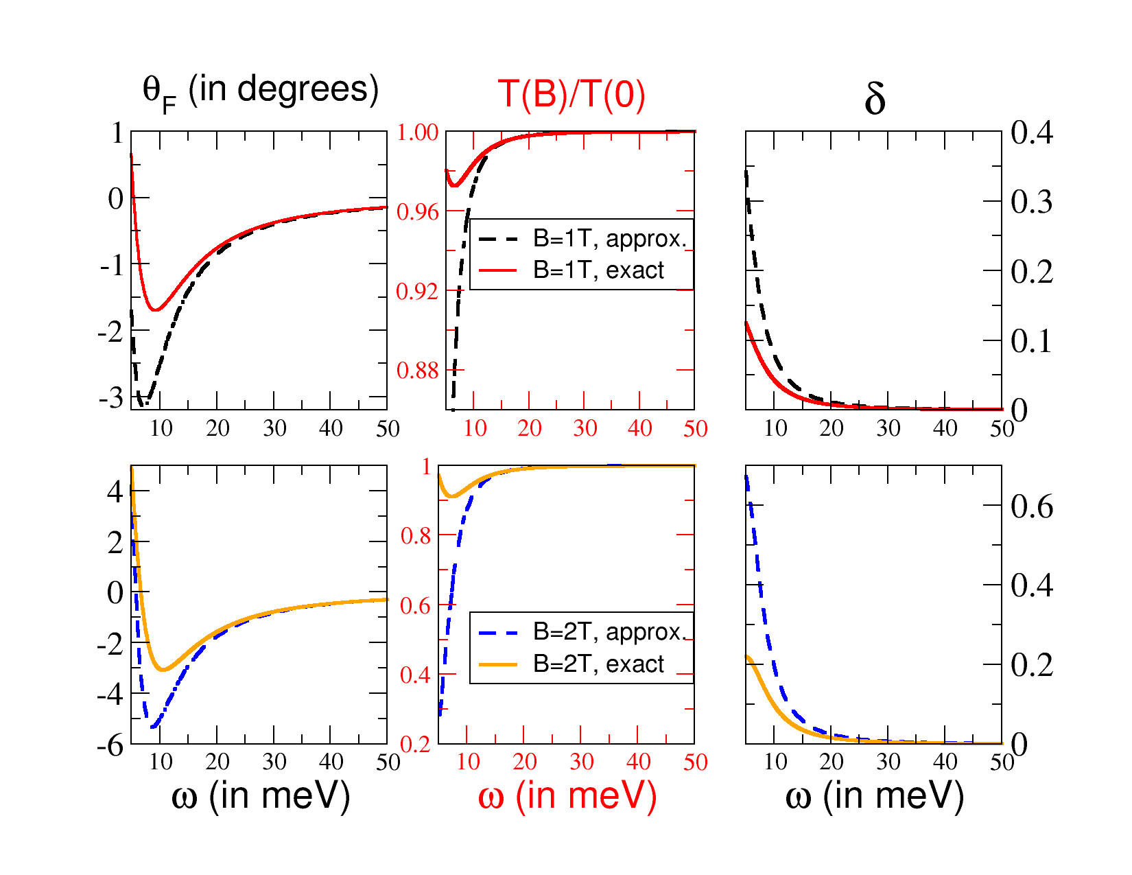
Refer to caption
Refer to caption
Figure 11: Faraday rotation angle (in degrees), normalized transmittance, and ellipticity of electromagnetic radiation passing through graphene subjected to a perpendicular magnetic field. The graphene sample is assumed to have a finite electronic density, EF=0.3subscript𝐸𝐹0.3E_{F}=0.3Β eV, and to be on top of SiO2 (Ο΅r=3.9subscriptitalic-Ο΅π‘Ÿ3.9\epsilon_{r}=3.9). Top six panels: Simulation of ΞΈFsubscriptπœƒπΉ\theta_{F}, T​(B)/T​(0)𝑇𝐡𝑇0T(B)/T(0), and δ𝛿\delta, considering a broadening of Ξ“=7Ξ“7\Gamma=7Β meV. Bottom six panels: Simulation of the same quantities as above for Ξ“=3.7Ξ“3.7\Gamma=3.7Β meV. In all panels, dashed lines correspond to approximate calculations, as given by Eqs.Β (94) and (96), and T=17𝑇17T=17Β K.

III.2 Fit to experimental data in the high-density regime

FigureΒ 12 shows fits for two sets of experimental data for ΞΈFsubscriptπœƒπΉ\theta_{F},FaradayNaturePhys measured when electromagnetic radiation passes through graphene epitaxially grown on silicon carbide (data taken at a temperature of 6Β K). According to the experiments by Crassee et al.,FaradayNaturePhys it was possible to produce a single graphene sheet grown on the Si-terminated surface of 6H-SiC (the sample underwent H passivation of the Si dangling bonds, resulting in quasi-free-standing single-layer graphene). Two sets of experimental data are shown in Fig.Β 12 (top), corresponding to two magnetic field intensities, B=7𝐡7B=7Β T and B=3𝐡3B=3Β T.

Refer to caption
Refer to caption
Figure 12: Faraday effect in doped graphene. Top: The Faraday rotation angle (in degrees) when graphene is grown on silicon carbide. Fit to the experimental values of ΞΈFsubscriptπœƒπΉ\theta_{F}, at a magnetic field of B=7𝐡7B=7Β T (left) and B=3𝐡3B=3Β T (right), using the semiclassical approach [dashed (green) line] and the full quantum calculation [solid (red) line]. Parameters are EF=0.3subscript𝐸𝐹0.3E_{F}=0.3Β eV, Ξ“=10.5Ξ“10.5\Gamma=10.5Β meV, T=6𝑇6T=6Β K, and Ο΅r=4.4subscriptitalic-Ο΅π‘Ÿ4.4\epsilon_{r}=4.4. Bottom: Theoretical optical conductivity [Eqs.Β (47) and (60)] for the same parameters used to fit the experimental data: B=7𝐡7B=7Β T (left) and B=3𝐡3B=3Β T (right).

In the course of the experiments it was found that the bare substrate did not reveal any Faraday effect, and therefore the measured rotation angle is intrinsic to graphene. This statement is confirmed by the model developed in Sec.Β III.1. ARPES measurements on the sample used indicated a Fermi energy of the order of EF≃0.34Β±0.01similar-to-or-equalssubscript𝐸𝐹plus-or-minus0.340.01E_{F}\simeq 0.34\pm 0.01Β eV.

In order to fit the data we have used EF=0.3subscript𝐸𝐹0.3E_{F}=0.3Β eV. We do not expect a perfect fit because we are considering a lossless dielectric. Nevertheless, the fit is fairly accurate, given the simplicity of the model. Moreover, the value of Ο΅rsubscriptitalic-Ο΅π‘Ÿ\epsilon_{r} was set to 4.4 which is not the relative permittivity of SiC and must be understood as an effective number, given that the experimental data were taken with epitaxially grown graphene. Although the calculation in Sec.Β II.4 does not include this fact explicitly, the fits are satisfactory, for they reproduce the main features of the experimental data: a decrease in ΞΈFsubscriptπœƒπΉ\theta_{F} with the photon energy until a minimum is reached for β„β€‹Ο‰β‰ˆ26Planck-constant-over-2-piπœ”26\hbar\omega\approx 26Β meVΒ (20Β meV) when the magnetic field intensity is 7Β TΒ (3Β T).

Comparing the top and bottom panels in Fig.Β 12, it can be seen that the minimum (maximum) of the Faraday rotation angle coincides roughly with the maximum (minimum) of Οƒx​yβ€²superscriptsubscript𝜎π‘₯𝑦′\sigma_{xy}^{\prime}. The latter fact agrees well with what could be concluded from the approximated result stated in Eq.Β (94). In order to interpret the variation of the Faraday rotation angle with the photon energy, it is sufficient to use the simplified results derived in Sec.Β II.4 for T=0𝑇0T=0, namely, Eqs.Β (62)-(68). (This is clearly justified given the low temperature in the experiment in Ref.Β FaradayNaturePhys, ; the respective thermal energy corresponds to about 0.010.010.01 times the level spacing Ξ”1=E1βˆ’E0subscriptΞ”1subscript𝐸1subscript𝐸0\Delta_{1}=E_{1}-E_{0} [see Eq.Β (50) for the definition of Ξ”nsubscriptΔ𝑛\Delta_{n}] for both intensities of magnetic field.)

For a magnetic field of 7Β TΒ (3Β T), intraband transitions n=9β†’n=10𝑛9→𝑛10n=9\rightarrow n=10 (n=22β†’n=23𝑛22→𝑛23n=22\rightarrow n=23) control the variation of ΞΈFsubscriptπœƒπΉ\theta_{F}, from positive up to negative values, as the photon energy varies. Here, the index n𝑛n denotes LLs with energy given by En=sign​(n)​2​|n|​ℏ​vF/lBsubscript𝐸𝑛sign𝑛2𝑛Planck-constant-over-2-pisubscript𝑣𝐹subscript𝑙𝐡E_{n}=\textrm{sign}(n)\sqrt{2|n|}\hbar v_{F}/l_{B} [see Eq.Β (5) and text thereafter]. The remaining transitions contributing to the Hall conductivity are interband-like and occur at much higher photon energies ℏ​ω≃2​EFsimilar-to-or-equalsPlanck-constant-over-2-piπœ”2subscript𝐸𝐹\hbar\omega\simeq 2E_{F}, and thus it does not influence the Faraday rotation in the range of energy plotted in Fig.Β 12.

In this example, intraband transitions involve a very small difference in energy, even when the magnetic field is 7Β T. The value of the intraband gap [Eq.Β (50)] is Ξ”NF≃16similar-to-or-equalssubscriptΞ”subscript𝑁𝐹16\Delta_{N_{F}}\simeq 16Β meV (Ξ”NF≃7similar-to-or-equalssubscriptΞ”subscript𝑁𝐹7\Delta_{N_{F}}\simeq 7Β meV) for B=7𝐡7B=7Β TΒ (B=3𝐡3B=3Β T), which is comparable to ΓΓ\Gamma (here NFsubscript𝑁𝐹N_{F} denotes the last occupied LL for a given Fermi energy). The exact calculation shows that the extrema points of the real part of the intraband Hall conductivity [Eq.Β (62)] occur at Ο‰=0πœ”0\omega=0, and,

ω±intrasuperscriptsubscriptπœ”plus-or-minusintra\displaystyle\omega_{\pm}^{\textrm{intra}} =1ℏ​Re​Δ+NF2Ξ“2Β±2ΓΔ+NF2Ξ“2.\displaystyle=\frac{1}{\hbar}\textrm{Re}\,\sqrt{\Delta{}_{N_{F}}^{2}+\Gamma^{2}\pm 2\Gamma\sqrt{\Delta{}_{N_{F}}^{2}+\Gamma^{2}}}\,. (97)

Substituting the values given in the caption to Fig.Β 12 into the latter formula, we obtain Ο‰+intra≃27similar-to-or-equalssuperscriptsubscriptπœ”intra27\omega_{+}^{\textrm{intra}}\simeq 27Β meV (Ο‰+intra≃20similar-to-or-equalssuperscriptsubscriptπœ”intra20\omega_{+}^{\textrm{intra}}\simeq 20Β meV) for a field intensity of 7Β TΒ (3Β T). As mentioned above, these are the points where the Faraday rotation reaches its minimum value. Increasing further the photon energy, ℏ​ω>ℏ​ω+intraPlanck-constant-over-2-piπœ”Planck-constant-over-2-pisuperscriptsubscriptπœ”intra\hbar\omega>\hbar\omega_{+}^{\textrm{intra}}, the Faraday rotation increases toward zero, essentially because at large Ο‰πœ”\omega, below the interband threshold, the Hall conductivity becomes very low (Fig.Β 12) and no distinction arises between Οƒβˆ’subscript𝜎\sigma_{-} and Οƒ+subscript𝜎\sigma_{+}, and thus t+β‰ˆtβˆ’subscript𝑑subscript𝑑t_{+}\approx t_{-}. Increasing the photon energy up to β„β€‹Ο‰βˆΌ2​EFsimilar-toPlanck-constant-over-2-piπœ”2subscript𝐸𝐹\hbar\omega\sim 2E_{F}, the interband transition comes into play and drives the Faraday rotation. Interband transitions are important in samples with low electronic densities, as explained in the following section.

The curves for ΞΈFsubscriptπœƒπΉ\theta_{F}, computed either from the semiclassical expressions for the conductivity [Eqs.Β (78) and (79)] or via the EOM expressions [Eqs.Β (47) and (60)] are almost indistinguishable (see Fig.Β 12, top), in the range of photon energies considered, except for β„β€‹Ο‰β‰ˆ10Planck-constant-over-2-piπœ”10\hbar\omega\approx 10Β meV, where a very small deviation is observed when the intensity of the magnetic field is 7Β T.

The agreement between the quantum and the semiclassical solutions is explained by the similarity of the intraband gap Ξ”NFsubscriptΞ”subscript𝑁𝐹\Delta_{N_{F}} and the cyclotron energy ℏ​ωcPlanck-constant-over-2-pisubscriptπœ”π‘\hbar\omega_{c} [see Eq.Β (76)]. The values for these quantities are Ξ”NF≃6.62similar-to-or-equalssubscriptΞ”subscript𝑁𝐹6.62\Delta_{N_{F}}\simeq 6.62(15.615.615.6)Β meV and ℏ​ωc≃6.58similar-to-or-equalsPlanck-constant-over-2-pisubscriptπœ”π‘6.58\hbar\omega_{c}\simeq 6.58(15.415.415.4)Β meV for a field of 333(777)Β T. The agreement between the methods breaks down near the interband threshold, ℏ​ω≃2​EF≃0.6similar-to-or-equalsPlanck-constant-over-2-piπœ”2subscript𝐸𝐹similar-to-or-equals0.6\hbar\omega\simeq 2E_{F}\simeq 0.6Β eV, where the quantum contribution arising from the interband transition cannot be neglected.
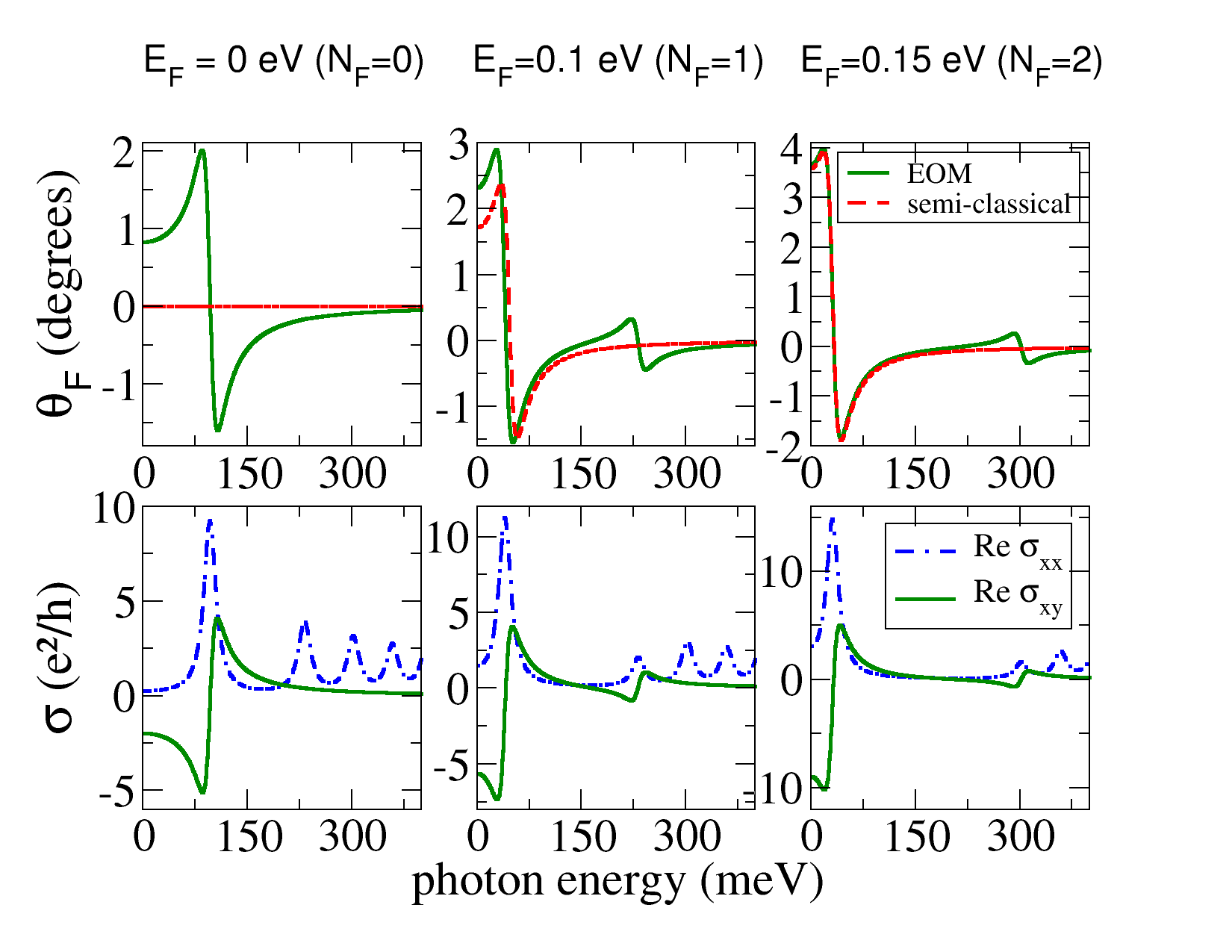
Refer to caption
Figure 13: Low electronic density limit. Top: Faraday rotation angle (given in degrees) for free-standing graphene (Ο΅r=1subscriptitalic-Ο΅π‘Ÿ1\epsilon_{r}=1) for different LL occupations: from left to right, NF=0,1,subscript𝑁𝐹01N_{F}=0,1, and 2. The magnetic field intensity is B=7𝐡7B=7Β T, Ξ“=10.5Ξ“10.5\Gamma=10.5Β meV and T=0𝑇0T=0. Adding a dielectric substrate to graphene decreases the maximum amount of Faraday rotation that is achievable, without introducing major qualitative changes [see Eq.Β (94)]. Bottom: Real part of the quantum conductivity tensor for the Fermi energies considered in the top panel.

III.3 Quantum jumps in the Faraday rotation: the low electronic density limit

When low Fermi energies are considered, energy quantization becomes important (see Secs.Β II.4 and II.5). The limiting case occurs for 0≀EF<2​ℏ​vF/lB0subscript𝐸𝐹2Planck-constant-over-2-pisubscript𝑣𝐹subscript𝑙𝐡0\leq E_{F}<\sqrt{2}\hbar v_{F}/l_{B}, i.e.,Β NF=0subscript𝑁𝐹0N_{F}=0. In this case, at T=0𝑇0T=0, LLs with nβ‰₯1𝑛1n\geq 1 are all empty, and a single type of transition contributes to the Hall conductivity, n=0β†’n=1𝑛0→𝑛1n=0\rightarrow n=1. Since this transition is interband-like, it cannot be explained within the semiclassical treatment (Secs.Β II.4 and II.5). This situation is illustrated in Fig.Β 13 (bottom): when NF=0subscript𝑁𝐹0N_{F}=0, the real part of the Hall conductivity [solid (green) line] has a finite (nonzero) value around ω≃(E1+E0)/ℏsimilar-to-or-equalsπœ”subscript𝐸1subscript𝐸0Planck-constant-over-2-pi\omega\simeq(E_{1}+E_{0})/\hbar. [Note that the extrema of the interband Hall conductivity can be obtained from Eq.Β (97) by making the replacement Ξ”NF→ℏ​Δ​ΩNFβ†’subscriptΞ”subscript𝑁𝐹Planck-constant-over-2-piΞ”subscriptΞ©subscript𝑁𝐹\Delta_{N_{F}}\rightarrow\hbar\Delta\Omega_{N_{F}}, with Δ​ΩNFΞ”subscriptΞ©subscript𝑁𝐹\Delta\Omega_{N_{F}} given by Eq.Β (53).] The Faraday rotation given by the semiclassical model is obviously 0 [dashed (red) line] since EF=0subscript𝐸𝐹0E_{F}=0 [Eq.Β (79)]. The respective Faraday rotation angle (top) is approximately proportional to βˆ’Οƒx​y​(Ο‰)subscript𝜎π‘₯π‘¦πœ”-\sigma_{xy}(\omega).

At higher Fermi energies (i.e., NF>0subscript𝑁𝐹0N_{F}>0), two types of transitions contribute to the Hall conductivity: in general, for ENF<EF<ENF+1subscript𝐸subscript𝑁𝐹subscript𝐸𝐹subscript𝐸subscript𝑁𝐹1E_{N_{F}}<E_{F}<E_{N_{F}+1}, with NFβ‰₯1subscript𝑁𝐹1N_{F}\geq 1, the allowed transitions are (i) interband between the hole’s LLs with n=βˆ’NF𝑛subscript𝑁𝐹n=-N_{F} and the electron’s LLs with n=NF+1𝑛subscript𝑁𝐹1n=N_{F}+1 and (ii) intraband between LLs with n=NF𝑛subscript𝑁𝐹n=N_{F} and n=NF+1𝑛subscript𝑁𝐹1n=N_{F}+1 (Sec.Β II.4). The maximum intensity of Οƒx​yβ€²superscriptsubscript𝜎π‘₯𝑦′\sigma_{xy}^{\prime} falls off with the inverse of the energy difference associated with a given electronic transition [Eqs.Β (67) and (68)]. Since, up to a good degree of approximation, the Faraday effect is controlled by Οƒx​yβ€²superscriptsubscript𝜎π‘₯𝑦′\sigma_{xy}^{\prime}, the latter means that the amount of Faraday rotation induced by the interband transitions at Ο‰=Δ​ΩNFπœ”Ξ”subscriptΞ©subscript𝑁𝐹\omega=\Delta\Omega_{N_{F}} will be smaller than the Faraday rotation due to intraband processes.

The above-mentioned facts can be appreciated in Fig.Β 13, where numerical data for ΞΈFsubscriptπœƒπΉ\theta_{F} (top), Οƒx​xβ€²superscriptsubscript𝜎π‘₯π‘₯β€²\sigma_{xx}^{\prime} and Οƒx​yβ€²superscriptsubscript𝜎π‘₯𝑦′\sigma_{xy}^{\prime} (bottom) are shown with Fermi energy increasing from left to right. As higher LLs in the conduction band become occupied, the spectral weight for the interband contribution to Οƒx​yβ€²superscriptsubscript𝜎π‘₯𝑦′\sigma_{xy}^{\prime} shifts toward higher energies (that is, ℏ​Δ​ΩNFPlanck-constant-over-2-piΞ”subscriptΞ©subscript𝑁𝐹\hbar\Delta\Omega_{N_{F}} increases β†’β†’\rightarrow ω±intersuperscriptsubscriptπœ”plus-or-minusinter\omega_{\pm}^{\textrm{inter}} increases). The opposite occurs for intraband transitions, since in this case, the relevant energy scale Ξ”NFsubscriptΞ”subscript𝑁𝐹\Delta_{N_{F}} decreases with increasing EFsubscript𝐸𝐹E_{F}. As a result, the intraband part of Οƒx​yβ€²superscriptsubscript𝜎π‘₯𝑦′\sigma_{xy}^{\prime} concentrates its spectral weight at the lower edge of the plotted spectrum, and displays a much higher amplitude than its interband counterpart, as explained above. Similar conclusions apply to ΞΈFsubscriptπœƒπΉ\theta_{F}, as direct inspection of the bottom and top panels shows.
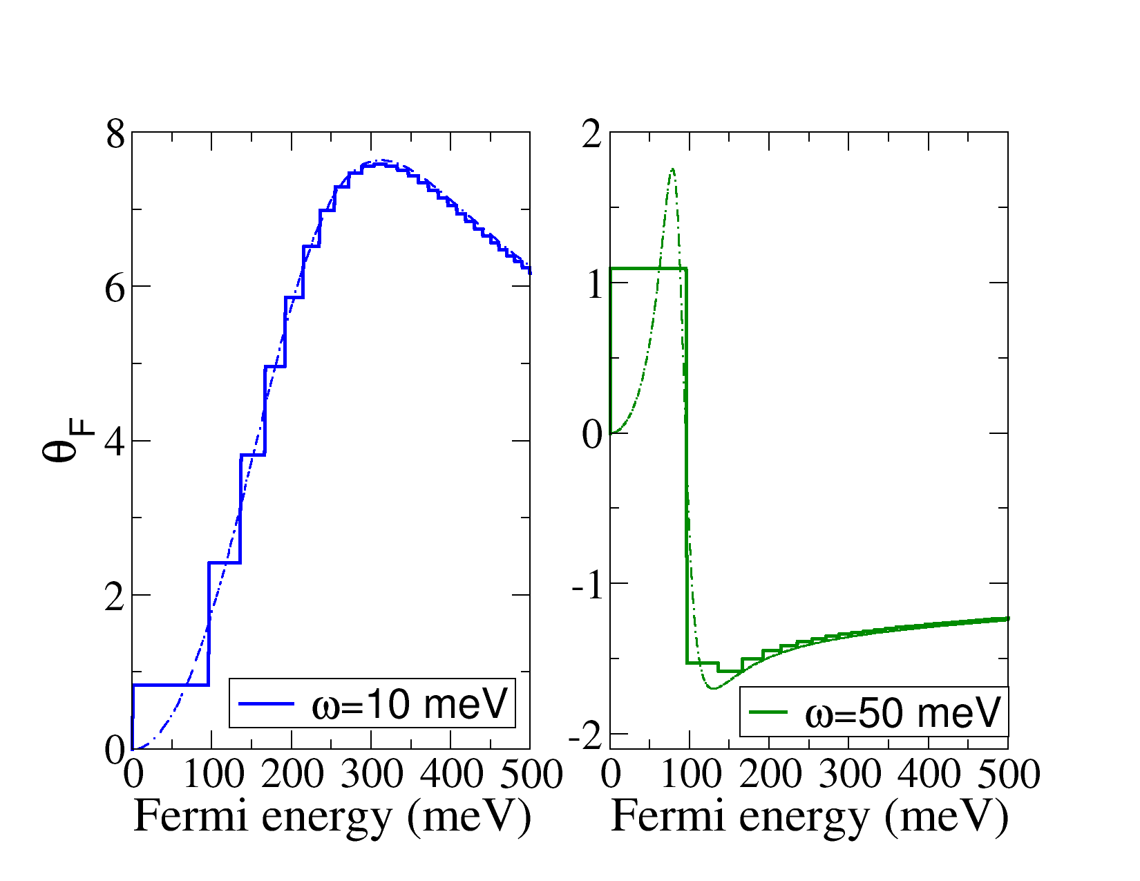
Refer to caption
Refer to caption
Figure 14: Quantization of the Faraday effect in graphene. Top: Faraday rotation angle (in degrees) for free-standing graphene as a function of the Fermi energy at a magnetic field of B=7𝐡7B=7Β T for ℏ​ω=10Planck-constant-over-2-piπœ”10\hbar\omega=10Β meV (left) and ℏ​ω=50Planck-constant-over-2-piπœ”50\hbar\omega=50Β meV (right). The respective semi-classical result is plotted by the dashed lines. Other parameters: Ξ“=10.5Ξ“10.5\Gamma=10.5Β meV and T=12𝑇12T=12Β K. Bottom: Same as the top panel but with Ξ“=2Ξ“2\Gamma=2Β meV.

When NF=1subscript𝑁𝐹1N_{F}=1, a significant departure from the semiclassical behavior can be appreciated in the intraband region (0βˆ’10001000-100Β meV). Remarkably, though, already for NF=2subscript𝑁𝐹2N_{F}=2, the semiclassical Hall conductivity approximates the quantum result well, with a significant deviation occurring only near the interband threshold (β‰ˆ\approx300Β meV), where the semiclassical approach must necessarily fail. These features are in accordance with the general conclusions drawn in Sec.Β II.4.

For comparison, the real part of the longitudinal conductivity is also shown in the bottom panel in Fig.Β 13. The longitudinal current can be induced by photons which are resonant with any interband transition allowed by the Pauli principle (i.e., ℏ​ω>ℏ​Δ​ΩNF≃2​EFPlanck-constant-over-2-piπœ”Planck-constant-over-2-piΞ”subscriptΞ©subscript𝑁𝐹similar-to-or-equals2subscript𝐸𝐹\hbar\omega>\hbar\Delta\Omega_{N_{F}}\simeq 2E_{F}), and hence many absorption peaks can be observed. On the contrary, the Faraday rotation essentially depends on Οƒx​yβ€²superscriptsubscript𝜎π‘₯𝑦′\sigma_{xy}^{\prime} and therefore is driven only by two resonances.

Dependence on the Fermi energy and magnetic fieldβ€”We have seen that when few LLs are occupied, quantum effects come into play and the semiclassical solution no longer gives an accurate description of the Faraday effect. The latter can even happen in the intraband region (see, e.g., Fig.Β 13, middle panel), embodying the departure of the intraband gap Ξ”NFsubscriptΞ”subscript𝑁𝐹\Delta_{N_{F}} from its semiclassical analog, the cyclotron energy, ℏ​ωcPlanck-constant-over-2-pisubscriptπœ”π‘\hbar\omega_{c} (see TableΒ 1). Given the importance of energy quantization for a low electronic density, we expect ΞΈFsubscriptπœƒπΉ\theta_{F} to display abrupt behavior when the Fermi energy crosses the first few LLs. The latter behavior should reflect directly the step structure of the optical (or ac-) Hall conductivity Οƒx​y′​(Ο‰)superscriptsubscript𝜎π‘₯π‘¦β€²πœ”\sigma_{xy}^{\prime}(\omega).Morimoto2009

Figure 14 shows the Faraday rotation angle versus EFsubscript𝐸𝐹E_{F} for a fixed magnetic field, B=7𝐡7B=7 T. The heights of the steps are not uniform since the optical Hall conductivity no longer obeys the dc quantization rule [Eq. (69)]. When the Fermi energy crosses higher LLs, the smooth semiclassical result (dashed curves) is recovered.

Combining the approximated formula for ΞΈFsubscriptπœƒπΉ\theta_{F} [Eq.Β (94); valid for cβ€‹ΞΌβ€‹Οƒβˆ“β€²β€‹(Ο‰)β‰ͺ2much-less-thanπ‘πœ‡superscriptsubscript𝜎minus-or-plusβ€²πœ”2c\mu\sigma_{\mp}^{\prime}(\omega)\ll 2 and ΞΈF≲1less-than-or-similar-tosubscriptπœƒπΉ1\theta_{F}\lesssim 1] and the exact Hall conductivity at T=0𝑇0T=0 [Eqs.Β (62) and (63)], explicit formulas for the step heights can be obtained. When the Fermi energy crosses LLs with n>1𝑛1n>1, the expression for Δ​θFΞ”subscriptπœƒπΉ\Delta\theta_{F} becomes somewhat cumbersome. Nevertheless, simple analytical expressions can be obtained in some regimes. For instance, when the photon energy is small compared to relevant scales, ℏ​ωβ‰ͺΞ“β‰ͺE1much-less-thanPlanck-constant-over-2-piπœ”Ξ“much-less-thansubscript𝐸1\hbar\omega\ll\Gamma\ll E_{1}, the steps are predicted to be approximately uniform,

Δ​θF(nβ†’n+1)≃2​c​μ​e2h=4​α≃0.03​rad,similar-to-or-equalsΞ”superscriptsubscriptπœƒπΉβ†’π‘›π‘›12π‘πœ‡superscript𝑒2β„Ž4𝛼similar-to-or-equals0.03rad\Delta\theta_{F}^{(n\rightarrow n+1)}\simeq\frac{2c\mu e^{2}}{h}=4\alpha\simeq 0.03\,\textrm{rad}, (98)

where α𝛼\alpha denotes the fine structure constant, Ξ±=e2/(4​π​ℏ​ϡ0​c)𝛼superscript𝑒24πœ‹Planck-constant-over-2-pisubscriptitalic-Ο΅0𝑐\alpha=e^{2}/(4\pi\hbar\epsilon_{0}c). In Ref.Β [Morimoto2009, ], for estimation of the magnitude of the effect it was assumed that the step height of Οƒx​yβ€²superscriptsubscript𝜎π‘₯𝑦′\sigma_{xy}^{\prime} is approximately given by Δ​σx​y′​(Ο‰)≃e2/hsimilar-to-or-equalsΞ”superscriptsubscript𝜎π‘₯π‘¦β€²πœ”superscript𝑒2β„Ž\Delta\sigma_{xy}^{\prime}(\omega)\simeq e^{2}/h, resulting in Δ​θF≃αsimilar-to-or-equalsΞ”subscriptπœƒπΉπ›Ό\Delta\theta_{F}\simeq\alpha. Rigorously, the step height for the transitions n=0β†’n=1𝑛0→𝑛1n=0\rightarrow n=1 is about 4​e2/h4superscript𝑒2β„Ž4e^{2}/h, hence explaining the extra factor of 4 in our expression. In fact, in the limit ℏ​ωβ‰ͺΞ“β‰ͺE1much-less-thanPlanck-constant-over-2-piπœ”Ξ“much-less-thansubscript𝐸1\hbar\omega\ll\Gamma\ll E_{1}, the steps in the Hall conductivity will all have approximately the same height, as in the dc case [see Eq.Β (69)].

In Fig.Β 14, a decrease in the step’s height relative to the estimated value in Eq.Β (98) can be observed already for the first step. This happens because the condition Ξ“β‰ͺE1much-less-thanΞ“subscript𝐸1\Gamma\ll E_{1} is too restrictive, and hence we relax this condition to Γ≲E1less-than-or-similar-toΞ“subscript𝐸1\Gamma\lesssim E_{1}, but, at the same time, keep the low-photon-energy condition, ℏ​ωβ‰ͺΞ“much-less-thanPlanck-constant-over-2-piπœ”Ξ“\hbar\omega\ll\Gamma. Doing so, leads to a better approximation,

Δ​θF(nβ†’n+1)≃11+(6+4​n+Ξ΄n,0)​γ~2​11+4​n​γ~2Γ—4​α,similar-to-or-equalsΞ”superscriptsubscriptπœƒπΉβ†’π‘›π‘›11164𝑛subscript𝛿𝑛0superscript~𝛾2114𝑛superscript~𝛾24𝛼\Delta\theta_{F}^{(n\rightarrow n+1)}\simeq\frac{1}{1+(6+4n+\delta_{n,0})\tilde{\gamma}^{2}}\frac{1}{1+4n\tilde{\gamma}^{2}}\times 4\alpha\,, (99)

where we have defined the dimensionless parameter Ξ³~=Ξ“/E1~𝛾Γsubscript𝐸1\tilde{\gamma}=\Gamma/E_{1}. Using this parameter, the validity condition of Eq.Β (99) reads, Ξ³~≲1less-than-or-similar-to~𝛾1\tilde{\gamma}\lesssim 1 and ℏ​ωβ‰ͺΞ“much-less-thanPlanck-constant-over-2-piπœ”Ξ“\hbar\omega\ll\Gamma.

Two physical scenarios where the Faraday steps are not uniform are shown in Fig.Β 14. In the bottom panel, the transitions n=0β†’n=1𝑛0→𝑛1n=0\rightarrow n=1 (EF≃100similar-to-or-equalssubscript𝐸𝐹100E_{F}\simeq 100Β meV) come with a variation of ΞΈFsubscriptπœƒπΉ\theta_{F} of roughly 1.8∘superscript1.81.8^{\circ} (≃0.031similar-to-or-equalsabsent0.031\simeq 0.031Β rad) for ℏ​ω=10Planck-constant-over-2-piπœ”10\hbar\omega=10Β meV, versus βˆ’5.1∘superscript5.1-5.1^{\circ} (β‰ƒβˆ’0.089similar-to-or-equalsabsent0.089\simeq-0.089Β rad) for ℏ​ω=Planck-constant-over-2-piπœ”absent\hbar\omega=50Β meV, which does not agree either with the rough uniform estimative or with Eq.Β (99). The reason for this discrepancy is that the condition ℏ​ωβ‰ͺΞ“much-less-thanPlanck-constant-over-2-piπœ”Ξ“\hbar\omega\ll\Gamma is not fulfilled for the photon frequencies considered in Fig.Β 14. Recall that in graphene, ΓΓ\Gamma is about about 10 meV, and thus infrared photons have ℏ​ω≳Γgreater-than-or-equivalent-toPlanck-constant-over-2-piπœ”Ξ“\hbar\omega\gtrsim\Gamma. It is therefore useful to derive approximate formulas for Δ​θFΞ”subscriptπœƒπΉ\Delta\theta_{F} that are valid in the regime ℏ​ω≫Γmuch-greater-thanPlanck-constant-over-2-piπœ”Ξ“\hbar\omega\gg\Gamma. Defining Ο‰~=E1/(ℏ​ω)~πœ”subscript𝐸1Planck-constant-over-2-piπœ”\tilde{\omega}=E_{1}/(\hbar\omega), we arrive at

Δ​θF(nβ†’n+1)≃4​α1βˆ’2​(1+2​n)​ω~2+Ο‰~4​1βˆ’Ο‰~41βˆ’2​(3+2​n)​ω~2+Ο‰~4.similar-to-or-equalsΞ”superscriptsubscriptπœƒπΉβ†’π‘›π‘›14𝛼1212𝑛superscript~πœ”2superscript~πœ”41superscript~πœ”41232𝑛superscript~πœ”2superscript~πœ”4\Delta\theta_{F}^{(n\rightarrow n+1)}\simeq\frac{4\alpha}{1-2(1+2n)\tilde{\omega}^{2}+\tilde{\omega}^{4}}\frac{1-\tilde{\omega}^{4}}{1-2(3+2n)\tilde{\omega}^{2}+\tilde{\omega}^{4}}\,. (100)

Substituting for the respective values of Ο‰~~πœ”\tilde{\omega}, we obtain Δ​θF(0β†’1)=1.8βˆ˜Ξ”superscriptsubscriptπœƒπΉβ†’01superscript1.8\Delta\theta_{F}^{(0\rightarrow 1)}=1.8^{\circ} and Δ​θF(0β†’1)=βˆ’5.3βˆ˜Ξ”superscriptsubscriptπœƒπΉβ†’01superscript5.3\Delta\theta_{F}^{(0\rightarrow 1)}=-5.3^{\circ}, for ℏ​ω=10Planck-constant-over-2-piπœ”10\hbar\omega=10Β eV and ℏ​ω=50Planck-constant-over-2-piπœ”50\hbar\omega=50Β meV, respectively, which agrees well with the numerical results reported in Fig.Β 14 for Ξ“=2Ξ“2\Gamma=2Β meV. As for the steps observed in the top panel in Fig.Β 14, they cannot be explained accurately with Eq.Β (100) since in that case we have β„β€‹Ο‰β‰ˆπ’ͺ​(Ξ“)Planck-constant-over-2-piπœ”π’ͺΞ“\hbar\omega\approx\mathcal{O}(\Gamma). We stress that Eqs.Β (99) and (100) are only accurate when the statement, Eq.Β (94), provides a good description of the Faraday effect in graphene, which in practice means very high photon energies ℏ​ωPlanck-constant-over-2-piπœ”\hbar\omega (see also Fig.Β 11). For the parameters used in Fig.Β 14, where the photon energies are not very high, our analytical expressions for Δ​θFΞ”subscriptπœƒπΉ\Delta\theta_{F} are accurate only for the first few steps.

FigureΒ 15 shows the variation of ΞΈFsubscriptπœƒπΉ\theta_{F} with the magnetic field for two cases; (i) low doping (EF=0.05subscript𝐸𝐹0.05E_{F}=0.05Β eV) and (ii) high doping (EF=0.3subscript𝐸𝐹0.3E_{F}=0.3Β eV). In the latter case, we are well inside the semiclassical regime even for the maximum intensity of the magnetic field considered (B=𝐡absentB=7Β T), and thus no distinction can be made between the curves computed using the semiclassical conductivity tensor or the EOM formulas. In this regime, the Faraday effect increases monotonously with the magnetic field.

For a low electronic density, on the other hand, the agreement between the Boltzmann and the EOM formalisms takes place only for low magnetic fields. For increasing values of the magnetic fields, such agreement ceases to occur as soon as the intraband gap does not match the cyclotron energy ℏ​ωcPlanck-constant-over-2-pisubscriptπœ”π‘\hbar\omega_{c}. Then, energy level quantization becomes important and the EOM expressions must be considered (i.e., NFsubscript𝑁𝐹N_{F} is small; see Sec.Β II.5): this explains the departure from the semiclassical value for ΞΈFsubscriptπœƒπΉ\theta_{F} observed in the right panel in Bβ‰ˆ1𝐡1B\thickapprox 1Β T for ℏ​ω=10Planck-constant-over-2-piπœ”10\hbar\omega=10Β meV (Bβ‰ˆ0.5𝐡0.5B\thickapprox 0.5Β T for ℏ​ω=30Planck-constant-over-2-piπœ”30\hbar\omega=30Β meV). If the magnetic field intensity is higher than a given value, we necessarily have NF=0subscript𝑁𝐹0N_{F}=0 (for 0.05Β eV this value is about 1.9Β T). In this case, the Hall conductivity, at T=0𝑇0T=0, is fully determined by a single type of interband transition, and, assuming E1​(B)≫ℏ​ω,Ξ“much-greater-thansubscript𝐸1𝐡Planck-constant-over-2-piπœ”Ξ“E_{1}(B)\gg\hbar\omega,\Gamma, we obtain [see Eq.Β (63)],

Οƒx​y′≃large ​Bβˆ’2​e2hβ‡’ΞΈF≃2α≃3Γ—10βˆ’4.∘\sigma_{xy}^{\prime}\underset{\textrm{large }B}{\simeq}-\frac{2e^{2}}{h}\Rightarrow\theta_{F}\simeq 2\alpha\simeq 3\times 10^{-4}\,{}^{\circ}\>. (101)

The latter considerations explain the plateau formed at Bβ‰ˆ2𝐡2B\thickapprox 2Β T [solid (blue) line] in the right panel in Fig.Β 15. The dashed-double-dotted (red) line corresponds to photons with a higher energy, shifting the formation of the plateau toward higher fields. EquationΒ (101) is indeed the high-magnetic-field limit [E1​(B)≫much-greater-thansubscript𝐸1𝐡absentE_{1}(B)\ggΒ energy scales] of the Faraday rotation induced by single-layer graphene.
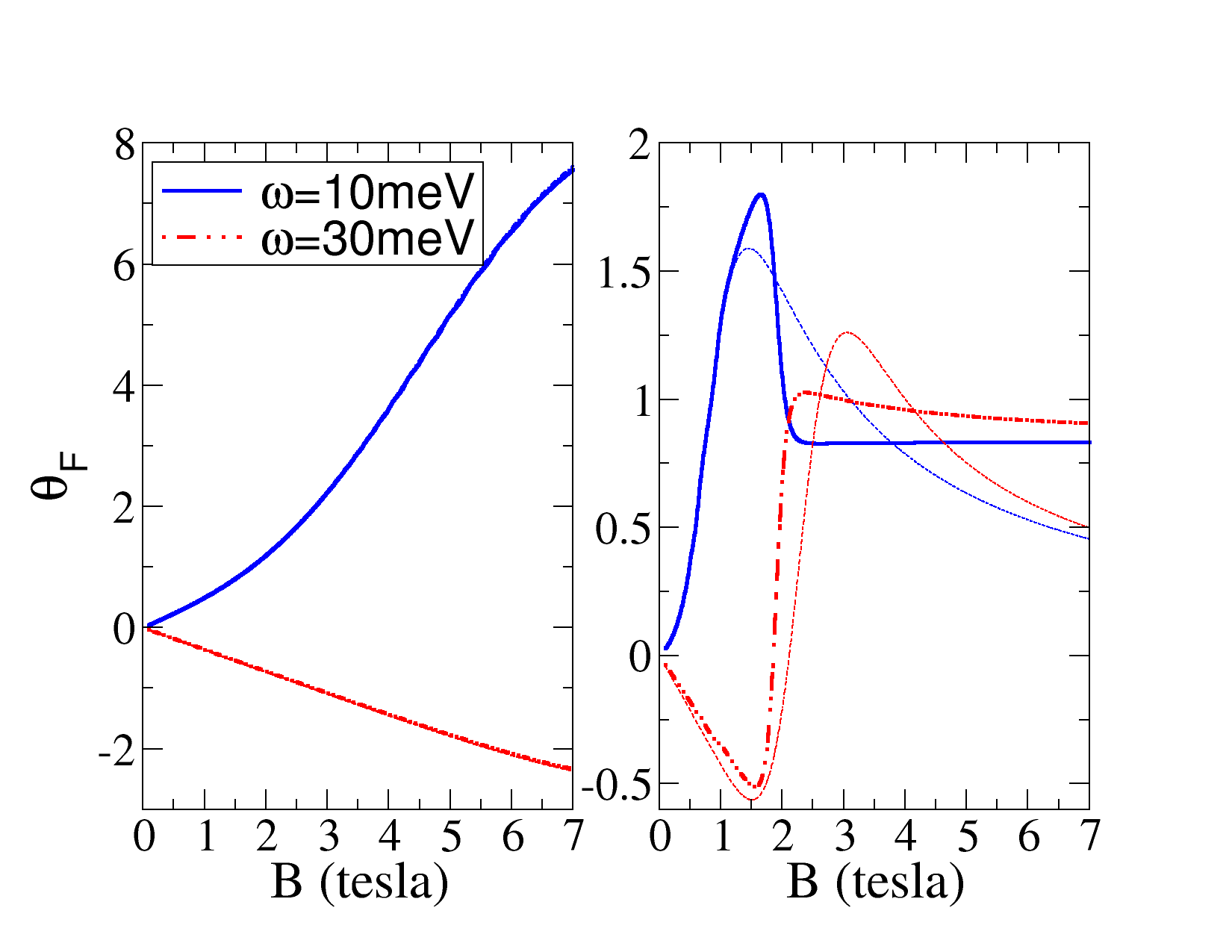
Refer to caption
Figure 15: Faraday rotation angle (in degrees) as a function of the magnetic field for EF=0.30subscript𝐸𝐹0.30E_{F}=0.30Β eV (left) and EF=0.05subscript𝐸𝐹0.05E_{F}=0.05Β eV (right). In each panel two photon energies are represented—ℏ​ω=10Planck-constant-over-2-piπœ”10\hbar\omega=10Β meV [solid (blue) line] and ℏ​ω=30Planck-constant-over-2-piπœ”30\hbar\omega=30Β meV [dashed-double-dotted (red) line]β€”with the respective semiclassical counterparts shown by dashed lines. Other parameters as in the top panel in Fig.Β 14.

Although the measured Faraday rotation angle is remarkably large given that it comes from a single graphene layer, in both low and high doping regimes (see Fig.Β 15), it is the needed magnetic field, B≳1greater-than-or-equivalent-to𝐡1B\gtrsim 1Β T. The goal is then to obtain large Faraday rotation angles using graphene and modest fields at the same time. A simple idea that uses the nonreciprocity of the Faraday effect is to enclose graphene between two mirrors. We discuss this possibility in the following section.

III.4 Enhancement of Faraday rotation in a cavity geometry

We have seen that the existence of intraband and interband transitions in graphene permits the generation of finite (nonzero) Faraday rotations in different ranges of the electromagnetic spectrum. In doped graphene (NFβ‰₯1subscript𝑁𝐹1N_{F}\geq 1), e.g., the intraband gap is bounded from above by

Eintra≀Δ1=E2βˆ’E1≃15​B​meVβ‹…Tβˆ’1/2,superscript𝐸intrasubscriptΞ”1subscript𝐸2subscript𝐸1similar-to-or-equalsβ‹…15𝐡meVsuperscriptT12E^{\textrm{intra}}\leq\Delta_{1}=E_{2}-E_{1}\simeq 15\sqrt{B}\,\textrm{meV}\cdot\textrm{T}^{-1/2}\,, (102)

implying that, by using magnetic field intensities ∼1similar-toabsent1\sim 1Β T, graphene can be exploited for magneto-optical applications from the microwave up to the far-infrared regimes f=E/h≲3.6π‘“πΈβ„Žless-than-or-similar-to3.6f=E/h\lesssim 3.6Β THz (an example of terahertz Faraday rotation driven by intraband transitions is given in Fig.Β 12). Another possibility is to make use of transitions connecting the valence and conduction Dirac cones, whose interband gaps are bounded from below,

Einterβ‰₯ℏ​Δ​Ω1=E1≃36​B​meVβ‹…Tβˆ’1/2,superscript𝐸interPlanck-constant-over-2-piΞ”subscriptΞ©1subscript𝐸1similar-to-or-equalsβ‹…36𝐡meVsuperscriptT12E^{\textrm{inter}}\geq\hbar\Delta\Omega_{1}=E_{1}\simeq 36\sqrt{B}\,\textrm{meV}\cdot\textrm{T}^{-1/2}\,, (103)

thus obtaining far-infrared up to visible light light frequencies (an example of mid-infrared Faraday rotation driven by interband transitions is shown in Fig.Β 13). We recall that increasing the electronic density in order to obtain even larger interband gaps (ℏ​Δ​ΩnPlanck-constant-over-2-piΞ”subscriptΩ𝑛\hbar\Delta\Omega_{n} with n>1𝑛1n>1), and thus shifting the magneto-optical response of graphene above the midinfrared, β„β€‹Ο‰βˆΌβ„β€‹Ξ”β€‹Ξ©NF≃2​EFsimilar-toPlanck-constant-over-2-piπœ”Planck-constant-over-2-piΞ”subscriptΞ©subscript𝑁𝐹similar-to-or-equals2subscript𝐸𝐹\hbar\omega\sim\hbar\Delta\Omega_{N_{F}}\simeq 2E_{F}, creates optical Hall conductivity peaks with a low intensity. As a consequence, very small Faraday rotations are produced already in the near-infrared regime. A good estimate for the maximum achievable interband-induced Faraday rotation can be obtained from Eqs.Β (68) and (94),

max​|ΞΈF|≃(e​B​vF22​ω​Γ)Γ—Ξ±,similar-to-or-equalsmaxsubscriptπœƒπΉπ‘’π΅superscriptsubscript𝑣𝐹22πœ”Ξ“π›Ό\textrm{max}\,|\theta_{F}|\simeq\left(\frac{eBv_{F}^{2}}{2\omega\Gamma}\right)\times\alpha\,, (104)

which, for example, taking B=7𝐡7B=7Β T , Ξ“=10Ξ“10\Gamma=10Β meV, and ℏ​ω=1Planck-constant-over-2-piπœ”1\hbar\omega=1Β eV, leads to max​|ΞΈF|≃10βˆ’3similar-to-or-equalsmaxsubscriptπœƒπΉsuperscript103\textrm{max}\,|\theta_{F}|\simeq 10^{-3}. Although the amounts of terahertz Faraday rotation, ℏ​ω≃O​meVsimilar-to-or-equalsPlanck-constant-over-2-piπœ”π‘‚meV\hbar\omega\simeq O\,\textrm{meV}, reported in our figures are well within state-of-the-art capabilities [the resolution for Faraday measurements in terahertz time-domain spectroscopy is presently limited to 1Β mradShimano2008 (∼similar-to\sim0.06Β degrees)], high magnetic fields, ∼1similar-toabsent1\sim 1Β T, are still needed which can be a disadvantage for specific applications; moreover, according to Eq.Β (104) the needed magnetic field increases as higher photon frequencies are to be probed.

The situation is very different in other 2D electron gases, for which ΞΈFsubscriptπœƒπΉ\theta_{F} is proportional to the sample’s thickness (as the light travels farther through the material, more Faraday rotation accumulates). Single-layer graphene, on the other hand, being one atom thick and hence truly 2D, requires the use of high magnetic fields in order to detect Faraday rotations. It is therefore natural to ask whether it is possible to conceive a setup leading to accumulation of Faraday effect; ideally, such setup would avoid the use of several samples and, at the same time, take advantage of the broad magneto-optical response of single-layer graphene.

In what follows, we discuss a graphene-based system that can enhance the intrinsic graphene’s Faraday rotation at any frequency and thus can cope with the difficulty mentioned above. The idea consists in enclosing graphene in an optical cavity: due to intracavity interference, photons undergo several round trips within the cavity before leaking out. Loosely speaking, due to nonreciprocity of the Faraday effect, accumulation of ΞΈFsubscriptπœƒπΉ\theta_{F} then takes place each time a photon passes through graphene; a sketch of the experimental apparatus is shown in Fig.Β 16.

Explicit calculations (see below) show that giant Faraday rotations are achieved even when the optical finesse of the cavity is modest. The optical finesse can be easily tuned by changing the reflectivity of the end mirrors: the higher the latter quantity, the larger is the number of round trips of photons inside the cavity, and hence further Faraday accumulation occurs. Indeed, the cavity geometry gives a straightforward solution to mimic the effect of a sample’s thickness (absent in single-layer graphene).
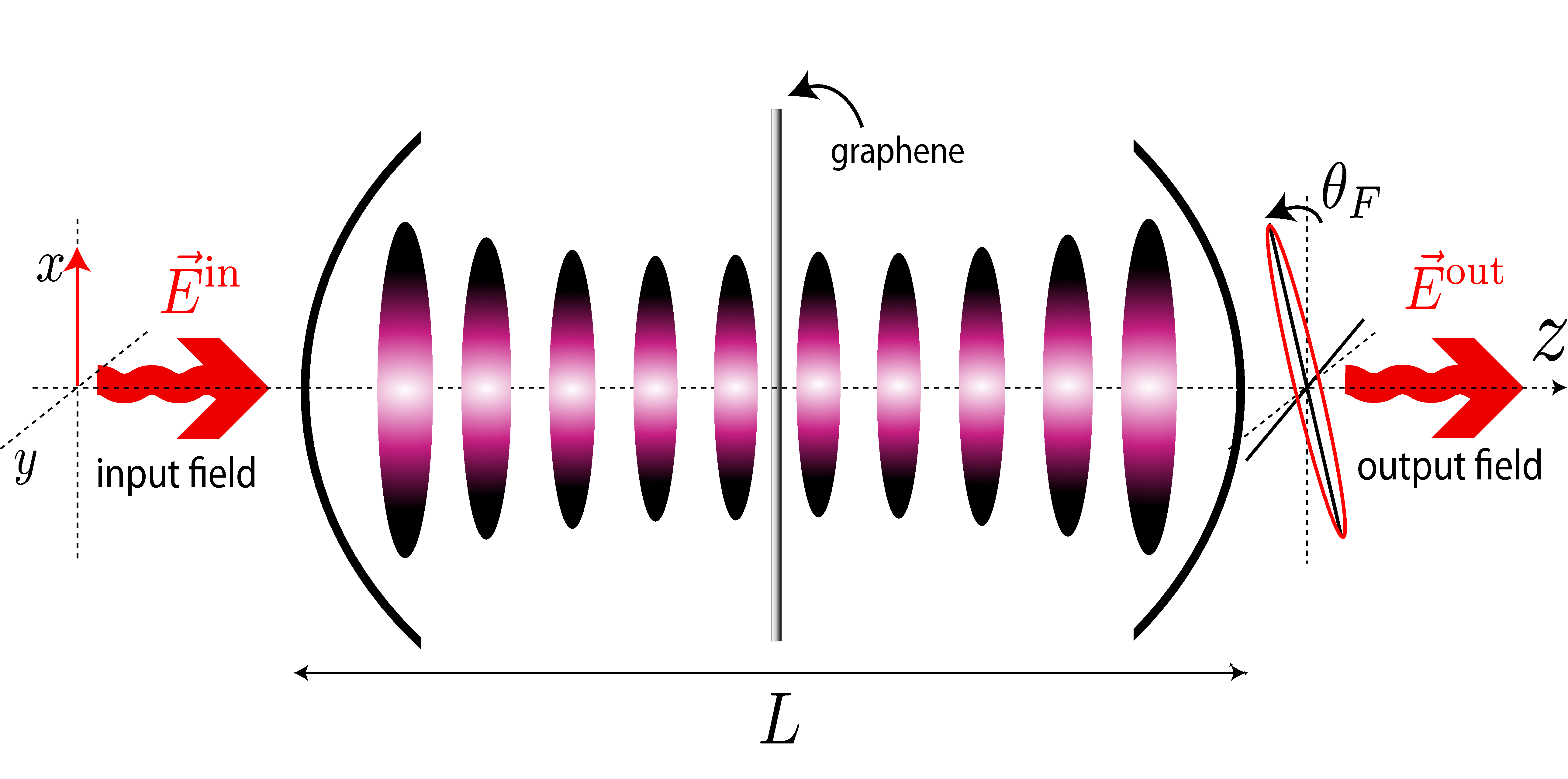
Refer to caption
Figure 16: Schematic of the graphene-optical cavity system: linearly polarized light shines into an optical cavity with graphene placed at the center. The field inside the cavity perceives graphene as an extra boundary and hence the two halves of the cavity operate as independent cavities of effective size L/2𝐿2L/2. Matching the light frequency ℏ​ωPlanck-constant-over-2-piπœ”\hbar\omega with a resonant frequency of the cavity Ο‰=n​π​c/Lπœ”π‘›πœ‹π‘πΏ\omega=n\pi c/L (nβˆˆβ„•π‘›β„•n\in\mathbb{N} ) traps photons inside the cavity for several round trips. As a consequence, Faraday rotation accumulates due to multiple passages through graphene, leading to an output field with a large Faraday rotation.

Following the steps in Sec.Β III.1, we write the boundary conditions of the electromagnetic field in terms of circularly polarized waves. Employing similar notation, we define the input and output circular vector amplitudes,

𝓔±in=superscriptsubscript𝓔plus-or-minusinabsent\displaystyle\bm{\mathcal{E}}_{\pm}^{\textrm{in}}= (EΒ±in,EΒ±r)T,superscriptsuperscriptsubscript𝐸plus-or-minusinsuperscriptsubscript𝐸plus-or-minusr𝑇\displaystyle\left(E_{\pm}^{\textrm{in}}\,,E_{\pm}^{\textrm{r}}\right)^{T}\,, (105)
𝓔±out=superscriptsubscript𝓔plus-or-minusoutabsent\displaystyle\bm{\mathcal{E}}_{\pm}^{\textrm{out}}= (EΒ±t,0)T,superscriptsuperscriptsubscript𝐸plus-or-minust0𝑇\displaystyle\left(E_{\text{$\pm$}}^{\textrm{t}}\,,0\right)^{T}\,, (106)

respectively (see also Fig.Β 16), where EΒ±in=ExinΒ±i​Eyinsuperscriptsubscript𝐸plus-or-minusinplus-or-minussuperscriptsubscript𝐸π‘₯in𝑖superscriptsubscript𝐸𝑦inE_{\pm}^{\textrm{in}}=E_{x}^{\textrm{in}}\pm iE_{y}^{\textrm{in}} (the reflected EΒ±rsuperscriptsubscript𝐸plus-or-minusrE_{\pm}^{\textrm{r}} and transmitted waves EΒ±tsuperscriptsubscript𝐸plus-or-minustE_{\text{$\pm$}}^{\textrm{t}} having analogous definitions). The first (second) component of the vectors, Eq.Β (105) and (106), refers to the complex amplitude of light traveling in the positive (negative) z𝑧z direction.

The output field, 𝓔±outsuperscriptsubscript𝓔plus-or-minusout\bm{\mathcal{E}}_{\pm}^{\textrm{out}}, and thus the total Faraday rotation angle, can be more conveniently computed using the transfer matrix formalism. The method is explained in detail in AppendixΒ A. Here, we just state the basic results: the T𝑇TΒ matrix, by definition, connects the input and output vector amplitudes, according to

𝓔±in=TΒ±inβ†’out​𝓔±out,superscriptsubscript𝓔plus-or-minusinsuperscriptsubscript𝑇plus-or-minusβ†’inoutsuperscriptsubscript𝓔plus-or-minusout\bm{\mathcal{E}}_{\pm}^{\textrm{in}}=T_{\pm}^{\textrm{in}\rightarrow\textrm{out}}\bm{\mathcal{E}}_{\pm}^{\textrm{out}}\,, (107)

where TΒ±inβ†’outsuperscriptsubscript𝑇plus-or-minusβ†’inoutT_{\pm}^{\textrm{in}\rightarrow\textrm{out}} is a product of individual transfer matrices for each boundary (optical component, metallic surface, etc.). Its inverse permits us to compute 𝓔±outsuperscriptsubscript𝓔plus-or-minusout\bm{\mathcal{E}}_{\pm}^{\textrm{out}}, given the input field 𝓔±insuperscriptsubscript𝓔plus-or-minusin\bm{\mathcal{E}}_{\pm}^{\textrm{in}}, and hence the optical characteristics of the cavity-graphene system. In particular, the circular transmitted amplitudes, tΒ±=EΒ±t/EΒ±insubscript𝑑plus-or-minussuperscriptsubscript𝐸plus-or-minustsuperscriptsubscript𝐸plus-or-minusint_{\pm}=E_{\text{$\pm$}}^{\textrm{t}}/E_{\pm}^{\textrm{in}}, are given by tΒ±=1/[TΒ±inβ†’out]1,1subscript𝑑plus-or-minus1subscriptdelimited-[]superscriptsubscript𝑇plus-or-minusβ†’inout11t_{\pm}=1/[T_{\pm}^{\textrm{in}\rightarrow\textrm{out}}]_{1,1}.

Refer to caption
Refer to caption
Figure 17: Faraday rotation angle of a cavity-graphene system in the semiclassical and quantum regimes. Top left:ΞΈFsubscriptπœƒπΉ\theta_{F} as a function of the photon energy for a cavity-graphene system in a magnetic field of 777Β T . The Fermi energy reads EF=0.3subscript𝐸𝐹0.3E_{F}=0.3Β eV and the cavity mirrors have r=0.99π‘Ÿ0.99r=0.99. Other parameters: Ξ“=10.5Ξ“10.5\Gamma=10.5Β meV and T=12𝑇12T=12Β K. Top right: ΞΈFsubscriptπœƒπΉ\theta_{F} versus the reflection amplitude rπ‘Ÿr for ℏ​ω=19Planck-constant-over-2-piπœ”19\hbar\omega=19Β meV. Bottom: In the left (right) panel, the Fermi energy reads EF=0.05subscript𝐸𝐹0.05E_{F}=0.05Β eV (EF=0.1subscript𝐸𝐹0.1E_{F}=0.1Β eV), which corresponds to an LL occupation of NF=0subscript𝑁𝐹0N_{F}=0 (NF=1subscript𝑁𝐹1N_{F}=1). The orange dashed line shows ΞΈFsubscriptπœƒπΉ\theta_{F} as obtained with the semiclassical conductivity tensor.

For the geometry posed in Fig.Β 16, the input-output T𝑇TΒ matrix reads

TΒ±inβ†’outsuperscriptsubscript𝑇plus-or-minusβ†’inout\displaystyle T_{\pm}^{\textrm{in}\rightarrow\textrm{out}} =\displaystyle= Tmβ‹…[eβˆ’i​ω​L/2​c00ei​ω​L/2​c]β‹…TΒ±gβ‹…subscript𝑇mdelimited-[]superscriptπ‘’π‘–πœ”πΏ2𝑐00superscriptπ‘’π‘–πœ”πΏ2𝑐superscriptsubscript𝑇plus-or-minusg\displaystyle T_{\textrm{m}}\cdot\left[\begin{array}[]{cc}e^{-i\omega L/2c}&0\\ 0&e^{i\omega L/2c}\end{array}\right]\cdot T_{\pm}^{\textrm{g}} (110)
β‹…[eβˆ’i​ω​L/2​c00ei​ω​L/2​c]β‹…Tm.β‹…absentβ‹…delimited-[]superscriptπ‘’π‘–πœ”πΏ2𝑐00superscriptπ‘’π‘–πœ”πΏ2𝑐subscript𝑇m\displaystyle\cdot\left[\begin{array}[]{cc}e^{-i\omega L/2c}&0\\ 0&e^{i\omega L/2c}\end{array}\right]\cdot T_{\textrm{m}}\,. (113)

Each operator in Eq.Β (113) propagates the electric field to the right until a boundary is reached. Tmsubscript𝑇mT_{\textrm{m}} encodes the effect of the first interface, a mirror, and depends only on the mirror’s transmission and reflection amplitudes, t𝑑t and rπ‘Ÿr, respectively. It can be written as

Tm=1i​|t|​[1|r|βˆ’|r|βˆ’1].subscript𝑇m1𝑖𝑑delimited-[]1π‘Ÿπ‘Ÿ1T_{\textrm{m}}=\frac{1}{i|t|}\left[\begin{array}[]{cc}1&|r|\\ -|r|&-1\end{array}\right]\,. (114)

(For a derivation, see, e.g., Ref.Β wavepropagation, .) After interaction with the left-end mirror, photons can enter into the cavity and propagate for a distance of L/2𝐿2L/2 before the next interaction. This means that another T𝑇TΒ matrix is needed; free propagation merely adds a phase to the electric field [see Eq.Β (122) and text thereafter] and thus is represented by a diagonal matrix, which is the second operator in Eq.Β (113). At z=L/2𝑧𝐿2z=L/2, photons arrive at the air-graphene-air interface, whose T𝑇TΒ matrix we denote by TΒ±gsuperscriptsubscript𝑇plus-or-minusgT_{\pm}^{\textrm{g}}. (More involved types of interfaces could be considered: for example, air-substrate-graphene-air. The present choice has the advantage of keeping the mathematical expressions elegant; generalization to other configurations using the present formalism is straightforward.) The graphene’s T𝑇TΒ matrix depends on the magnetic field intensity, electronic density, temperature, and LL broadening, via the complex optical conductivity of graphene σ±​(Ο‰)subscript𝜎plus-or-minusπœ”\sigma_{\pm}(\omega); its explicit form is

TΒ±g=12​[2+Z0β€‹Οƒβˆ“β€‹(Ο‰)Z0β€‹Οƒβˆ“β€‹(Ο‰)βˆ’Z0β€‹Οƒβˆ“β€‹(Ο‰)2βˆ’Z0β€‹Οƒβˆ“β€‹(Ο‰)],superscriptsubscript𝑇plus-or-minusg12delimited-[]2subscript𝑍0subscript𝜎minus-or-plusπœ”subscript𝑍0subscript𝜎minus-or-plusπœ”subscript𝑍0subscript𝜎minus-or-plusπœ”2subscript𝑍0subscript𝜎minus-or-plusπœ”T_{\pm}^{\textrm{g}}=\frac{1}{2}\left[\begin{array}[]{cc}2+Z_{0}\sigma_{\mp}(\omega)&Z_{0}\sigma_{\mp}(\omega)\\ -Z_{0}\sigma_{\mp}(\omega)&2-Z_{0}\sigma_{\mp}(\omega)\end{array}\right]\,, (115)

where Z0=ΞΌ0​csubscript𝑍0subscriptπœ‡0𝑐Z_{0}=\mu_{0}c denotes the vacuum impedance; see AppendixΒ A for a detailed derivation. Finally, the second line of Eq.Β (113) propagates the field in free space for a distance of L/2𝐿2L/2 and adds the right-end mirror.

The Faraday rotation angle is obtained from ΞΈF=(1/2)​arg​(t+/tβˆ’)subscriptπœƒπΉ12argsubscript𝑑subscript𝑑\theta_{F}=(1/2)\textrm{arg}(t_{+}/t_{-}), with the circular amplitude ratio t+/tβˆ’subscript𝑑subscript𝑑t_{+}/t_{-} given by [Tβˆ’inβ†’out]1,1/[T+inβ†’out]1,1subscriptdelimited-[]superscriptsubscript𝑇→inout11subscriptdelimited-[]superscriptsubscript𝑇→inout11[T_{-}^{\textrm{in}\rightarrow\textrm{out}}]_{1,1}/[T_{+}^{\textrm{in}\rightarrow\textrm{out}}]_{1,1} [Eq.Β (124)]. After some algebra, we arrive at

t+tβˆ’=2+Z0​σ+​(Ο‰)βˆ’|r|​[Z0​σ+​(Ο‰)βˆ’2]​ei​ω​L/c2+Z0β€‹Οƒβˆ’β€‹(Ο‰)βˆ’|r|​[Z0β€‹Οƒβˆ’β€‹(Ο‰)βˆ’2]​ei​ω​L/c,subscript𝑑subscript𝑑2subscript𝑍0subscriptπœŽπœ”π‘Ÿdelimited-[]subscript𝑍0subscriptπœŽπœ”2superscriptπ‘’π‘–πœ”πΏπ‘2subscript𝑍0subscriptπœŽπœ”π‘Ÿdelimited-[]subscript𝑍0subscriptπœŽπœ”2superscriptπ‘’π‘–πœ”πΏπ‘\frac{t_{+}}{t_{-}}=\frac{2+Z_{0}\sigma_{+}(\omega)-|r|\left[Z_{0}\sigma_{+}(\omega)-2\right]e^{i\omega L/c}}{2+Z_{0}\sigma_{-}(\omega)-|r|\left[Z_{0}\sigma_{-}(\omega)-2\right]e^{i\omega L/c}}\,, (116)

from which ΞΈFsubscriptπœƒπΉ\theta_{F} can be immediately deduced. Setting r=0π‘Ÿ0r=0 in the latter expression leads to the previous result in the absence of a cavity [compare with tΒ±subscript𝑑plus-or-minust_{\pm} as obtained from Eq.Β (88) with Ο΅r=1subscriptitalic-Ο΅π‘Ÿ1\epsilon_{r}=1].

When r>0π‘Ÿ0r>0, interference takes place and photons can make several round trips before being transmitted through the cavity. On an intuitive basis, we then expect that the Faraday rotation angle can be enhanced due to multiple passages of photons through graphene, which indeed is the case, as shown in Fig.Β 17. Hereafter, the size of the cavity is set to L=n​π​c/Ο‰πΏπ‘›πœ‹π‘πœ”L=n\pi c/\omega, with n𝑛n odd. The solid line shows ΞΈFsubscriptπœƒπΉ\theta_{F} for the cavity-graphene system and the dashed-dotted line shows ΞΈFsubscriptπœƒπΉ\theta_{F} for free-standing graphene for the same parameters: clearly, in the range of frequencies considered, the Faraday effect is greatly enhanced. For example, for a low frequency, β„β€‹Ο‰β‰ˆ10Planck-constant-over-2-piπœ”10\hbar\omega\approx 10 meV, ΞΈFsubscriptπœƒπΉ\theta_{F} has increased by a factor of about 555, reaching a value of 55Β degrees, whereas for β„β€‹Ο‰β‰ˆ19Planck-constant-over-2-piπœ”19\hbar\omega\approx 19Β meV, ΞΈFsubscriptπœƒπΉ\theta_{F} increases by a factor of about 202020, reaching a value of approximately 25Β degrees.

Direct inspection of Eq.Β (116) discloses the observed boost of the Faraday effect: when rβ†’1β†’π‘Ÿ1r\rightarrow 1 and the phase factor exp​(i​ω​L/c)=βˆ’1expπ‘–πœ”πΏπ‘1\textrm{exp}(i\omega L/c)=-1, the constant factor of 222 cancels in both the denominator and the numerator, leading to,

|t+tβˆ’|​e2​i​θF​≃n​oddr≃1​σ+​(Ο‰)Οƒβˆ’β€‹(Ο‰),subscript𝑑subscript𝑑superscript𝑒2𝑖subscriptπœƒπΉsimilar-to-or-equalsπ‘Ÿ1𝑛oddsimilar-to-or-equalssubscriptπœŽπœ”subscriptπœŽπœ”\left|\frac{t_{+}}{t_{-}}\right|e^{2i\theta_{F}}\underset{\underset{r\simeq 1}{n\>\textrm{odd}}}{\simeq}\frac{\sigma_{+}(\omega)}{\sigma_{-}(\omega)}, (117)

which can present large arguments, 2​θF2subscriptπœƒπΉ2\theta_{F}. The opposite limit, rβ†’0β†’π‘Ÿ0r\rightarrow 0, in which the isolated graphene system is recovered, leads to much smaller arguments, since generally 2≫Z0​Im​σ±much-greater-than2subscript𝑍0Imsubscript𝜎plus-or-minus2\gg Z_{0}\textrm{Im}\,\sigma_{\pm}, which implies that the real part of Eq.Β (88) is predominant. Choosing a cavity mode with n𝑛n odd and r≃1similar-to-or-equalsπ‘Ÿ1r\simeq 1 is fully equivalent to taking a large number of equally prepared graphene sheets placed in a row (AppendixΒ B). The cavity geometry therefore permits us to take advantage of large Faraday rotation accumulation using a single graphene sheet.

In a cavity geometry, the Faraday rotation is no longer dominated by the behavior of Οƒx​y′​(Ο‰)superscriptsubscript𝜎π‘₯π‘¦β€²πœ”\sigma_{xy}^{\prime}(\omega) [see Eq.Β (94)], for ΞΈFsubscriptπœƒπΉ\theta_{F} now depends on the full conductivity tensor [Eq.Β (117)]. The most visible consequence of the latter fact is that photons with β„β€‹Ο‰β‰ˆ20Planck-constant-over-2-piπœ”20\hbar\omega\approx 20Β meV undergo considerable Faraday rotation angles in a cavity geometry, whereas, in a single passage through graphene, photons with such energy do not produce Faraday rotation at all (Fig.Β 17). This apparently counter-intuitive result is due to induced ellipticity in single passages and is explained in AppendixΒ B.

Refer to caption
Refer to caption
Figure 18: Faraday rotation boost in the infrared and visible ranges. Left: Faraday rotation angle versus photon energy of a cavity-graphene system with EF=0.85subscript𝐸𝐹0.85E_{F}=0.85Β eV (top) and EF=0.3subscript𝐸𝐹0.3E_{F}=0.3Β eV (bottom). Right: Transmissivity of a cavity-graphene system for the same parameters considered at the left panels. Inset: Transmissivity of intrinsic graphene for the same parameters. Other parameters as in Fig.Β 17. In order to obtain a measurable Faraday rotation at β„β€‹Ο‰β‰ˆ1.7Planck-constant-over-2-piπœ”1.7\hbar\omega\approx 1.7Β eV [solid (red) line] [β„β€‹Ο‰β‰ˆ0.5Planck-constant-over-2-piπœ”0.5\hbar\omega\approx 0.5Β eV (infrared)], it is necessary to tune the intraband resonance according to EF≃ℏ​ω/2similar-to-or-equalssubscript𝐸𝐹Planck-constant-over-2-piπœ”2E_{F}\simeq\hbar\omega/2.

a. Semi-classical versus quantum regimes in a cavity geometryβ€”FigureΒ 17 (top) considers the case of EF=0.3subscript𝐸𝐹0.3E_{F}=0.3Β eV and B=7𝐡7B=7Β T, well inside the semiclassical regime, for which the ac conductivity is dominated by intraband contributions over a wide range of frequencies (Sec.Β II); the corresponding intraband Faraday rotation is seen to be greatly enhanced in the cavity geometry.

The low-electronic-density regime of the cavity-graphene system is shown in the bottom panel in Fig.Β 17. Remarkably, for energies above the interband threshold, namely, ℏ​ω≳E1≃95greater-than-or-equivalent-toPlanck-constant-over-2-piπœ”subscript𝐸1similar-to-or-equals95\hbar\omega\gtrsim E_{1}\simeq 95Β meV for NF=0subscript𝑁𝐹0N_{F}=0 (left) and ℏ​ω≳E1+E2≃230greater-than-or-equivalent-toPlanck-constant-over-2-piπœ”subscript𝐸1subscript𝐸2similar-to-or-equals230\hbar\omega\gtrsim E_{1}+E_{2}\simeq 230Β meV for NF=1subscript𝑁𝐹1N_{F}=1 (right), ΞΈF​(Ο‰)subscriptπœƒπΉπœ”\theta_{F}(\omega) presents a behavior qualitative different from that of an isolated graphene sheet (black dot double-dashed curve): oscillations do emerge. These oscillations are hindered in single-photon passages through graphene (see also Fig.Β 13), but for multiple-photon passages, in the high-frequency limit, Shubnikov–de Haas oscillations in the longitudinal conductivity Οƒx​x​(Ο‰)subscript𝜎π‘₯π‘₯πœ”\sigma_{xx}(\omega) (Fig.Β 4) are critical in defining the orientation of light polarization axes. These oscillations are obviously absent in the semiclassical Boltzmann calculation [dashed (orange) curve]. In the top panel, where EF=0.3subscript𝐸𝐹0.3E_{F}=0.3Β eV, such oscillations are not present because the represented photon energies are well below the threshold for interband transitions ℏ​ω≃2​EFsimilar-to-or-equalsPlanck-constant-over-2-piπœ”2subscript𝐸𝐹\hbar\omega\simeq 2E_{F}.

b. Near-infrared and visible-range Faraday rotationβ€”We finish this section by mentioning an important application of the cavity-graphene system: interband-induced Faraday rotations in the near-infrared and visible regimes. FigureΒ 18 shows that energetic photons can attain ΞΈF≳1greater-than-or-equivalent-tosubscriptπœƒπΉ1\theta_{F}\gtrsim 1 by tuning the Fermi energy to sufficiently high values. In this regard, the top panel shows numerical data for graphene with EF=0.85subscript𝐸𝐹0.85E_{F}=0.85 eV; such a high doping level of graphene samples is feasible using chemically synthesized graphene with ferroelectric substrates (instead of the conventional SiO2).Wafer-scale_Graphene

Given the mirror reflection amplitude considered, r=0.99π‘Ÿ0.99r=0.99, photons are trapped for a large number of round trips. This means that it is highly probable that photons get absorbed by graphene before leaking into the cavity. This explains why the transmissivity of the cavity-graphene system, as shown in the right panel in Fig.Β 18, is well below 1 (but still large enough that the effect can be measured). One way of increasing the transmissivity of a cavity-graphene system is to decrease the quality of the mirrors, at the expense of decreasing the maximum achievable ΞΈFsubscriptπœƒπΉ\theta_{F}.

We, finally, remark that the nonlinearity associated with next-neighbor hopping tβ€²superscript𝑑′t^{\prime} in a honeycomb graphene lattice can play a role for photons with ℏ​ω≳1greater-than-or-equivalent-toPlanck-constant-over-2-piπœ”1\hbar\omega\gtrsim 1Β eV, and hence corrections to the Dirac cone approximation (Sec.Β II.1), and thus to the EOM solutions, may exist; such corrections are expected to be very small, however.Stauber_VisibleReg

IV Conclusion and outlook

In the first part of this work, the EOM method has been adapted to the study of magneto-optical transport of electronic systems. To illustrate the method, the magneto-optical conductivity tensor of single-layer graphene in the Dirac cone approximation has been derived, accounting for both intraband (semi-classical) transitions and interband transitions between the valence and the conduction bands.

The general regularization procedure to obtain the regular conductivity tensor from the solutions of the EOM for the current operator has been established; this procedure is shown to lead to the correct formulas without the need for evaluation of the Kubo formula. To the best of the authors’ knowledge, such a procedure has not been discussed in the literature so far. In addition, quantitative comparisons between the quantum EOM solutions and the semiclassical Boltzmann formulas, in the full optical spectrum, and in both low- and high-doped graphene samples, have been given throughout.

In the second part, the Faraday rotation effect in single-layer graphene has been studied in detail; in particular, simple formulas for the step heights in the quantum Hall regime have been derived. Our results have been shown to account well for available experimental data in the semiclassical regime.

Finally, we have proposed a simple experimental apparatus based on an optical cavity that leads to an enhancement of the Faraday rotation effect of graphene by orders of magnitude, thus allowing to obtain giant Faraday rotation angles in the infrared region and modest Faraday rotation angles in the visible region.

We hope that the present work further stimulates the research on magneto-optical properties of ultrathin 2D gases and graphene-based solid-state devices.

Acknowledgments

A.F. acknowledges FCT Grant No. SFRH/BPD/65600/2009. N.M.R.P. acknowledges Fundos FEDER, through the Programa Operacional Factores de Competitividade - COMPETE and by FCT under Project No. Past-C/FIS/UI0607/2011. A.H.C.N. acknowledges support from the DOE Grant No. DE-FG02-08ER46512 and the ONR Grant No. MURI N00014-09-1-1063.

Appendix A Transfer matrix formalism

The transfer matrix (T𝑇TΒ matrix) approach is a widely used method in optics and related fields and provides an efficient means of calculating the amplitude and phase of transmitted electric fields through an arbitrary number of interfaces. In this appendix, we give a self-contained review of the method and derive explicitly the T𝑇TΒ matrix for a general 2D conducting media.

A.1 General formalism

For concreteness, we assume that an incident electromagnetic wave of frequency Ο‰πœ”\omega, travels in the z𝑧z direction through a set of N𝑁N metallic interfaces, placed normal to the direction of propagation, with labels Ξ±n,n+1subscript𝛼𝑛𝑛1\alpha_{n,n+1}, and located at positions z=zn𝑧subscript𝑧𝑛z=z_{n} (n∈1,2,…​N𝑛12…𝑁n\in 1,2,...N). These interfaces are separated by dielectric mediums β€” Fig.Β 19 shows the configuration we have in mind.

The electric field is separated according to the direction of propagation: 𝑬n+​(z)superscriptsubscript𝑬𝑛𝑧\bm{E}_{n}^{+}(z) represents the part the electric field traveling in the positive direction of z𝑧z, within the region n𝑛n, whereas 𝑬nβˆ’β€‹(z)superscriptsubscript𝑬𝑛𝑧\bm{E}_{n}^{-}(z) represents the part traveling in the opposite direction.

As shown below, the calculation of transmitted and reflected amplitudes becomes easier by writing the boundary conditions in terms of circularly polarized waves (see also Sec.Β III.1). Therefore, we focus on the circular amplitudes,

En,τ±​(z)=En,x±​(z)+i​τ​En,yΒ±,superscriptsubscriptπΈπ‘›πœplus-or-minus𝑧superscriptsubscript𝐸𝑛π‘₯plus-or-minusπ‘§π‘–πœsuperscriptsubscript𝐸𝑛𝑦plus-or-minusE_{n,\tau}^{\pm}(z)=E_{n,x}^{\pm}(z)+i\tau E_{n,y}^{\pm}\,, (118)

where Ο„πœ\tau is the polarization index: Ο„=Β±1𝜏plus-or-minus1\tau=\pm 1 [+11+1(βˆ’11-1) means right-handed (left-handed) circular polarization]. Indeed, in a given region i𝑖i, the total (complex) electric field is the sum of both components,

𝑬n​(z,t)=𝑬n+​(z)​eβˆ’i​ω​t+𝑬nβˆ’β€‹(z)​eβˆ’i​ω​t.subscript𝑬𝑛𝑧𝑑superscriptsubscript𝑬𝑛𝑧superscriptπ‘’π‘–πœ”π‘‘superscriptsubscript𝑬𝑛𝑧superscriptπ‘’π‘–πœ”π‘‘\bm{E}_{n}(z,t)=\bm{E}_{n}^{+}(z)e^{-i\omega t}+\bm{E}_{n}^{-}(z)e^{-i\omega t}\,. (119)

The physical electric field is obtained by taking the real part of the latter expression. We omit the time-dependence in the remainder of the appendix.
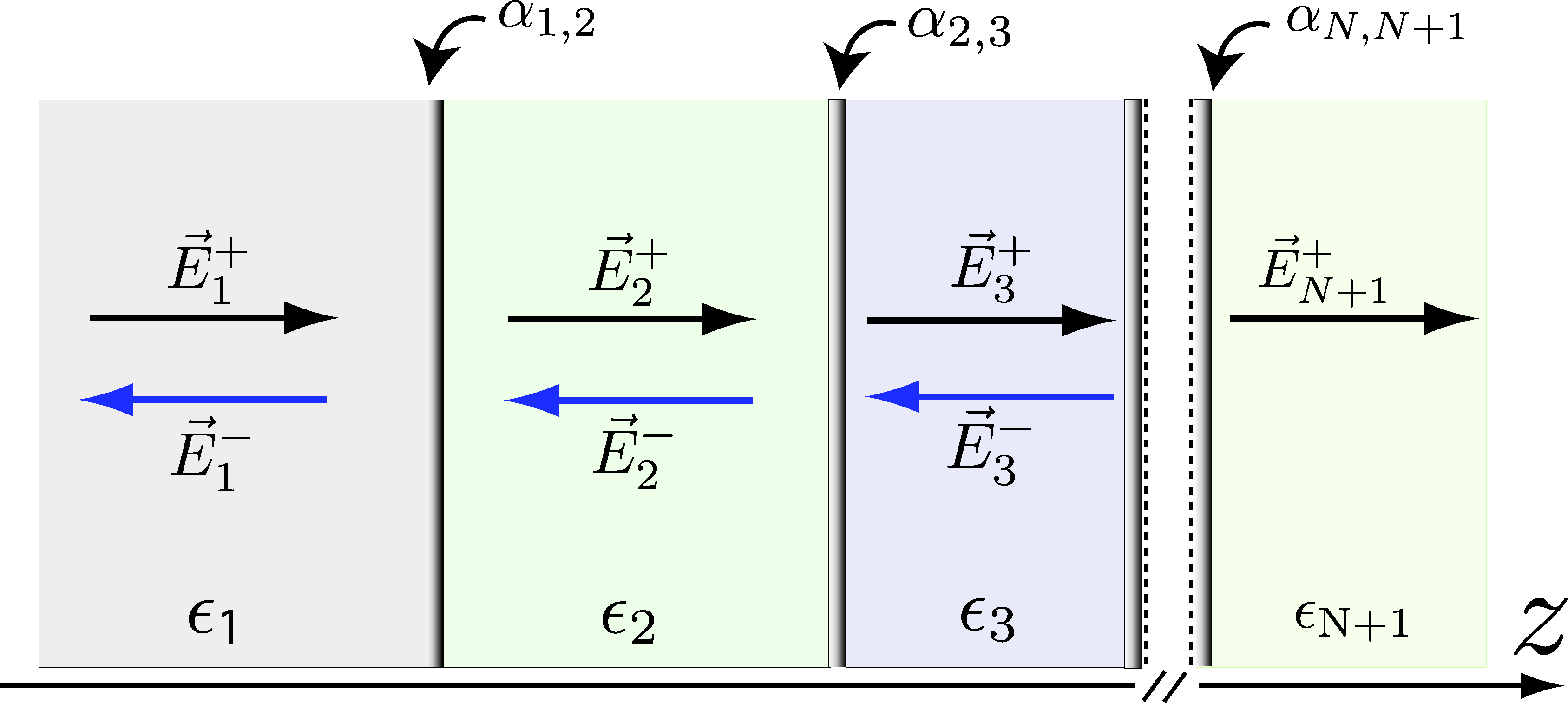
Refer to caption
Figure 19: Schematic of an optical system consisting of an array of interfaces separated by different types of dielectric media. An electromagnetic wave, 𝑬in=𝑬1+superscript𝑬insuperscriptsubscript𝑬1\bm{E}^{\textrm{in}}=\bm{E}_{1}^{+}, coming from a medium with dielectric permittivity Ο΅1subscriptitalic-Ο΅1\epsilon_{1} interacts with an interface Ξ±12subscript𝛼12\alpha_{12}. As a result, it is partially reflected and partially transmitted into the medium Ο΅2subscriptitalic-Ο΅2\epsilon_{2}. Equivalent events take place at the remaining interfaces. The vectors with superscript ++(βˆ’-) denote the component of the electric field traveling in the positive (negative) direction of z𝑧z. A uniform static magnetic field 𝐁=Bβ€‹πžπ²ππ΅subscript𝐞𝐲\mathbf{B}=B\mathbf{e_{y}} is assumed.

The T𝑇TΒ matrix connects the amplitude of the electric field to the left and to the right of a given boundary (interface). Take for instance, the interface labeled Ξ±1,2subscript𝛼12\alpha_{1,2} in Fig.Β 19. The respective T𝑇TΒ matrix, T^1,2superscript^𝑇12\hat{T}^{1,2}, is defined as,

(E2,Ο„+​(z1+)E2,Ο„βˆ’β€‹(z1+))=T^Ο„1,2​(E1,Ο„+​(z1βˆ’)E1,Ο„βˆ’β€‹(z1βˆ’)),superscriptsubscript𝐸2𝜏superscriptsubscript𝑧1superscriptsubscript𝐸2𝜏superscriptsubscript𝑧1superscriptsubscript^π‘‡πœ12superscriptsubscript𝐸1𝜏superscriptsubscript𝑧1superscriptsubscript𝐸1𝜏superscriptsubscript𝑧1\left(\begin{array}[]{c}E_{2,\tau}^{+}(z_{1}^{+})\\ E_{2,\tau}^{-}(z_{1}^{+})\end{array}\right)=\hat{T}_{\tau}^{1,2}\left(\begin{array}[]{c}E_{1,\tau}^{+}(z_{1}^{-})\\ E_{1,\tau}^{-}(z_{1}^{-})\end{array}\right)\,, (120)

where z1Β±superscriptsubscript𝑧1plus-or-minusz_{1}^{\pm} denote the position where the electric field is to be evaluated: right after (++) or before (βˆ’-) the interface located at z=z1𝑧subscript𝑧1z=z_{1}. For ease of notation, we define the vector of amplitudes,

𝓔n,τ​(z)=(En,Ο„+​(z)En,Ο„βˆ’β€‹(z)),subscriptπ“”π‘›πœπ‘§superscriptsubscriptπΈπ‘›πœπ‘§superscriptsubscriptπΈπ‘›πœπ‘§\mathcal{\bm{E}}_{n,\tau}(z)=\left(\begin{array}[]{c}E_{n,\tau}^{+}(z)\\ E_{n,\tau}^{-}(z)\end{array}\right)\,, (121)

and drop the superscripts in the coordinates znsubscript𝑧𝑛z_{n}.

If more than one interface is present, the light propagates a given distance before interacting with the next component. Propagation of light through a dielectric medium merely adds a phase to each Ο„πœ\tau circular component of the electric field. Indeed, its action can be represented by a diagonal matrix,

𝓔n,τ​(zi)=[eβˆ’i​kn​Δ​zn00ei​kn​Δ​zn]​𝓔n,τ​(zi+1),subscriptπ“”π‘›πœsubscript𝑧𝑖delimited-[]superscript𝑒𝑖subscriptπ‘˜π‘›Ξ”subscript𝑧𝑛00superscript𝑒𝑖subscriptπ‘˜π‘›Ξ”subscript𝑧𝑛subscriptπ“”π‘›πœsubscript𝑧𝑖1\mathcal{\bm{E}}_{n,\tau}(z_{i})=\left[\begin{array}[]{cc}e^{-ik_{n}\Delta z_{n}}&0\\ 0&e^{ik_{n}\Delta z_{n}}\end{array}\right]\mathcal{\bm{E}}_{n,\tau}(z_{i+1})\,, (122)

where the index n𝑛n just takes the values for which there is intermediate light propagation, i.e., n=1,…,Nβˆ’1𝑛1…𝑁1n=1,...,N-1, the wave vector depends on the dielectric medium according to kn=ω​ϡn/csubscriptπ‘˜π‘›πœ”subscriptitalic-ϡ𝑛𝑐k_{n}=\omega\sqrt{\epsilon_{n}}/c and Δ​zn=zn+1βˆ’znΞ”subscript𝑧𝑛subscript𝑧𝑛1subscript𝑧𝑛\Delta z_{n}=z_{n+1}-z_{n} is the width of the region n𝑛n. Note that Eq.Β (122) defines a particular case of a T𝑇TΒ matrix, which we denote by F^nsubscript^𝐹𝑛\hat{F}_{n}.

The problem of finding how the output electric field, of definite polarization Ο„πœ\tau, immediately after leaving the last interface, EN+1,Ο„+​(zN)superscriptsubscript𝐸𝑁1𝜏subscript𝑧𝑁E_{N+1,\tau}^{+}(z_{N}), relates to the incoming electric field, with the same polarization Ο„πœ\tau, E1,Ο„+​(z1)superscriptsubscript𝐸1𝜏subscript𝑧1E_{1,\tau}^{+}(z_{1}), then amounts to take the product of the individual transfer matrices,

𝓔1,τ​(z1)=T^Ο„1,2​F^2​T^Ο„2,3​…​T^Ο„Nβˆ’1,N​F^N​T^Ο„N,N+1⏟T^Ο„inβ†’out​𝓔N+1,τ​(zN).subscript𝓔1𝜏subscript𝑧1superscriptsubscript^π‘‡πœβ†’inout⏟superscriptsubscript^π‘‡πœ12subscript^𝐹2superscriptsubscript^π‘‡πœ23…superscriptsubscript^π‘‡πœπ‘1𝑁subscript^𝐹𝑁superscriptsubscript^π‘‡πœπ‘π‘1subscript𝓔𝑁1𝜏subscript𝑧𝑁\mathcal{\bm{E}}_{1,\tau}(z_{1})=\underset{\hat{T}_{\tau}^{\textrm{in}\rightarrow\textrm{out}}}{\underbrace{\hat{T}_{\tau}^{1,2}\hat{F}_{2}\hat{T}_{\tau}^{2,3}...\hat{T}_{\tau}^{N-1,N}\hat{F}_{N}\hat{T}_{\tau}^{N,N+1}}}\mathcal{\bm{E}}_{N+1,\tau}(z_{N})\,. (123)

The total T𝑇TΒ matrix T^Ο„inβ†’outsuperscriptsubscript^π‘‡πœβ†’inout\hat{T}_{\tau}^{\textrm{in}\rightarrow\textrm{out}} has the desired information:

EN+1,Ο„+E1,Ο„+=1/[T^Ο„inβ†’out]1,1.superscriptsubscript𝐸𝑁1𝜏superscriptsubscript𝐸1𝜏1subscriptdelimited-[]superscriptsubscript^π‘‡πœβ†’inout11\frac{E_{N+1,\tau}^{+}}{E_{1,\tau}^{+}}=1/\left[\hat{T}_{\tau}^{\textrm{in}\rightarrow\textrm{out}}\right]_{1,1}\,. (124)

As for the relation between the output field and the reflected field at the first boundary, E1,Ο„βˆ’β€‹(z1),superscriptsubscript𝐸1𝜏subscript𝑧1E_{1,\tau}^{-}(z_{1}), we obtain,

EN+1,Ο„+E1,Ο„βˆ’=1/[T^inβ†’out]2,1.superscriptsubscript𝐸𝑁1𝜏superscriptsubscript𝐸1𝜏1subscriptdelimited-[]superscript^𝑇→inout21\frac{E_{N+1,\tau}^{+}}{E_{1,\tau}^{-}}=1/\left[\hat{T}^{\textrm{in}\rightarrow\textrm{out}}\right]_{2,1}\,. (125)

In what follows, we show how to construct the T𝑇TΒ matrix for a general 2D conducting medium. Knowledge of the transfer matrices allows us to determine the characteristics of transmitted and reflected light through a general set of conducting 2D thin films, mirrors, etc., by employing Eq.Β (123).

A.2 T𝑇T matrix for a general conducting 2D interface

We restrict the present derivation to non-magnetic media, and assume the standard constitutive relations hold,

𝑫​(𝐫,Ο‰)π‘«π«πœ”\displaystyle\bm{D}(\mathbf{r},\omega) =\displaystyle= ϡ​(𝐫,Ο‰)​𝑬​(𝐫,Ο‰),italic-Ο΅π«πœ”π‘¬π«πœ”\displaystyle\epsilon(\mathbf{r},\omega)\bm{E}(\mathbf{r},\omega)\,, (126)
𝑱​(𝐫,Ο‰)π‘±π«πœ”\displaystyle\bm{J}(\mathbf{r},\omega) =\displaystyle= Οƒ^​(𝐫,Ο‰)​𝑬​(𝐫,Ο‰),^πœŽπ«πœ”π‘¬π«πœ”\displaystyle\hat{\sigma}(\mathbf{r},\omega)\bm{E}(\mathbf{r},\omega)\,, (127)

where 𝑫𝑫\bm{D}, Ο΅italic-Ο΅\epsilon, and ΟƒπœŽ\sigma denote the displacement field, permittivity and conductivity, respectively. Also, and without prejudice, we take the 2D conducting interface to be located at z=0𝑧0z=0. The T𝑇TΒ matrix is defined as

(Ea,Ο„+​(z=0βˆ’)Ea,Ο„βˆ’β€‹(z=0βˆ’))=T^Ο„(a​b)​(Eb,Ο„+​(z=0+)Eb,Ο„βˆ’β€‹(z=0+)),superscriptsubscriptπΈπ‘Žπœπ‘§superscript0superscriptsubscriptπΈπ‘Žπœπ‘§superscript0superscriptsubscript^π‘‡πœπ‘Žπ‘superscriptsubscriptπΈπ‘πœπ‘§superscript0superscriptsubscriptπΈπ‘πœπ‘§superscript0\left(\begin{array}[]{c}E_{a,\tau}^{+}(z=0^{-})\\ E_{a,\tau}^{-}(z=0^{-})\end{array}\right)=\hat{T}_{\tau}^{(ab)}\left(\begin{array}[]{c}E_{b,\tau}^{+}(z=0^{+})\\ E_{b,\tau}^{-}(z=0^{+})\end{array}\right)\,, (128)

where aπ‘Ža (b𝑏b) is the bookkeeping index for the medium at the left (right) of the interface.

Various constraints emerge due to continuity of 𝑬𝑬\bm{E} (and its derivative) at the 2D conducting interface. Indeed, Maxwell equations imply that,

𝑬a​(0)subscriptπ‘¬π‘Ž0\displaystyle\bm{E}_{a}(0) =\displaystyle= 𝑬b​(0),subscript𝑬𝑏0\displaystyle\bm{E}_{b}(0)\,, (129)
(βˆ‚π‘¬aβˆ‚z)z=0βˆ’(βˆ‚π‘¬bβˆ‚z)z=0subscriptsubscriptπ‘¬π‘Žπ‘§π‘§0subscriptsubscript𝑬𝑏𝑧𝑧0\displaystyle\left(\frac{\partial\bm{E}_{a}}{\partial z}\right)_{z=0}-\left(\frac{\partial\bm{E}_{b}}{\partial z}\right)_{z=0} =\displaystyle= i​ω​μ0​σ^​𝑬b​(0),π‘–πœ”subscriptπœ‡0^𝜎subscript𝑬𝑏0\displaystyle i\omega\mu_{0}\hat{\sigma}\bm{E}_{b}(0)\,, (130)

where the conductivity tensor reads

Οƒ^=Οƒi​j​(Ο‰)​δ​(z).^𝜎subscriptπœŽπ‘–π‘—πœ”π›Ώπ‘§\hat{\sigma}=\sigma_{ij}(\omega)\delta(z)\,. (131)

The conductivity depends on the light frequency Ο‰πœ”\omega, and, generally, also on other quantities (Fermi energy of the interface, temperature, etc.). In the latter expression, the subscripts i,j=x,yformulae-sequence𝑖𝑗π‘₯𝑦i,j=x,y are Cartesian coordinates. In terms of circularly polarized fields, Eq.Β (130) reads,

ka​(Ea,Ο„+βˆ’Ea,Ο„βˆ’)βˆ’kb​(Eb,Ο„+βˆ’Eb,Ο„βˆ’)subscriptπ‘˜π‘ŽsuperscriptsubscriptπΈπ‘ŽπœsuperscriptsubscriptπΈπ‘Žπœsubscriptπ‘˜π‘superscriptsubscriptπΈπ‘πœsuperscriptsubscriptπΈπ‘πœ\displaystyle k_{a}(E_{a,\tau}^{+}-E_{a,\tau}^{-})-k_{b}(E_{b,\tau}^{+}-E_{b,\tau}^{-}) =ωμ0Γ—\displaystyle=\omega\mu_{0}\times
Γ—(Eb,Ο„++Eb,Ο„βˆ’)β€‹Οƒβˆ’Ο„β€‹(Ο‰),absentsuperscriptsubscriptπΈπ‘πœsuperscriptsubscriptπΈπ‘πœsubscriptπœŽπœπœ”\displaystyle\times(E_{b,\tau}^{+}+E_{b,\tau}^{-})\sigma_{-\tau}(\omega)\,, (132)

where we have admitted an isotropic medium, Οƒx​x=Οƒy​ysubscript𝜎π‘₯π‘₯subscriptπœŽπ‘¦π‘¦\sigma_{xx}=\sigma_{yy}, and have defined

σ±​(Ο‰)subscript𝜎plus-or-minusπœ”\displaystyle\sigma_{\pm}(\omega) =\displaystyle= Οƒx​x​(Ο‰)Β±i​σx​y​(Ο‰).plus-or-minussubscript𝜎π‘₯π‘₯πœ”π‘–subscript𝜎π‘₯π‘¦πœ”\displaystyle\sigma_{xx}(\omega)\pm i\sigma_{xy}(\omega)\,. (133)

The statement, Eq.Β (132), shows that the two circularly polarizations are decoupled, even in the presence of a complex conductivity σ±​(Ο‰)subscript𝜎plus-or-minusπœ”\sigma_{\pm}(\omega). This is why it is advantageous to write the boundary conditions in terms of circularly polarized fields (Sec.Β III.1).

According to the definition of the T𝑇TΒ matrix [Eq.Β (128)], we need to relate Ea,Ο„+superscriptsubscriptπΈπ‘ŽπœE_{a,\tau}^{+} with Eb,τ±superscriptsubscriptπΈπ‘πœplus-or-minusE_{b,\tau}^{\pm} and Ea,Ο„βˆ’superscriptsubscriptπΈπ‘ŽπœE_{a,\tau}^{-} with Eb,τ±superscriptsubscriptπΈπ‘πœplus-or-minusE_{b,\tau}^{\pm}, separately. To do so, we make use of the continuity condition, Eq.Β (129), written in circular waves, Ea,Ο„++Ea,Ο„βˆ’=Eb,Ο„++Eb,Ο„βˆ’superscriptsubscriptπΈπ‘ŽπœsuperscriptsubscriptπΈπ‘ŽπœsuperscriptsubscriptπΈπ‘πœsuperscriptsubscriptπΈπ‘πœE_{a,\tau}^{+}+E_{a,\tau}^{-}=E_{b,\tau}^{+}+E_{b,\tau}^{-}, in order to arrive at,

Β±2​ka​Ea,τ±plus-or-minus2subscriptπ‘˜π‘ŽsuperscriptsubscriptπΈπ‘Žπœplus-or-minus\displaystyle\pm 2k_{a}E_{a,\tau}^{\pm} =kb​(Eb,Ο„+βˆ’Eb,Ο„βˆ’)absentsubscriptπ‘˜π‘superscriptsubscriptπΈπ‘πœsuperscriptsubscriptπΈπ‘πœ\displaystyle=k_{b}(E_{b,\tau}^{+}-E_{b,\tau}^{-})
+[ω​μ0β€‹Οƒβˆ’Ο„β€‹(Ο‰)Β±ka]​(Eb,Ο„++Eb,Ο„βˆ’).delimited-[]plus-or-minusπœ”subscriptπœ‡0subscriptπœŽπœπœ”subscriptπ‘˜π‘ŽsuperscriptsubscriptπΈπ‘πœsuperscriptsubscriptπΈπ‘πœ\displaystyle+[\omega\mu_{0}\sigma_{-\tau}(\omega)\pm k_{a}](E_{b,\tau}^{+}+E_{b,\tau}^{-})\,. (134)

Combining Eq.Β (128) and the latter expression, we arrive at the desired result,

T^Ο„(a​b)=12​ka​[Λτ,++a​bΛτ,βˆ’+a​bΛτ,βˆ’βˆ’a​bΛτ,+βˆ’a​b],superscriptsubscript^π‘‡πœπ‘Žπ‘12subscriptπ‘˜π‘Ždelimited-[]superscriptsubscriptΞ›πœabsentπ‘Žπ‘superscriptsubscriptΞ›πœabsentπ‘Žπ‘superscriptsubscriptΞ›πœabsentπ‘Žπ‘superscriptsubscriptΞ›πœabsentπ‘Žπ‘\hat{T}_{\tau}^{(ab)}=\frac{1}{2k_{a}}\left[\begin{array}[]{cc}\Lambda_{\tau,++}^{ab}&\Lambda_{\tau,-+}^{ab}\\ \Lambda_{\tau,--}^{ab}&\Lambda_{\tau,+-}^{ab}\end{array}\right]\,, (135)

where

Λτ,Β±Β±a​b=kaΒ±kb±ω​μ0β€‹Οƒβˆ’Ο„β€‹(Ο‰).superscriptsubscriptΞ›πœplus-or-minusabsentplus-or-minusπ‘Žπ‘plus-or-minussubscriptπ‘˜π‘Žsubscriptπ‘˜π‘πœ”subscriptπœ‡0subscriptπœŽπœπœ”\Lambda_{\tau,\pm\pm}^{ab}=k_{a}\pm k_{b}\pm\omega\mu_{0}\sigma_{-\tau}(\omega)\,. (136)

A.3 Example: T𝑇T matrix of suspended graphene

The T𝑇TΒ matrix of suspended graphene can be obtained immediately from Eq.Β (133). Admitting that the mediums at the left and right of the single-layer graphene sheet are air, we obtain

T^Ο„graph=12​[2+Z0β€‹Οƒβˆ’Ο„graph​(Ο‰)Z0β€‹Οƒβˆ’Ο„graph​(Ο‰)βˆ’Z0β€‹Οƒβˆ’Ο„graph​(Ο‰)2βˆ’Z0β€‹Οƒβˆ’Ο„graph​(Ο‰)],superscriptsubscript^π‘‡πœgraph12delimited-[]2subscript𝑍0superscriptsubscript𝜎𝜏graphπœ”subscript𝑍0superscriptsubscript𝜎𝜏graphπœ”subscript𝑍0superscriptsubscript𝜎𝜏graphπœ”2subscript𝑍0superscriptsubscript𝜎𝜏graphπœ”\hat{T}_{\tau}^{\textrm{graph}}=\frac{1}{2}\left[\begin{array}[]{cc}2+Z_{0}\sigma_{-\tau}^{\textrm{graph}}(\omega)&Z_{0}\sigma_{-\tau}^{\textrm{graph}}(\omega)\\ -Z_{0}\sigma_{-\tau}^{\textrm{graph}}(\omega)&2-Z_{0}\sigma_{-\tau}^{\textrm{graph}}(\omega)\end{array}\right]\,, (137)

where Z0=ΞΌ0​csubscript𝑍0subscriptπœ‡0𝑐Z_{0}=\mu_{0}c is the vacuum impedance.

Appendix B Faraday Effect

In the present appendix, we derive the exact analytical conditions for the existence of Faraday rotation and discuss their modification when graphene is enclosed in an optical cavity. Despite the focus on graphene, most of the conclusions drawn here apply generally for systems possessing in-plane symmetry. Once again, for simplicity, we consider the case of suspended graphene; generalization to the case of graphene on top of a substrate is straightforward using the general formulas given in AppendixΒ A.

B.1 Conditions for Faraday effect in free space

We consider a target graphene sheet, placed on the x​yπ‘₯𝑦xy plane, subjected to a normally incident electromagnetic wave, linearly polarized along the xπ‘₯x axis, Ex​eβˆ’i​ω​tsubscript𝐸π‘₯superscriptπ‘’π‘–πœ”π‘‘E_{x}e^{-i\omega t}. The magneto-optical Faraday effect takes place when a magnetic field 𝑩=B​ez𝑩𝐡subscript𝑒𝑧\bm{B}=Be_{z} is applied. Then, Lorentz force acts on free carriers, producing a Hall electronic ac current, which, under specific conditions (see below), will produce out-of-phase radiation polarized transversely to the impinging field, Ey​eβˆ’i​ω​t​ei​ϕsubscript𝐸𝑦superscriptπ‘’π‘–πœ”π‘‘superscript𝑒𝑖italic-Ο•E_{y}e^{-i\omega t}e^{i\phi}. As a consequence, the resulting electromagnetic wave sees its polarization plane rotated.

Without loss of generality, consider the graphene sheet to be placed at z=0𝑧0z=0. In the circular basis, 𝒆τ=(1/2)​(𝒆x+τ​i​𝒆y)subscriptπ’†πœ12subscript𝒆π‘₯πœπ‘–subscript𝒆𝑦\bm{e}_{\tau}=(1/2)(\bm{e}_{x}+\tau i\bm{e}_{y}), the electromagnetic field at z=0βˆ’π‘§superscript0z=0^{-}, reads

𝑬​(0βˆ’)=E0​eβˆ’i​ω​t​(𝒆++π’†βˆ’).𝑬superscript0subscript𝐸0superscriptπ‘’π‘–πœ”π‘‘subscript𝒆subscript𝒆\bm{E}(0^{-})=E_{0}e^{-i\omega t}(\bm{e}_{+}+\bm{e}_{-})\,. (138)

Note that the actual electric field is given by the real part of the latter equation. After interaction with graphene, each of the circular components Ο„=Β±1𝜏plus-or-minus1\tau=\pm 1 changes according to Eq.Β (137). The field right after the graphene plane is given by

𝑬​(0+)=E0​eβˆ’i​ω​t​[11+Ξ²βˆ’β€‹π’†++11+Ξ²+β€‹π’†βˆ’],𝑬superscript0subscript𝐸0superscriptπ‘’π‘–πœ”π‘‘delimited-[]11subscript𝛽subscript𝒆11subscript𝛽subscript𝒆\bm{E}(0^{+})=E_{0}e^{-i\omega t}\left[\frac{1}{1+\beta_{-}}\bm{e}_{+}+\frac{1}{1+\beta_{+}}\bm{e}_{-}\right]\,, (139)

with Ξ²Β±=Z0​σ±​(Ο‰)/2subscript𝛽plus-or-minussubscript𝑍0subscript𝜎plus-or-minusπœ”2\beta_{\pm}=Z_{0}\sigma_{\pm}(\omega)/2. To determine whether the plane of polarization has rotated, we write the latter equation in the Cartesian basis,

𝑬​(0+)𝑬superscript0\displaystyle\bm{E}(0^{+}) =E0​eβˆ’i​ω​t2​(1+Ξ²+)​(1+Ξ²βˆ’)Γ—\displaystyle=\frac{E_{0}e^{-i\omega t}}{2(1+\beta_{+})(1+\beta_{-})}\times
Γ—[(2+Z0​σx​x)​𝒆xβˆ’Z0​σx​y​𝒆y],absentdelimited-[]2subscript𝑍0subscript𝜎π‘₯π‘₯subscript𝒆π‘₯subscript𝑍0subscript𝜎π‘₯𝑦subscript𝒆𝑦\displaystyle\times\left[\left(2+Z_{0}\sigma_{xx}\right)\bm{e}_{x}-Z_{0}\sigma_{xy}\bm{e}_{y}\right]\,, (140)

where we have used the definition of Ξ²Β±subscript𝛽plus-or-minus\beta_{\pm} to simplify the term inside brackets. Obviously, no Faraday rotation takes place when Οƒx​y​(Ο‰)=0subscript𝜎π‘₯π‘¦πœ”0\sigma_{xy}(\omega)=0. On the other hand, having Οƒx​y​(Ο‰)β‰ 0subscript𝜎π‘₯π‘¦πœ”0\sigma_{xy}(\omega)\neq 0 does not suffice to rotate the polarization plane; linear polarization can change to elliptic polarization with main axes along xπ‘₯x and y𝑦y (this is the case for B=5𝐡5B=5Β T and β„β€‹Ο‰β‰ˆ15Planck-constant-over-2-piπœ”15\hbar\omega\approx 15Β meV, as shown in the top panel in Fig.Β 11: elliptic polarized light leaves the graphene sheet, Ξ΄β‰ˆ0.15𝛿0.15\delta\approx 0.15, but still ΞΈF=0subscriptπœƒπΉ0\theta_{F}=0). For this reason, the actual condition for the existence of Faraday rotation is

|Οƒx​y|>0∧Arg​(2+Z0​σx​xZ0​σx​y)β‰ Β±(2​m+1)​π2,mβˆˆβ„•0.formulae-sequencesubscript𝜎π‘₯𝑦0Arg2subscript𝑍0subscript𝜎π‘₯π‘₯subscript𝑍0subscript𝜎π‘₯𝑦plus-or-minus2π‘š1πœ‹2π‘šsubscriptβ„•0|\sigma_{xy}|>0\,\wedge\,\textrm{Arg}\left(\frac{2+Z_{0}\sigma_{xx}}{Z_{0}\sigma_{xy}}\right)\neq\pm(2m+1)\frac{\pi}{2}\,,m\in\mathbb{N}_{0}\,. (141)

The amount of Faraday rotation is given by Eq.Β (90) and thus can be obtained directly from Eq.Β (139), reading,

ΞΈF=12​Arg​(2+Z0β€‹Οƒβˆ’2+Z0​σ+).subscriptπœƒπΉ12Arg2subscript𝑍0subscript𝜎2subscript𝑍0subscript𝜎\theta_{F}=\frac{1}{2}\textrm{Arg}\left(\frac{2+Z_{0}\sigma_{-}}{2+Z_{0}\sigma_{+}}\right)\,. (142)

In many situations (e.g. high photon energies and high electronic density), the longitudinal conductivity obeys Z0​σx​xβ€²β€²β‰ͺ2+Z0​σx​xβ€²much-less-thansubscript𝑍0superscriptsubscript𝜎π‘₯π‘₯β€²β€²2subscript𝑍0superscriptsubscript𝜎π‘₯π‘₯β€²Z_{0}\sigma_{xx}^{\prime\prime}\ll 2+Z_{0}\sigma_{xx}^{\prime}, thus leading to the approximate condition, |Οƒx​yβ€²|>0β‡’ΞΈF>0superscriptsubscript𝜎π‘₯𝑦′0β‡’subscriptπœƒπΉ0|\sigma_{xy}^{\prime}|>0\Rightarrow\theta_{F}>0. This is consistent with the approximated formula derived for the Faraday rotation angle [Eq.Β (94)], which states that ΞΈFsubscriptπœƒπΉ\theta_{F} is proportional to Οƒx​yβ€²superscriptsubscript𝜎π‘₯𝑦′\sigma_{xy}^{\prime} (see also Fig.Β 11).

B.2 Conditions for the Faraday effect in an optical cavity

In Sec.Β III.4, we have seen that large Faraday rotations ΞΈFsubscriptπœƒπΉ\theta_{F} can be achieved in a cavity-graphene system, even for such photon energies that do not cause Faraday rotation in free space. An example is given in Fig.Β 17: in free space, impinging light with β„β€‹Ο‰β‰ˆ20Planck-constant-over-2-piπœ”20\hbar\omega\thickapprox 20Β meV does not change its polarization direction, ΞΈF=0subscriptπœƒπΉ0\theta_{F}=0, whereas ΞΈFsubscriptπœƒπΉ\theta_{F} can be as large as 25∘25{}^{\circ} for graphene mounted on a cavity geometry.

In order to explain the above-described phenomenon, it is sufficient to consider the simplified situation where a normally incident photon interacts with graphene twice in a row. For concreteness, we take two graphene samples, equally prepared, separated by a given distance Wπ‘ŠW. Let the photon frequency Ο‰Β―Β―πœ”\bar{\omega} be such that no Faraday rotation is produced in the passage through the first graphene sample, that is,

Arg​[2+Z0​σx​x​(ω¯)Z0​σx​y​(ω¯)]=Β±(2​m+1)​π2,Argdelimited-[]2subscript𝑍0subscript𝜎π‘₯π‘₯Β―πœ”subscript𝑍0subscript𝜎π‘₯π‘¦Β―πœ”plus-or-minus2π‘š1πœ‹2\textrm{Arg}\left[\frac{2+Z_{0}\sigma_{xx}(\bar{\omega})}{Z_{0}\sigma_{xy}(\bar{\omega})}\right]=\pm(2m+1)\frac{\pi}{2}\,, (143)

for some mβˆˆβ„•0π‘šsubscriptβ„•0m\in\mathbb{N}_{0} [see Eq.Β (141)]. In the latter expression, it is assumed that Οƒx​y​(ω¯)β‰ 0subscript𝜎π‘₯π‘¦Β―πœ”0\sigma_{xy}(\bar{\omega})\neq 0 which is the case when a magnetic field is present. In these conditions, after the first passage, the electric field [Eq.Β (140)], can be written as

𝑬1subscript𝑬1\displaystyle\bm{E}_{1} =E0​eβˆ’i​ω¯​t2​[1+Ξ²+​(ω¯)]​[1+Ξ²βˆ’β€‹(ω¯)]ei​ϕ×\displaystyle=\frac{E_{0}e^{-i\bar{\omega}t}}{2[1+\beta_{+}(\bar{\omega})][1+\beta_{-}(\bar{\omega})]}e^{i\phi}\times
Γ—[|2+Z0​σx​x​(ω¯)|​𝒆xΒ±i​|Z0​σx​y​(ω¯)|​𝒆y],absentdelimited-[]plus-or-minus2subscript𝑍0subscript𝜎π‘₯π‘₯Β―πœ”subscript𝒆π‘₯𝑖subscript𝑍0subscript𝜎π‘₯π‘¦Β―πœ”subscript𝒆𝑦\displaystyle\times\left[\left|2+Z_{0}\sigma_{xx}(\bar{\omega})\right|\bm{e}_{x}\pm i\left|Z_{0}\sigma_{xy}(\bar{\omega})\right|\bm{e}_{y}\right]\,, (144)

where Ο•=Arg​[2+Z0​σx​x​(ω¯)]italic-Ο•Argdelimited-[]2subscript𝑍0subscript𝜎π‘₯π‘₯Β―πœ”\phi=\textrm{Arg}[2+Z_{0}\sigma_{xx}(\bar{\omega})] and the sign Β±plus-or-minus\pm depends on the actual argument of Οƒx​y​(ω¯)subscript𝜎π‘₯π‘¦Β―πœ”\sigma_{xy}(\bar{\omega}). The latter equation describes a field elliptically polarized with main axes along xπ‘₯x and y𝑦y (i.e., ΞΈF=0subscriptπœƒπΉ0\theta_{F}=0). We thus see that although no Faraday rotation occurs when Eq.Β (143) is fulfilled, the polarization changes from linear to elliptic, an unavoidable consequence for Lorentz force enforces some radiation to be emitted that is polarized along the y𝑦y axis.

In order to determine the field after the second passage, and hence demonstrate our point, i.e., that some Faraday rotation must necessarily be produced in multiple passages through graphene (such as in a cavity geometry), we make use of the transfer matrix formalism. Indeed, we approximate the total T𝑇TΒ matrix by T^Ο„graphβ‹…T^Ο„graphβ‹…superscriptsubscript^π‘‡πœgraphsuperscriptsubscript^π‘‡πœgraph\hat{T}_{\tau}^{\textrm{graph}}\cdot\hat{T}_{\tau}^{\textrm{graph}} (this approximation is exact when the phase for free propagation between the graphene sheets, ω​W/cπœ”π‘Šπ‘\omega W/c, equals 2​m​π2π‘šπœ‹2m\pi). Employing Eq.Β (124), we obtain

𝑬2subscript𝑬2\displaystyle\bm{E}_{2} =E0​eβˆ’i​ω¯​t[1+2​β+​(ω¯)]​[1+2β€‹Ξ²βˆ’β€‹(ω¯)]Γ—\displaystyle=\frac{E_{0}e^{-i\bar{\omega}t}}{[1+2\beta_{+}(\bar{\omega})][1+2\beta_{-}(\bar{\omega})]}\times
Γ—{[1+Z0​σx​x​(ω¯)]​𝒆xβˆ’Z0​σx​y​(ω¯)​𝒆y}.absentdelimited-[]1subscript𝑍0subscript𝜎π‘₯π‘₯Β―πœ”subscript𝒆π‘₯subscript𝑍0subscript𝜎π‘₯π‘¦Β―πœ”subscript𝒆𝑦\displaystyle\times\left\{[1+Z_{0}\sigma_{xx}(\bar{\omega})]\bm{e}_{x}-Z_{0}\sigma_{xy}(\bar{\omega})\bm{e}_{y}\right\}\,. (145)

This time, the condition for zero Faraday rotation,

Arg​[1+Z0​σx​x​(ω¯)Z0​σx​y​(ω¯)]=Β±(2​m+1)​π2,Argdelimited-[]1subscript𝑍0subscript𝜎π‘₯π‘₯Β―πœ”subscript𝑍0subscript𝜎π‘₯π‘¦Β―πœ”plus-or-minus2π‘š1πœ‹2\textrm{Arg}\left[\frac{1+Z_{0}\sigma_{xx}(\bar{\omega})}{Z_{0}\sigma_{xy}(\bar{\omega})}\right]=\pm(2m+1)\frac{\pi}{2}\,, (146)

cannot be fulfilled because Eq.Β (143) fixes the photon frequency in this example. Then a finite (nonzero) Faraday rotation is produced in the second passage.

The case of graphene in a cavity geometry is more involved because intracavity interference takes place. Nevertheless, the physics behind the boost of Faraday rotation is analogous: if, for graphene subjected to a transverse magnetic field, it turns out that the first photon passage yields ΞΈF=0subscriptπœƒπΉ0\theta_{F}=0, then, in the following passages it must be that ΞΈF>0subscriptπœƒπΉ0\theta_{F}>0. See, for instance, Eq.Β (117), valid for an optical cavity made of mirrors with very high reflection amplitudes: because |Οƒx​y​(Ο‰)|>0subscript𝜎π‘₯π‘¦πœ”0|\sigma_{xy}(\omega)|>0, for B>0𝐡0B>0, then ΞΈF>0subscriptπœƒπΉ0\theta_{F}>0 for all light frequencies.

B.3 Row of graphene sheets

Taking a number N𝑁N of graphene sheets separated by Wπ‘ŠW, such that ω​W/c=2​mβ€‹Ο€πœ”π‘Šπ‘2π‘šπœ‹\omega W/c=2m\pi, leads to the following electric field, right after the last graphene plane:

𝑬N=E0​eβˆ’i​ω​t​[11+Nβ€‹Ξ²βˆ’β€‹π’†++11+N​β+β€‹π’†βˆ’],subscript𝑬𝑁subscript𝐸0superscriptπ‘’π‘–πœ”π‘‘delimited-[]11𝑁subscript𝛽subscript𝒆11𝑁subscript𝛽subscript𝒆\bm{E}_{N}=E_{0}e^{-i\omega t}\left[\frac{1}{1+N\beta_{-}}\bm{e}_{+}+\frac{1}{1+N\beta_{+}}\bm{e}_{-}\right]\,, (147)

and hence in the limit N≫1much-greater-than𝑁1N\gg 1 we obtain,

t+tβˆ’β‰ƒΟƒ+​(Ο‰)Οƒβˆ’β€‹(Ο‰),similar-to-or-equalssubscript𝑑subscript𝑑subscriptπœŽπœ”subscriptπœŽπœ”\frac{t_{+}}{t_{-}}\simeq\frac{\sigma_{+}(\omega)}{\sigma_{-}(\omega)}, (148)

which coincides with the result obtained for the cavity-graphene system, given by Eq.Β (117).

Appendix C Regularization of the EOM optical conductivity

The EOM approach consists in extracting the optical conductivity from the average of the current operator 𝑱​(t)𝑱𝑑\bm{J}(t) (obtained through the corresponding Heisenberg equation).

This method avoids the calculation of current correlations, and hence short-circuits the calculation of Οƒi​j​(Ο‰)subscriptπœŽπ‘–π‘—πœ”\sigma_{ij}(\omega). The crucial point of the EOM approach is the regularization of the following expression,

ψi​j​(Ο‰)=J~i​(Ο‰)E~j​(Ο‰),subscriptπœ“π‘–π‘—πœ”subscript~π½π‘–πœ”subscript~πΈπ‘—πœ”\psi_{ij}(\omega)=\frac{\tilde{J}_{i}(\omega)}{\tilde{E}_{j}(\omega)}\,, (149)

where O~​(Ο‰)~π‘‚πœ”\tilde{O}(\omega) (O=𝑱,𝑬𝑂𝑱𝑬O=\bm{J},\bm{E}) is defined via

O​(t)=O~​(Ο‰)​eβˆ’i​ω​t+c.c..𝑂𝑑~π‘‚πœ”superscriptπ‘’π‘–πœ”π‘‘c.c.O(t)=\tilde{O}(\omega)e^{-i\omega t}+\textrm{c.c.}\,. (150)

Equation.Β (150) is valid for a monochromatic electromagnetic field, 𝐀=𝑨0​ei​ω​t+c.c.𝐀subscript𝑨0superscriptπ‘’π‘–πœ”π‘‘c.c.\mathbf{A}=\bm{A}_{0}e^{i\omega t}+\textrm{c.c.}, and for EOM solutions J~i​(Ο‰)subscript~π½π‘–πœ”\tilde{J}_{i}(\omega) in first order in 𝑨0subscript𝑨0\bm{A}_{0}. For convenience, we write the external electric field as 𝐄​(t)=𝑬+​(t)+π‘¬βˆ’β€‹(t)𝐄𝑑subscript𝑬𝑑subscript𝑬𝑑\mathbf{E}(t)=\bm{E}_{+}(t)+\bm{E}_{-}(t), with 𝑬±​(t)=Β±i​ω​𝑨0​eβˆ“i​ω​tsubscript𝑬plus-or-minus𝑑plus-or-minusπ‘–πœ”subscript𝑨0superscript𝑒minus-or-plusπ‘–πœ”π‘‘\bm{E}_{\pm}(t)=\pm i\omega\bm{A}_{0}e^{\mp i\omega t}.

Despite the resemblance of Eq.Β (149) to the Ohm’s law, ψi​j​(Ο‰)subscriptπœ“π‘–π‘—πœ”\psi_{ij}(\omega) is not the optical conductivity: in the linear response regime, the EOM solution can be put into the form

𝑱​(t)=ψ^​(Ο‰)​𝑬+​(t)+c.c.,𝑱𝑑^πœ“πœ”subscript𝑬𝑑c.c.\bm{J}(t)=\hat{\psi}(\omega)\bm{E}_{+}(t)+\textrm{c.c.}\,, (151)

with ψ^​(Ο‰)^πœ“πœ”\hat{\psi}(\omega) as defined in Eq.Β (149). On the other hand, the conductivity, Οƒ^​(t)^πœŽπ‘‘\hat{\sigma}(t), is defined via the relation

𝑱​(t)=βˆ«βˆ’βˆžβˆžπ‘‘Ο„β€‹Οƒ^​(tβˆ’Ο„)​𝐄​(Ο„).𝑱𝑑superscriptsubscriptdifferential-d𝜏^πœŽπ‘‘πœπ„πœ\bm{J}(t)=\int_{-\infty}^{\infty}d\tau\hat{\sigma}(t-\tau)\mathbf{E}(\tau)\,. (152)

The Fourier transform of Eq.Β (152) is nothing more than Ohm’s law, 𝑱​(Ο‰)=Οƒ^​(Ο‰)​𝐄​(Ο‰)π‘±πœ”^πœŽπœ”π„πœ”\bm{J}(\omega)=\hat{\sigma}(\omega)\mathbf{E}(\omega), with Οƒ^​(Ο‰)=βˆ«βˆ’βˆžβˆžπ‘‘t​ei​(Ο‰+i​0+)​t​σ​(t)^πœŽπœ”superscriptsubscriptdifferential-d𝑑superscriptπ‘’π‘–πœ”π‘–superscript0π‘‘πœŽπ‘‘\hat{\sigma}(\omega)=\int_{-\infty}^{\infty}dte^{i(\omega+i0^{+})t}\sigma(t). The function Οƒ^​(Ο‰)^πœŽπœ”\hat{\sigma}(\omega) is analytic in the upper complex plane and therefore satisfies Kramers-Kronig causality relations.

From Eqs.Β (151) and (152), we immediately conclude that, ψ^​(Ο‰)β‰ Οƒ^​(Ο‰)^πœ“πœ”^πœŽπœ”\hat{\psi}(\omega)\neq\hat{\sigma}(\omega). The bottom line of the EOM approach is that the tensor ψ^​(Ο‰)^πœ“πœ”\hat{\psi}(\omega) can be exactly transformed into Οƒ^​(Ο‰)^πœŽπœ”\hat{\sigma}(\omega) via a simple regularization procedure, as we show in what follows.

Without loss of generality let 𝑨0=A0β€‹πžπ±subscript𝑨0subscript𝐴0subscript𝐞𝐱\bm{A}_{0}=A_{0}\mathbf{e_{x}}, with A0βˆˆβ„subscript𝐴0ℝA_{0}\in\mathbb{R}, and consider that no current flows in the absence of external perturbations, ⟨π’₯j​(t)⟩=0delimited-⟨⟩subscriptπ’₯𝑗𝑑0\langle\mathcal{J}_{j}(t)\rangle=0. Since we are interested in the regular part of the optical response, we also take π’₯j​(t)=JjP​(t)≑Jj​(t)subscriptπ’₯𝑗𝑑superscriptsubscript𝐽𝑗𝑃𝑑subscript𝐽𝑗𝑑\mathcal{J}_{j}(t)=J_{j}^{P}(t)\equiv J_{j}(t); then, in first order in A0subscript𝐴0A_{0},

⟨Ji​(t)⟩H=βˆ’subscriptdelimited-⟨⟩subscript𝐽𝑖𝑑𝐻\displaystyle\langle J_{i}(t)\rangle_{H}=- iβ„β€‹βˆ«βˆ’βˆžt𝑑τ​A​(Ο„)β€‹βŸ¨[JxI​(Ο„),JiI​(t)]⟩β,𝑖Planck-constant-over-2-pisuperscriptsubscript𝑑differential-d𝜏𝐴𝜏subscriptdelimited-⟨⟩superscriptsubscript𝐽π‘₯𝐼𝜏superscriptsubscript𝐽𝑖𝐼𝑑𝛽\displaystyle\frac{i}{\hbar}\int_{-\infty}^{t}d\tau A(\tau)\langle\left[J_{x}^{I}(\tau),J_{i}^{I}(t)\right]\rangle_{\beta}, (153)

with i=x,y𝑖π‘₯𝑦i=x,y. Using the Lehman representation, and similar notation as employed above, the latter expression can be written as

⟨Ji​(t)⟩Hsubscriptdelimited-⟨⟩subscript𝐽𝑖𝑑𝐻\displaystyle\langle J_{i}(t)\rangle_{H} =βˆ’iπ’΅β€‹β„βˆ‘nβ‰ mβˆ«βˆ’βˆžtdΟ„A(Ο„)⟨m|Jx|n⟩⟨n|Ji|mβŸ©Γ—\displaystyle=-\frac{i}{\mathcal{Z}\hbar}\sum_{n\neq m}\int_{-\infty}^{t}d\tau A(\tau)\langle m|J_{x}|n\rangle\langle n|J_{i}|m\rangle\times
Γ—ei​ωm​n​(Ο„βˆ’t)​(eβˆ’Ξ²β€‹Emβˆ’eβˆ’Ξ²β€‹En).absentsuperscript𝑒𝑖subscriptπœ”π‘šπ‘›πœπ‘‘superscript𝑒𝛽subscriptπΈπ‘šsuperscript𝑒𝛽subscript𝐸𝑛\displaystyle\times e^{i\omega_{mn}(\tau-t)}\left(e^{-\beta E_{m}}-e^{-\beta E_{n}}\right)\,. (154)

Since we wish to find the explicit form of ψ^​(Ο‰)^πœ“πœ”\hat{\psi}(\omega), we perform the integration over the variable Ο„πœ\tau. We obtain

⟨Ji​(t)⟩H=subscriptdelimited-⟨⟩subscript𝐽𝑖𝑑𝐻absent\displaystyle\langle J_{i}(t)\rangle_{H}= 1π’΅β€‹β„βˆ‘nβ‰ m1Ο‰+Ο‰n​m+i​0+⟨m|Jx|n⟩⟨n|Ji|mβŸ©Γ—\displaystyle\frac{1}{\mathcal{Z}\hbar}\sum_{n\neq m}\frac{1}{\omega+\omega_{nm}+i0^{+}}\langle m|J_{x}|n\rangle\langle n|J_{i}|m\rangle\times
Γ—(eβˆ’Ξ²β€‹Emβˆ’eβˆ’Ξ²β€‹En)​A0​eβˆ’i​ω​t+c.c..absentsuperscript𝑒𝛽subscriptπΈπ‘šsuperscript𝑒𝛽subscript𝐸𝑛subscript𝐴0superscriptπ‘’π‘–πœ”π‘‘c.c.\displaystyle\times\left(e^{-\beta E_{m}}-e^{-\beta E_{n}}\right)A_{0}e^{-i\omega t}+\textrm{c.c.}\,. (155)

where a small imaginary part has been added to ensure convergence. Making use of the definition, Eq.Β (151), we arrive at the desired result,

ψi​j​(Ο‰)subscriptπœ“π‘–π‘—πœ”\displaystyle\psi_{ij}(\omega) =βˆ’1𝒡​ℏ1iβ€‹Ο‰βˆ‘nβ‰ m1Ο‰+Ο‰n​m+i​0+Γ—\displaystyle=-\frac{1}{\mathcal{Z}\hbar}\frac{1}{i\omega}\sum_{n\neq m}\frac{1}{\omega+\omega_{nm}+i0^{+}}\times
Γ—βŸ¨m|Jj|nβŸ©β€‹βŸ¨n|Ji|mβŸ©β€‹(eβˆ’Ξ²β€‹Enβˆ’eβˆ’Ξ²β€‹Em),absentquantum-operator-productπ‘šsubscript𝐽𝑗𝑛quantum-operator-product𝑛subscriptπ½π‘–π‘šsuperscript𝑒𝛽subscript𝐸𝑛superscript𝑒𝛽subscriptπΈπ‘š\displaystyle\times\langle m|J_{j}|n\rangle\langle n|J_{i}|m\rangle\left(e^{-\beta E_{n}}-e^{-\beta E_{m}}\right)\,, (156)

where i=x𝑖π‘₯i=x. We also have ψx​y​(Ο‰)=βˆ’Οˆy​x​(Ο‰)subscriptπœ“π‘₯π‘¦πœ”subscriptπœ“π‘¦π‘₯πœ”\psi_{xy}(\omega)=-\psi_{yx}(\omega).

On the other hand, the frequency-dependent conductivity is obtained from the Fourier transform of σ​(t)πœŽπ‘‘\sigma(t), leading to the well-known Kubo formula:

Οƒi​j​(Ο‰)subscriptπœŽπ‘–π‘—πœ”\displaystyle\sigma_{ij}(\omega) =1π’΅β€‹β„βˆ‘nβ‰ m1i​ωn​m1Ο‰+Ο‰n​m+i​0+Γ—\displaystyle=\frac{1}{\mathcal{Z}\hbar}\sum_{n\neq m}\frac{1}{i\omega_{nm}}\frac{1}{\omega+\omega_{nm}+i0^{+}}\times
Γ—βŸ¨m|Jj|nβŸ©β€‹βŸ¨n|Ji|mβŸ©β€‹(eβˆ’Ξ²β€‹Enβˆ’eβˆ’Ξ²β€‹Em).absentquantum-operator-productπ‘šsubscript𝐽𝑗𝑛quantum-operator-product𝑛subscriptπ½π‘–π‘šsuperscript𝑒𝛽subscript𝐸𝑛superscript𝑒𝛽subscriptπΈπ‘š\displaystyle\times\langle m|J_{j}|n\rangle\langle n|J_{i}|m\rangle\left(e^{-\beta E_{n}}-e^{-\beta E_{m}}\right)\,. (157)

Comparison of Eq.Β (156) with Eq.Β (157) yields the general regularization procedure:

βˆ‘nβ‰ meβˆ’Ξ²β€‹Enβˆ’eβˆ’Ξ²β€‹Emω​[…]β†’βˆ‘nβ‰ mβˆ’eβˆ’Ξ²β€‹Enβˆ’eβˆ’Ξ²β€‹EmΟ‰n​m​[…].β†’subscriptπ‘›π‘šsuperscript𝑒𝛽subscript𝐸𝑛superscript𝑒𝛽subscriptπΈπ‘šπœ”delimited-[]…subscriptπ‘›π‘šsuperscript𝑒𝛽subscript𝐸𝑛superscript𝑒𝛽subscriptπΈπ‘šsubscriptπœ”π‘›π‘šdelimited-[]…\sum_{n\neq m}\frac{e^{-\beta E_{n}}-e^{-\beta E_{m}}}{\omega}[...]\rightarrow\sum_{n\neq m}-\frac{e^{-\beta E_{n}}-e^{-\beta E_{m}}}{\omega_{nm}}[...]\,. (158)

In a single-electron representation, the Gibbs factors π’΅βˆ’1​eβˆ’Ξ²β€‹Ensuperscript𝒡1superscript𝑒𝛽subscript𝐸𝑛\mathcal{Z}^{-1}e^{-\beta E_{n}} are substituted for the Fermi occupation numbers nF​(En)subscript𝑛𝐹subscript𝐸𝑛n_{F}(E_{n}). This procedure was used in Sec.Β II.4 to regularize the EOM solutions of graphene in the presence of a magnetic field.

In Sec.Β II.3, no regularization was employed to derive the interband universal conductivity of graphene in zero field, Re​σx​x​(Ο‰)Resubscript𝜎π‘₯π‘₯πœ”\textrm{Re}\,\sigma_{xx}(\omega); see Eqs.Β (21) and (22). The reason is that the 1Ο‰1πœ”\frac{1}{\omega} pre-factor [coming from the electric field E~x​(Ο‰)=i​ω​A0subscript~𝐸π‘₯πœ”π‘–πœ”subscript𝐴0\tilde{E}_{x}(\omega)=i\omega A_{0}] is canceled by numerator in Eq.Β (149) in this particular example, since in zero field, J~x​(Ο‰)βˆΌΟ‰similar-tosubscript~𝐽π‘₯πœ”πœ”\tilde{J}_{x}(\omega)\sim\omega. It is straightforward to show that applying the regularization, Eq.Β (158), to Eq.Β (21) yields exactly Eq.Β (22). As for the imaginary part of the conductivity, the regularization, Eq.Β (158), is compulsory in order to obtain a consistent result; the imaginary part of Eq.Β (21), as it stands, diverges.

The regularization prescription, Eq.Β (158), is general and makes the link between the solutions of the EOM ψ^​(Ο‰)^πœ“πœ”\hat{\psi}(\omega) [Eq.Β (151)] and the exact regular optical conductivity Οƒ^​(Ο‰)^πœŽπœ”\hat{\sigma}(\omega) of electronic systems.

References

  • (1) M. Faraday, Phil. Trans. Roy. Soc. London 139, 1 (1846).
  • (2) P. R. Berman, Am. J. Phys. 78, 270 (2010).
  • (3) E. A. Stern, J. C. McGroddy, and W. E. Harte, Phys. Rev. 135, A1306 (1964).
  • (4) E. D. Palik and J. K. Furdynat, Rep. Prog. Phys. 33, 1193 (1970).
  • (5) K. S. Novoselov, A. K. Geim, S. V. Morozov, D. Jiang, M. I. Katsnelson, I. V. Grigorieva, S. V. Dubonos, and A. A. Firsov, Nature 438, 197 (2005).
  • (6) F. Schedin, A. K. Geim, S. V. Morozov, D. Jiang, E. H. Hill, P. Blake, and K. S. Novoselov, Nat. Mat. 6, 652 (2007).
  • (7) N. M. R. Peres, J. M. B. Lopes dos Santos, and T. Stauber Phys. Rev. B 76, 073412 (2007).
  • (8) N. M. R. Peres, F. Guinea, and A. H. Castro Neto, Phys. Rev. B 73, 125411 (2006).
  • (9) T. Ando, Y. Zheng and H. Suzuura, J. Phys. Soc. Jpn 71, 1318 (2002).
  • (10) V. P. Gusynin, and S. G. Sharapov, Phys. Rev. B 73, 245411 (2006).
  • (11) V. P. Gusynin, S. G. Sharapov, and J. P. Carbotte, Phys. Rev. Lett. 96, 256802 (2006).
  • (12) L. A. Falkovsky and S. S. Pershoguba, Phys. Rev. B 76, 153410 (2007).
  • (13) L. A. Falkovsky and A. A. Varlamov, Eur. Phys. J. B 56, 281 (2007).
  • (14) T. Stauber, N. M. R. Peres, and A. K. Geim, Phys. Rev. B 78, 085432 (2008).
  • (15) N. M. R. Peres and T. Stauber, Int. J. Mod. Phys. B 22, 2529 (2008).
  • (16) N. M. R. Peres, Rev. Mod. Phys. 82, 2673 (2010).
  • (17) R. R. Nair, P. Blake, A. N. Grigorenko, K. S. Novoselov, T. J. Booth, T. Stauber, N. M. R. Peres, and A. K. Geim, Science 320, 1308 (2008).
  • (18) A. B. Kuzmenko, E. van Heumen, F. Carbone, and D. van der Marel, Phys. Rev. Lett. 100, 117401 (2008).
  • (19) T. Morimoto, Y. Hatsugai, and H. Aoki, Phys. Rev. Lett. 103, 116803 (2009).
  • (20) Y. Ikebe and R. Shimano, Appl. Phys. Lett. 92, 012111 (2008).
  • (21) W.-K. Tse, and A. H. MacDonald, Phys. Rev. Lett. 105, 057401 (2010).
  • (22) W.-K. Tse, and A. H. MacDonald, Phys. Rev. B 82, 161104(R) (2010).
  • (23) J. Karch, P. Olbrich, M. Schmalzbauer, C. Zoth, C. Brinsteiner, M. Fehrenbacher, U. Wurstbauer, M. M. Glazov, S. A. Tarasenko, E. L. Ivchenko, D. Weiss, J. Eroms, R. Yakimova, S. Lara-Avila, S. Kubatkin, and S. D. Ganichev, Phys. Rev. Lett. 105, 227402 (2010).
  • (24) S. Yuan, H. De Raedt, and M. I. Katsnelson, Phys. Rev. B 82, 115448 (2010).
  • (25) N. M. R. Peres, R. M. Ribeiro, A. H. Castro Neto, Phys. Rev. Lett. 105, 055501 (2010).
  • (26) K. v. Klitzing, G. Dorda, and M. Pepper, Phys. Rev. Lett. 45, 494–497 (1980).
  • (27) Y. Zhang, Y.-W. Tan, H. L. Stormer, and P. Kim, Nature 438, 201 (2005).
  • (28) K. S. Novoselov, E. McCann, S. V. Morozov, V. I.Falko, M. I. Katsnelson, U. Zeitler, D. Jiang, F. Schedin, and A. K. Geim, Nat. Phys. 2, 177 (2006).
  • (29) A. Kumar, W. Escoffier, J.M. Poumirol, C. Faugeras, D. P. Arovas, M. M. Fogler, F. Guinea, S. Roche, M. Goiran, and B. Raquet, pre-print: arXiv:1104.1020 (2011).
  • (30) D. J. Thouless, M. Kohmoto, M. P. Nightingale, and M.den Nijs, Phys. Rev. Lett. 49, 405 (1982).
  • (31) V. P. Gusynin, S. G. Sharapov, and J. P. Carbotte, Phys. Rev. Lett. 98, 157402 (2007).
  • (32) Y. Ikebe, T. Morimoto, R. Masutomi, T. Okamoto, H. Aoki, and R. Shimano, Phys. Rev. Lett. 104, 256802 (2010).
  • (33) I. Crassee, J. Levallois, A. L. Walter, M. Ostler, A. Bostwick, E. Rotenberg, T. Seyller, D. van der Marel, and A. B. Kuzmenko, Nat. Phys. 7, 48 (2011).
  • (34) A. H. Castro Neto, F. Guinea, N. M. R. Peres, K. S. Novoselov, and A. K. Geim, Rev. Mod. Phys. 81, 109 (2009).
  • (35) A. Ferreira, J. Viana-Gomes, J. Nilsson, E. R. Mucciolo, N. M. R. Peres, and A. H. Castro Neto, Phys. Rev. B 83, 165402 (2011).
  • (36) J.W. McClure, Phys. Rev. 104, 666 (1956).
  • (37) H. Haug, and S. W. Koch, Phys. Rev. A 39, 1887 (1989).
  • (38) Note that the oscillator strength E~j​(Ο‰)subscript~πΈπ‘—πœ”\tilde{E}_{j}(\omega) of an ac monochromatic external field polarized along j𝑗j is proportional to the radiation frequency Ο‰πœ”\omega and thus Eq.Β (7) diverges in the dc limit Ο‰β†’0β†’πœ”0\omega\rightarrow 0. This ill-behavior is not accidental and stems from the fact that the actual conductivity Οƒ^​(t)^πœŽπ‘‘\hat{\sigma}(t) relates the current at a time t𝑑t to the external electric field according to 𝑱​(t)=βˆ«π‘‘Ο„β€‹Οƒ^​(tβˆ’Ο„)​𝐄​(Ο„)𝑱𝑑differential-d𝜏^πœŽπ‘‘πœπ„πœ\bm{J}(t)=\int d\tau\hat{\sigma}(t-\tau)\mathbf{E}(\tau), whereas the EOM solution for 𝑱​(t)𝑱𝑑\bm{J}(t) rather defines the β€œEOM conductivity”, ψ^​(Ο‰)^πœ“πœ”\hat{\psi}(\omega), satisfying 𝑱​(t)=ψ^​(Ο‰)​𝐄+​(t)+c.c.𝑱𝑑^πœ“πœ”subscript𝐄𝑑c.c.\bm{J}(t)=\hat{\psi}(\omega)\mathbf{E}_{+}(t)+\textrm{c.c.}, where 𝐄+​(t)subscript𝐄𝑑\mathbf{E}_{+}(t) is the component of the electric field proportional to eβˆ’i​ω​tsuperscriptπ‘’π‘–πœ”π‘‘e^{-i\omega t}. As shown in AppendixΒ C, the EOM solution can be regularized to yield the actual conductivity ψ^​(Ο‰)β†’Οƒ^​(Ο‰)β†’^πœ“πœ”^πœŽπœ”\hat{\psi}(\omega)\rightarrow\hat{\sigma}(\omega) according to a general prescription.
  • (39) T. Stauber, N. M. R. Peres, and A. H. Castro Neto, Phys. Rev. B 78, 085418 (2008).
  • (40) V. P. Gusynin, and S. G. Sharapov, Phys. Rev. Lett. 95, 146801 (2005).
  • (41) V. P. Gusynin, S. G. Sharapov, and J. P. Carbotte, Int. Jour. of Mod. Phys. B 21, 4611 (2007).
  • (42) A. Pound, J.P. Carbotte, and E.J. Nicol, EPL 94, 57006 (2011).
  • (43) J. M. Ziman, Electrons and Phonons, (Oxford University Press, Oxford, 2001).
  • (44) Neil W. Ashcroft and N. David Mermin, Solid State Physics, (Saunders College, Orlando, 1976).
  • (45) K. W. Chiu, T. K. Lee, and J. J. Quinn, Surface Science 58, 182 (1976).
  • (46) R. F. O’Connell, and G. Wallace, Phys. Rev. B 26, 2231 (1982).
  • (47) I. V. Fialkovsky and D. V. Vassilevich, J. Phys. A 42, 442001 (2009).
  • (48) Jahan M. Dawlaty, Shriram Shivaraman, Mvs Chandrashekhar, Farhan Rana, and Michael G. Spencer, Appl. Phys. Lett. 92, 042116 (2008).
  • (49) M. Breusing, S. Kuehn, T. Winzer, E. MaliΔ‡, F. Milde, N. Severin, J. P. Rabe, C. Ropers, A. Knorr, and T. Elsaesser, Phys. Rev. B 83, 153410 (2011).
  • (50) Jason Horng, Chi-Fan Chen, Baisong Geng, Caglar Girit, Yuanbo Zhang, Zhao Hao, Hans A. Bechtel, Michael Martin, Alex Zettl, Michael F. Crommie, Y. Ron Shen, and Feng Wang, Phys. Rev. B 83, 165113 (2011).
  • (51) P. MarkoΕ‘, and C. M. Soukoulis, Wave propagation: From electrons to photonic crystals and left-handed materials. (Princeton University Press, Princeton and Oxford, 2008).
  • (52) Y. Zheng, G.-X. Ni, S. Bae, C.-X. Cong, O. Kahya, C.-T. Toh, H. R. Kim, D. Im, T. Yu, J. H. Ahn, B. H. Hong, and B. Γ–zyilmaz, EPL 93 , 17002 (2011).