Large variation in the boundary-condition slippage for a rarefied gas flowing between two surfaces
Abstract
We study the slippage of a gas along mobile rigid walls in the sphere-plane confined geometry and find that it varies considerably with pressure. The classical no-slip boundary condition valid at ambient pressure changes continuously to an almost perfect slip condition in a primary vacuum. Our study emphasizes the key role played by the mean free-path of the gas molecules on the interaction between a confined fluid and solid surfaces and further demonstrates that the macroscopic hydrodynamics approach can be used with confidence even in a primary vacuum environment where it is intuitively expected to fail.
pacs:
47.15.Rq, 47.10.ad, 47.61.Fg, 07.79.LhIt is traditionally assumed Batchelor that in a fluid flowing along a solid surface,
molecules nearest to the surface are globally stopped due to friction and collisions. This so
called no-slip boundary condition has been very successful in modeling macroscopic experiments and
it indeed forms one of the fundamental axiom of classical hydrodynamics. However, it has recently
been recognized that this standard condition is often not valid at submicro- and nanoscales
Tabeling ; Lauga . Furthermore, the hydrodynamic behavior close to a solid surface changes
drastically with interfacial phenomena like roughness or surface chemistry and the exact physics
underlying these variations is not well understood Tabeling ; Lauga ; Bocquet ; MicroNanoFluid .
Beyond its fundamental interest, elucidating these boundary conditions becomes a key issue for
micro- and nano-electromechanical systems (MEMS-NEMS) such as sensors and actuators working in
fluidic environments (liquid or gas). Although important results have been reported in a liquid
environment (e.g. flow through nano- and microchannels or nano-tribology
Tabeling ; Lauga ; Neto ; Vinogradova2 ) there are only a few indications to the significance of
these phenomena in gases Maali ; Verbridge ; Siria ; Honig ; Drezet .
In this letter, we analyze a simple model apparatus able to continuously tune in the
sphere-plane confined geometry the slippage boundary conditions at the solid-gas interface. By
decreasing the surrounding pressure of a sphere facing a rigid wall in a gas (air or Helium), we
find that these boundary conditions continuously evolve from a viscous regime supporting no slip to
a ballistic regime with perfect slip. We interpret our results in terms of a giant modification of
the gas slippage at the interfaces. Therefore, our experiments appear to reconcile in a single
setup boundary conditions that look conflicting at first sight.
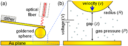
The experimental setup (Fig. 1) is a homemade atomic force microscope (AFM)
working at 300 K under controlled atmosphere. An optical-fiber based interferometric detection of
the cantilever Jourdan ; Siria provides the required sensitivity to measure the impact of gas
confinement on the viscous damping of the probe. The latter is a 460 m long, 50 m wide,
and 2 m thick, silicon AFM microlever with a m radius polystyrene sphere glued at
its extremity. In order to control the electrostatic interaction (see below), the whole probe (i.e.
cantilever and sphere) is coated with a 200 nm thick gold layer, and the AFM chip is glued with
silver paint on a holder attached to the microscope frame. The probe spring constant N/m
and the resonance frequency Hz have been measured using the Brownian motion of the
thermally actuated lever at 300 K Siria ; Drezet . The planar surface facing the sphere is a
silicon substrate coated with a 200 nm thick gold layer and mounted on a high-precision
positioning system to adjust the cavity gap between the sphere and the sample. An inertial
motor makes sub-micron steps over a large 7 mm displacement range, whereas a piezo-scanner
corrected for hysteresis distortions ensures a fine vertical positioning over a 1.5 m range.
For our measurements, it is important to conceive a method for measuring the absolute gap
. This is achieved by applying a voltage bias to the probe with respect to the facing flat
surface as commonly done in Casimir force measurements where contact between facing surfaces must
be avoided Jourdan ; deMan . The cantilever is mechanically actuated with a dither at its
resonant frequency using a phase-locked loop device and the resonant frequency shift is recorded as a function of to extract the coefficient that
bears the desired distance information ( is the difference in materials work functions). For
in the sphere-plane geometry, we use the relation to find the absolute distance . In fact, to reach a better precision of 2% on , we
record during a precise 1.5 m scan around the mean position and fit the results
against the above formula.
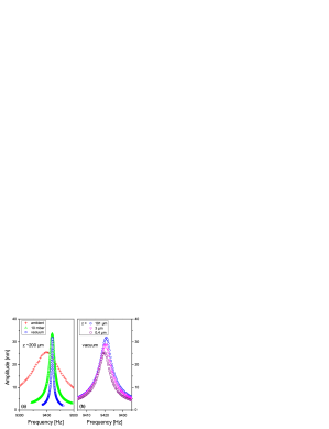
We have measured the vibration amplitude as function of the excitation frequency for three gas pressures and several distances . Examples of resonance curves are shown in Fig. 2(a) at large distance and for different pressures and in Fig. 2(b) for different distances in a primary vacuum. By fitting each curve with the Lorentzian response of an harmonic oscillator:
| (1) |
we obtain the dissipation constant of the probe, with a fitting error
smaller than 1%. The results are shown on the left graphs of Fig. 3 for three pressure
conditions: (a) air at atmospheric pressure (1000 mbar), (b) helium at low
pressure (10 mbar), and (c) air vacuum ( mbar).
When the sphere is far from the sample, the damping factor reaches a constant value
, characterizing the dissipation of the {cantilever + sphere} oscillating system in the
fluid. This value is directly extracted from the data and reported in Table 1 (except in
vacuum where the damping factor is not saturated at the largest distance and was
obtained by fitting with Eq. 3 as described below). As is also visible in
Fig. 2(a), decreases with decreasing pressure in agreement with previous
works Verbridge ; Li ; Svittelskiy . In the viscous regime this is mainly due to the existence of
a boundary layer of thickness Batchelor ; noteb representing a
dissipation channel at finite frequency that adds to the intrinsic losses
of the lever (i.e. losses in the limit ):
Verbridge ; Li ; Svittelskiy .
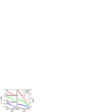
When the gap decreases, the hydrodynamic force due to the gas confinement contributes a
-dependent additional dissipation channel such that
. The central result of our work is shown in Fig. 3(d)
where is plotted for different pressures. It is clearly
seen that the dissipation observed at small distance is strongly reduced at low pressure. If in
agreement with usual statistical mechanics Batchelor we accept that the fluid viscosity
does not depend on pressure (a reasonable assumption in the viscous regime) we can conclude
that the boundary conditions at the solid-fluid interface should strongly change with pressure. In
other words, the so-called slip-length , usually used to characterize the fluid flow at the
interface Lauga ; Neto ; Bocquet , varies by a large amount. is related to the fluid velocity
gradient at the solid surface by
(where is the tangential fluid velocity) and can equivalently be interpreted as the fictitious
depth below the surface where the no-slip boundary conditions would be satisfied.
| Gas | [mbar] | [kg/s] | [m] | [m] | |
|---|---|---|---|---|---|
| Air | 1000 | 0.05 | 0.06 | 0.9 | |
| He | 10 | 70 | 10 | 0.17 | |
| Air | 0.04 | 1200 | 2500 | 1.2 |
In the sphere-plane geometry with no-slip boundary conditions (i.e. ), the dissipation constant is given in the limit by the Taylor formula Batchelor ; Neto :
| (2) |
where is the dynamic viscosity which does not change with pressure ( kg.m-1.s-1 for air and kg.m-1.s-1 for Helium). To take into account the gas slippage at the boundaries, we follow the reasoning of Hocking Hocking and Vinogradova Vinogradova1 and introduce a correction function such that
| (3) |
with . In this
formula (obtained for an incompressible fluid in the laminar regime note ) we assume the same
values for on both surfaces since the two walls are coated with the same material. By fitting
the three sets of data in Fig. 3(d) with Eq. 3 in the range m,
we determine a slip length for each pressure. Note that is the only free parameter in the
fit, except for the data in vacuum where both and are simultaneous adjustable
parameters. is however not sensitive to the choice of since is determined
essentially by the absolute changes of . The results are presented in Table 1
with an estimation of the error shown in Fig. 3(d). The strong increase of at lower
pressure clearly shows that the friction of the confined fluid along the solid boundaries
considerably changes with pressure going from the usual no-slip condition in ambient air (i.e.
follows a law) to a quasi-perfect slip regime at low gas
pressure (i.e. ).
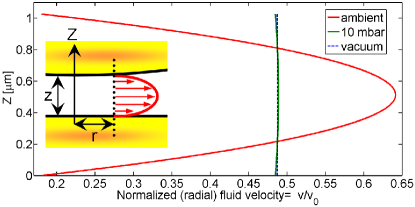
In order to visualize the impact of a finite on the fluid dynamics close to the
surface, we compute the (radial) fluid velocity profile in the gap between the two
surfaces using the analytical theory of Hocking ; Vinogradova1 . Due to the fluid
incompressibility and the limit , the fluid is essentially ejected from the gap in the
radial direction in response to the vertical displacement of the sphere notenote . The
comparison between the three different values of obtained in the experiment (see
Table 1) is shown in Fig. 4. We clearly switch from the usual Poiseuille
parabolic velocity profile (i.e. on the solid boundary) for , to a
quasi-constant velocity profile in the gap for . Therefore our experiment
reveals a continuous transition between these extreme regimes.
Now, from a microscopic point of view, the slippage coefficient is linked to the very nature of the interaction between moving surfaces and air molecules. Following the historical approach of Maxwell’s kinetic theory of gases Maxwell , two interaction channels can be distinguished: a specular one where molecules collide elastically with the surface and a diffusive one where molecules are reflected diffusively by the wall. The slip length in this statistical model is given by the Maxwell formula Maxwell ; Drezet ; Sharipov ; Fichman :
| (4) |
where is the typical mean free-path of gas molecules and the tangential momentum
accommodation coefficient, i.e. the fraction of those particles hitting the surface with a
diffusive reflection.
The main dependence of with pressure comes from the molecular mean free-path (see
Table 1): where is the temperature,
the Boltzmann’s constant, and the molecular cross-section. Two important asymptotic
regimes are clearly found in the experiment (see Fig. 4). On the one hand, when the
mean free-path is extremely small compared to other macroscopic dimensions (i.e. at ambient air
pressure), the fluid particles interact strongly with themselves, and even more strongly with
surfaces located within a characteristic distance given by . This is a consequence of
multiple collisions, reflections, and adsorption processes Maxwell ; Tabeling ; Lauga ; Bocquet .
In this diffusive regime, the tangential velocity of the molecules decreases at short distance from
the surface, such that the slip-length tends to zero and the no-slip condition applies. On the
other hand, when the mean free-path is considerably larger than the gap, the molecules interact
mainly with surfaces and there is no momentum transfer among the molecules themselves. In this
ballistic or molecular flow regime, the velocity gradient vanishes at the surface. This results
in a giant slip length .
In Eq. 4, the accommodation coefficient (see Table 1) depends
on the surface properties and gas density (i.e. on the probability of multiple collisions). Recent
analysis based on the fluctuation-dissipation theorem and the Green-Kubo relation emphasize the
importance of several microscopic parameters such as surface roughness and surface defects on the
molecular dynamics close to the surface Lauga ; Bocquet ; MicroNanoFluid ; Neto . In our experiment, the rms
roughness of the gold surfaces was found by AFM to be nm for both the sphere
and sample. This certainly contributes to increase and reduce as compared to a perfect surface.
Note that Eq. 3 is an analytical solution of the Navier-Stokes equations whose
validity is well established when the fluid density is sufficiently large to provide a local
equilibrium within the fluid. However, in the present experiment in vacuum, the mean free-path
is much larger than any other relevant length (e.g. the gap ) so that the system
enters in a molecular flow regime which should be discussed within the more general frame of
Boltzmann’s kinetic equations Batchelor ; Tabeling . Therefore, the slip length deduced
from our data at low pressure should be considered as an extrapolation showing the limitation of
the usual hydrodynamic approach. Because the low-pressure data of Fig. 3 are well
reproduced in our analysis, our work stresses the remarkable robustness of the
Navier-Stokes Eq. 3 even in this molecular regime.
Finally, it is worth commenting on the differences between the present sphere-plane
experiment and recent results obtained in a plane-plane geometry Siria . At atmospheric
pressure, we obtain here a small slip length in agreement with Refs. Maali ; deMan whereas
Ref. Siria reports on a perfect slip in the same fluid (air). One of the difference is the
geometry, which is indeed known to be a critical parameter at micro- and nanoscales
Tabeling ; Lauga ; Li ; Drezet ; Siria2 . Another difference in Ref. Siria is the probe
velocity which resulted from the thermal motion of the cantilever with oscillation amplitude
nm, whereas the probe is here mechanically actuated i.e. nm (in the
same context compare Refs.Honig and Maali ). In addition, the surface roughness was
only a few Angstroms, resulting in a smaller accommodation coefficient and a larger slip-length .
In conclusion, we have discovered that the slippage of a gas along mobile rigid walls
varies considerably with pressure in the sphere-plane confined geometry. The classical no-slip
boundary condition valid at ambient pressure changes continuously to an almost perfect slip
condition in vacuum. This study emphasizes the key role played by the mean free-path on
the interaction between a fluid and solid surfaces and demonstrates that the macroscopic hydrodynamics
approach can be used with confidence even in good vacuum conditions. We anticipate that our work will
have an impact on the MEMS and NEMS engineering and will motivate further fundamental studies of the
physics of gas slippage along solid and mobile surfaces.
We are grateful to K. Joulain and O. Arcizet for helpful discussions and to A. Mosset and
J. -F. Motte for valuable assistance during the experiments. This research was supported by the
PNANO 2006 program of the Agence Nationale de la Recherche under the project name “MONACO”.
References
- (1) G. K. Batchelor, Fluid dynamics, (Cambridge University Press, Cambridge (UK) 1974).
- (2) P. Tabeling, Introduction to microfluidics (Oxford University Press, USA, 2006).
- (3) E. Lauga, in Handbook of Experimental Fluid Dynamics edited by J. Foss, C. Tropea, and A. Yarin (Springer, New York, 2007), Chap. 19, p. 1219-1240.
- (4) L. Bocquet and E. Charlaix, Chem. Soc. Rev. 39, 1073 (2010).
- (5) S. Guriyanova, B. Semin, T.S Rodrigues, H.-J. Butt, and E. Bonaccurso, Microfluid. Nanofluid. 8, 653 (2010).
- (6) C. Neto, D. R. Evans, E. Bonaccurso, H.-J. Butt, and V. S. J. Craig, Rep. Prog. Phys. 68, 2859 (2005).
- (7) O. I. Vinogradova and G. E. Yakubov, Phys. Rev. E 73, 045302 (2006).
- (8) A. Maali and B. Bhushan, Phys. Rev. E 78, 027302 (2008).
- (9) S. S. Verbridge, R. Ilic, H. G. Craighead, and J. M. Parpia, Appl. Phys. Lett. 93, 013101 (2008).
- (10) M. Li, H. X. Tang, and M. L. Roukes, Nat. Nanotechnol 2, 114 (2007).
- (11) O. Svitelskiy, V. Sauer, N. Liu, K.-M. Cheng, E. Finley, M. R. Freeman, and W. K. Hiebert, Phys. Rev. Lett 103, 244501 (2009).
- (12) A. Siria, A. Drezet, F. Marchi, F. Comin, S. Huant, and J. Chevrier, Phys. Rev. Lett 102, 254503 (2009).
- (13) C.D.F. Honig and W. A. Ducker, J. Phys. Chem. C, 114 20114 (2010)
- (14) A. Drezet, A. Siria, S. Huant, and J. Chevrier, Phys. Rev. E 81, 046315 (2010).
- (15) G. Jourdan, A. Lambrecht, F. Comin, and J. Chevrier, Europhys. Lett. 85, 31001 (2009).
- (16) S. de Man, K. Heeck, R. J. Wijngaarden, and D. Iannuzzi, Phys. Rev. Lett. 103, 040402 (2009).
- (17) The boundary layer , where is kinematic viscosity Batchelor , is typically 20 m at ambient pressure and reaches a few mm in vacuum.
- (18) L. M. Hocking, J. Eng. Math. 7, 207 (1973).
- (19) O. Vinogradova, Langmuir 11, 2213 (1995).
- (20) A typical value for the Reynolds number in our experiments is at ambient pressure. At lower pressure this number is even reduced proportionally to pressure. This justifies our assumption of a laminar regime. Similarly, the gas incompressibility hypothesis is fully justified since the Mach number ( is sound velocity) is very small.
- (21) Here we have applied the Taylor formula (Eq. 2 and its extension Eq. 3) to values exceeding the sphere radius although it is valid in the limit only, so that our approach reveals general trends at large distances, rather than offering an accurate quantitative analysis. Similarly, the small tilt angle () of the vibrating cantilever with respect to the plane surface (Fig. 1) results in a small horizontal velocity (18% of the main vertical velocity) that we neglect, but this does not change the orders of magnitude discussed here.
- (22) J. C. Maxwell, Philos. Trans. R. Soc. London, Ser. B 170, 231 (1879).
- (23) F. Sharipov and D. Kalempa, Phys. Fluids 15, 1800 (2003).
- (24) M. Fichman and G. Hetsroni, Phys. Fluids 17, 123102 (2005).
- (25) A. Siria, S. Huant, G. Auvert, F. Comin and J. Chevrier, Nanoscale Res. Lett. 5, 1360 (2010).