Simulations of Bunch Merging in a Beta Beam Decay Ring
Abstract
To further study neutrino oscillation properties a Beta Beam facility has been proposed. Beta decaying ions with high kinetic energy are stored in a storage ring (”Decay Ring”) with straight sections to create pure focused (anti) electron neutrino beams. However to reach high sensitivity to neutrino oscillation parameters in the experiment the bunched beam intensity and duty cycle in the DR have to be optimized. The first CERN-based scenario, using 6He and 18Ne as neutrino sources, has been studied using a bunch merging RF scheme. Two RF cavities at different frequencies are used to capture newly injected bunches and then merge them into the stored bunches. It was shown that this scheme could satisfy the requirements on intensity and duty cycle set by the experiment. This merging scheme has now been revised with new simulation software providing new results for 6He and 18Ne. Furthermore bunch merging has been studied for the second CERN-based scenario using 8Li and 8B.
Keywords:
Beta Beams, Decay Ring, Merging, EUROnu-WP4-0121 Introduction
Improving the measurements of the known neutrino oscillation parameters (like , , and ) and determination of the unknown ones (like , sign and ) requires precision measurements on a highly pure and intense neutrino beam whose characteristics are well known. One of the proposed next generation neutrino oscillation facilities FP7 (2007) is the Beta Beam concept Zucchelli (2002). Beta decaying ions are stored at in a horse-racetrack shaped storage ring, the "Decay Ring". One of the straight sections is aimed at an oscillation experiment and the decaying ions create a highly pure (anti) electron neutrino beam with an opening angle of .
Within the EURISOL design study (FP6 EC (????a)) the feasibility of a scenario using 6He (as antineutrino source) and 18Ne (as neutrino source) isotopes has been investigated. A 440kt Čerenkov detector located in the Fr jus tunnel at km distance from CERN was foreseen to detect the incoming neutrinos. The proposed method for bunch injection in the Decay Ring (DR), the so called "RF bunch merging scheme", creates bunches with sufficient intensity while keeping the duty cycle (which coincides with the suppression factor of the experiment) of the DR at and well below the sensitivity threshold of 1% given within FP6.
The EUROnu design study (FP7 EC (????b)) includes an additional scenario using 8B (as neutrino source) and 8Li (as antineutrino source) isotopes. Since these isotopes feature a higher Q value, the neutrino energies will be higher and a longer baseline between production and detection is needed. The detector can be placed in Gran Sasso ( km) or Canfranc ( km). A new RF scheme called "barrier buckets" was proposed but simulations showed that an optimization between bunched intensity and duty cycle could not be achieved Hansen et al. (2010). This report therefore focuses on the adaptation of the RF bunch merging scheme used in the EURISOL design study to the isotopes used within EUROnu
Both baselines assume the Beta Beam accelerator complex to be located at CERN, reusing the existing PS and SPS, and that the DR has the same circumference as SPS, namely 6911 m.
2 RF Simulations
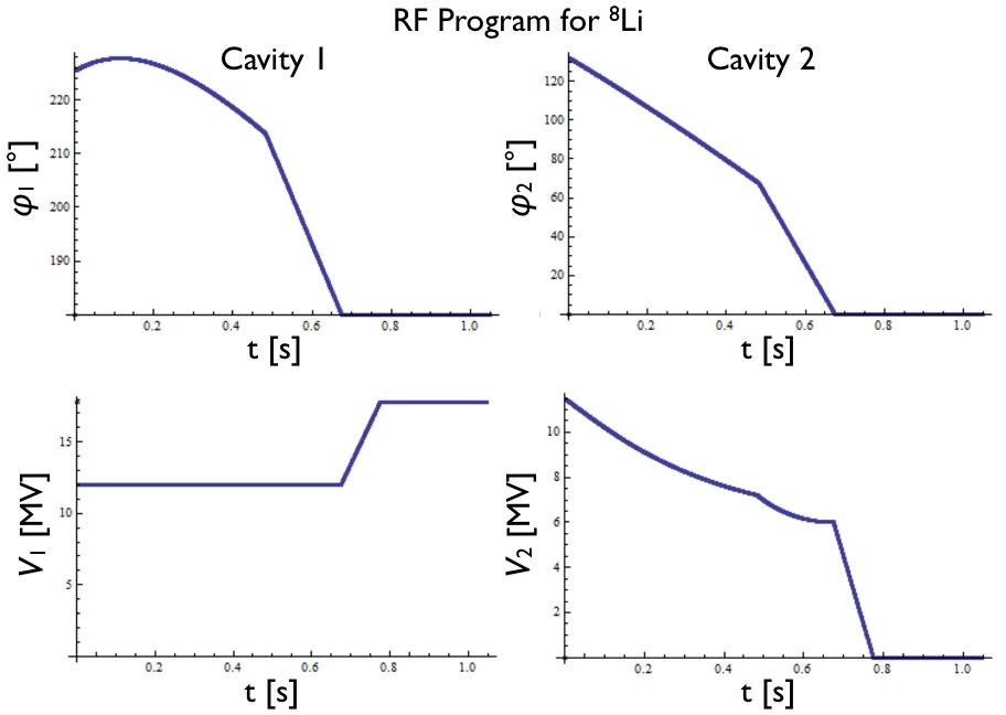
The RF simulations are done by using the 2D longitudinal phase space program ”BBPhase” Christian Hansen, Daniel Heinrich (????) written to investigate the possibility to use Barrier Buckets in the Decay Ring Hansen et al. (2010). It has since been adapted to perform Bunch Merging simulations. The program tracks the particles on a turn-by-turn basis. After each turn the particles’ phases and momenta are evaluated dependent on the voltage they have seen from the RF system in the previous turn. The combined voltage from two cavities with frequencies MHz () and MHz (), is
| (1) |
where the (time dependent) maximum voltages are , the RF phase when a reference particle passes through the long wavelength RF cavity is and when it passes through the fast frequency RF cavity and is the azimuthal difference between the reference particle and a given particle in the bunch.
The merging program was theoretically optimized for 6He and 18Ne Chanc et al. (????) and has now been adapted for 8Li and 8B. The plots in fig. 1 represent the changes in phases and voltages for the merging program of Lithium.
We apply the merging program (fig. 1) of Lithium to the case that one bunch is already injected and circulating in the main bucket (black dots in fig. 2 represent multiparticles of this bunch). The newly injected beam (red) is distributed in a longitudinal phase space ellipse at a momentum excess of per mil (fig. 2a). The best capture efficiency could be obtained by slightly lowering the particles momentum excess to per mil and moving it about cm behind the stored bunch. The particles perform a quarter synchrotron turn and loose their elliptical distribution since the movement around the synchronous particle is not linear in this region of phase space (fig. 2b). This causes some particles to be outside the elliptical shaped capture bucket when the second cavity is turned on. Those particles are not captured and circle on the separatrix around both buckets. Asymmetric merging is applied during 0.5 seconds where the main bucket shrinks in size (until both buckets have the same size, fig. 2c, 2d and 2e). After that the symmetric merging procedure takes about seconds to decrease the distance between the two buckets to zero (fig. 2f and 2g). At this point the second cavity is turned off and the main RF is progressively tuned to nominal voltage. Before the next injection the particles circulating around the bucket have to be collimated at per mil momentum excess (fig. 2h) or they will hit the septum blade during the next injection.
These simulations have been done with all FP6 and FP7 ions together with capture efficiency studies. Capture efficiency is defined as quotient between not-collimated (e.g. running or decayed) particles and injected particles at the end of each SPS cycle. It was possible to reach an efficiency of slightly below 90% in all cases (table 1). However the results for 8Li and 8B are very preliminary since no data on longitudinal emittances was available at the time of the simulations.
| 6He | 18Ne | 8Li | 8B | |
| at rest [ms] | 807 | 1872 | 838 | 770 |
| SPS cycle time [s] | 6.0 | 3.6 | 4.8 | 3.6 |
| Source rate [1013/s] | 2 | 2.09 | 9 | 9 |
| Inject./Bunch [1011] | 4.87 | 2.35 | 21.50 | 8.43 |
| Capture Efficiency | 88.8% | 87.8% | 88.2% | 89.0% |
| Acc./Bunch [1011] | 40 | 31 | 173 | 74 |
| Acc. in DR [1013] | 8 | 6.20 | 35 | 13.6 |
| -rate [1018/year] | 2.4 | 0.92 | 10.2 | 4.34 |
| Nom. -rate [1018] | 2.9 | 1.1 | 14.5 | 5.5 |
| -rate ratio | 0.828 | 0.836 | 0.705 | 0.788 |
During the merging process the longitudinal emittance of the stored beam is increased due to RF gymnastics. The collimation at per mil momentum excess will therefore limit the bunch size after a certain number of injections. Together with radioactive decay (also included in the BBPhase simulation) the collimation will therefore cause the accumulated number of ions in the bunch to saturate. We obtain the number of particles after which a bunch is saturated by repeatedly applying the merging program with the appropriate cycle times for each ion (table 1). The amount of remaining particles per bunch is plotted every turns over a period of injections ( for 18Ne due to later saturation of Neon) in figure 3. Due to uncertainties in the ion production (R&D is ongoing) the amount of injected ions per cycle is an estimated value for all isotopes.
At saturation the size of one stored bunch is about 2 meters for all ions. The duty cycle of the DR ( = suppression factor of the experiment), assuming 20 injected bunches, is then . This holds for all tested ions which is in agreement with the results in Chanc et al. (????) and extends them to 8Li and 8B. From the number of accumulated ions and 20 injected bunches we can calculate the annual neutrino flux via a Mathematica notebook Wildner et al. (????). It turns out that the amount of ions stored at saturation (Ne per bunch and He per bunch) corresponds to only () of the nominal (anti) neutrino flux Beta Beam Study Group (2009) (see table 1). In the case of 8Li and 8B sensitivity plots shows that nominal neutrino rate needed is 5 times larger than for 6He and 18Ne Fernandez-Martinez (2010). The (anti) neutrino flux achieved from the number of ions stored in the DR at saturation corresponds to (8Li) and (8B) of the nominal fluxes.
We are however well below the requirements of the duty cycle which is at maximum .
3 Conclusions
It was possible to adapt the radio frequency bunch merging scheme to the 2D program BBPhase and recreate the capture efficiencies already calculated in case of FP6 ions Chanc et al. (????). These results could also be extended to 8Li and 8B using preliminary values for emittances and ion production showing the feasibility of bunch merging for these isotopes. Moreover the duty factor considering 20 accumulated bunches in the Decay Ring was found to be 0.58% which also agrees with the previous theoretical results and is well below the upper limit of . In light of these results the Bunch Merging procedure is at present the preferred method to create ion bunches with a sufficiently low duty cycle inside the Decay Ring.
However the amount of ions that could be stored in one bunch at saturation was found to be lower than needed for the production of nominal (anti) neutrino flux in the Helium and Neon case. For the Lithium and Boron case further R&D is needed in terms of ion production and transportation. The simulations will then have to be repeated with new values for longitudinal emittances and injected bunch intensities.
References
- FP7 (2007) (2007), FP7-INFRASTRUCTURES-2007-1.
- Zucchelli (2002) P. Zucchelli, Phys. Lett. B532, 166–172, (2002).
- EC (????a) EC http://cordis.europa.eu/fp6.
- EC (????b) EC http://cordis.europa.eu/fp7.
- Hansen et al. (2010) C. Hansen, E. Wildner, and E. F. Martinez, AIP Conference Proceedings 1222, 455–458, (2010), URL http://link.aip.org/link/?APC/1222/455/1.
- Christian Hansen, Daniel Heinrich (????) Christian Hansen, Daniel Heinrich, BBPhase, http://svnweb.cern.ch/world/wsvn/bbphase/.
- Chanc et al. (????) A. Chanc , et al. 12-25-2009-0019.
- Fernandez-Martinez (2010) E. Fernandez-Martinez, Nucl. Phys. B833, 96–107, (2010), 0912.3804.
- Wildner et al. (????) E. Wildner, et al. CERN-AB-2007-015.
- Beta Beam Study Group (2009) Beta Beam Study Group (2009), URL http://beta-beam.web.cern.ch/beta-beam/task/Final\%20report/F%inalreport.asp.