Collective Effect Studies of a Beta Beam Decay Ring
Abstract
The Beta Beam, the concept of generating a pure and intense (anti) neutrino beam by letting accelerated radioactive ions beta decay in a storage ring called the Decay Ring (DR), is the basis of one of the proposed next generation neutrino oscillation facilities, necessary for a complete study of the neutrino oscillation parameter space. Sensitivities of the unknown neutrino oscillation parameters depend on the DR’s ion intensity and of its duty factor (the filled ratio of the ring). Different methods, including analytical calculations and multiparticle tracking simulations, were used to estimate the DR’s potential to contain enough ions in as small a part of the ring as needed for the sensitivities. Studies of transverse blow up of the beams due to resonance wake fields show that a very challenging upper limit of the transverse broadband impedance is required to avoid instabilities and beam loss.
Keywords:
Neutrino Oscillation, Beta Beams, Decay Ring, Collective Effects, Impedance:
1 Introduction
The discovery of neutrino oscillations Fukuda et al. (1998) has confirmed that neutrinos are massive and that their flavor (, , ) and mass eigenstates (, , ) are mixed. Neutrino physics is now in an era of precision measurements of the parameters that govern these oscillations: two parameters (, ), three mixing angles (, , ) and a CP violating phase (). The most precise determinations to date are eV2, Yang et al. (2009), eV2 Adamson et al. (2008) and ISHIHARA (2009).
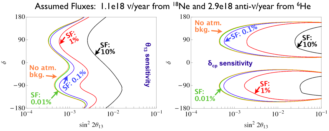
This leaves three unknowns: (¡ Apollonio et al. (2003)), and sign(). The discovery of and and would mean existence of CP violation in the leptonic sector. Near future experiments will perform precision measurements of the knowns and continue to probe the unknowns (e.g. T2K started taking data 2009 Ichikawa (2010)). However, a complete study of all neutrino parameters requires a better characterized neutrino beam with higher flux then ever available before. One of the three present options for a next generation neutrino oscillation facility The Commission of the European Communities (2007) is the Beta Beam concept Zucchelli (2002) wherein it is proposed to store high energy ( = 100) radioactive ions in a horse-track shaped storage ring, called “Decay Ring” (DR), with a straight section pointing to a neutrino detector. Ions that beta-decay in the straight section emit electron (anti) neutrinos in a pure () beam with opening angle . The aimed annual (anti) neutrino fluxes of (1.1e18) 2.9e18 Beta Beam Study Group (????) from () decaying (6He) 18Ne ions give and sensitivities shown in fig. 1 Fernandez-Martinez (2010) for different suppression factors (SF) of the detector (which coincides with the duty factor of the DR). Fig. 1 shows that with the nominal fluxes the beam can only fill less than 1% of the DR. The challenges of how to produce enough ions, how to accelerate them through a Beta Beam complex and how to achieve 0.58% SF are described elsewhere Beta Beam Study Group (????). In the studied scenario the Beta Beam complex is based at CERN, making use of already existing PS and SPS machines and the DR has the same circumference as SPS, = 6911.6 m. Assuming 20 bunches of 6911.6m0.58%/20 = 2 m each, the number of 18Ne (6He) per bunch have to be () to reach the nominal (anti) neutrino fluxes. In this report we focus on the question whether the required amount of ions can populate such short bunches without too large a risk of beam instabilities. This collective effect study is based on the previous design studies Beta Beam Study Group (????) and all parameters used are listed in table 1 and 2.
| Parameters | DR 18Ne | DR 6He |
|---|---|---|
| 10 | 2 | |
| 18 | 6 | |
| [MV] | 11.96 | 20.00 |
| [MeV] | 16767.10 | 5605.54 |
| 3.1e+12 | 4.0e+12 | |
| [s] | 1.67 | 0.81 |
| [s] | 3.60 | 6.00 |
| [m] | 8.53e-18 | 1.02e-18 |
| [GeV] | 1676.71 | 560.55 |
| [A] | 755.80 | 195.04 |
| [A] | 0.22 | 0.06 |
| [eVs] | 43.27 | 14.46 |
| Parameters | Description | Value |
|---|---|---|
| Harmonic Number | 924 | |
| [m] | Circumference | 6911.6 |
| [m] | Magnetic Radius | 155.6 |
| Gamma at Transition | 27.00 | |
| Relativistic Gamma | 100.0 | |
| Max. Mom. Spread | 2.5e-3 | |
| [m] | Full Bunch Length | 1.970 |
| Vertical Tune | 12.16 | |
| [m] | Av. Ver. tron Func. | 173.64 |
| [cm] | Ver. Beam Pipe Size | 16.0 |
| Quality Factor | 1.00 | |
| [GHz] | Ang. Resonance Freq. | 6.28 |
| Shunt Impedance | 2.00 | |
| Phase Slip Factor | 1.27e-3 | |
| [ s] | Revolution Time | 23.0558 |
| [MHz] | Ang. Revolution Freq. | 0.27 |
| Synchrotron Tune | 3.63e-3 | |
| [GHz] | Cut-Off Ang. Frequency | 1.87 |
2 Collective Effect Studies
High intensity ion beams, foreseen for the Beta Beam project, could suffer “Collective Effects”. These are caused by electromagnetic interactions between particles in the beam, either with each other directly or through the surrounding environment. Collective effects could limit the final performance of the accelerators. The studies of instabilities of all ion beams and all machines in the Beta Beam complex is therefore a crucial part of the project. Here we have focused on 18Ne and 6He in the DR.
A particle traveling inside an accelerator leaves electromagnetic fields lagging behind. Trailing particles feel a force due to the net field caused by all preceding particles. The line integral of this force over a certain length (which could be a part of the beam chamber) gives what the particles see as ”wake fields”. If the wake fields last for the duration of the bunch (100 ps) particles in the “tail” of the bunch can interact with the wake fields caused by the particles in the “head” of the bunch and cause single bunch instabilities.
The action of the wake fields are described by the wake potential, , in the time domain and by the impedance, , in the frequency domain. This report studies impedances caused by wake fields trapped in cavities of the vacuum chamber, so called resonance impedances, . If the quality factor is = and the resonance frequency is = the resonance impedance can be modelled as an RLC circuit Chin (????a) in the transverse plane as
| (1) |
where is the transverse shunt impedance, assumed to have a value close to RHIC; 2 M/m Fischer et al. (????). So far we have only studied short lived resonance wake fields, i.e. broadband ( = 1) impedances in the transverse plane. There are many different types of collective effects that could lead to beam instability but this study is constrained to transverse broadband resonance impedances. Three different methods have been used to achieve the maximum number of allowed ions per bunch, .
One approach is to use the peak current values of the bunch current and momentum spread as input to a coasting beam formula. This gives an expression for the intensity limit that we will call the coasting beam equation Metral (????) and which for zero chromaticity (as assumed all through this report) is
| (2) |
Here is the speed of light in vacuum and all other parameters are given in table 1 and 2.
MOSES Chin (????b) solves an integral equation in the frequency domain to give the rise time, , of the instabilities for different head-tail modes as a function of the bunch intensity. The limit, , is given by the most crucial head-tail mode after defining the maximum allowed growth rate, . To reach the ion equivalent intensity threshold we divide by a factor ; . The maximum allowed number of ions per bunch is then given by the conversion = .
The third method uses the multiparticle tracking code HEADTAILRumolo, Giovanni et al (????) where a bunch of macro-particles is sliced longitudinally and the impedance is assumed to be localized at a few positions around the ring. At each impedance location, each slice leaves a wake field behind and gets a kick by the field generated by the preceding slices. The bunch is then transferred to the next impedance location via a transport matrix. For the Beta Beam studies the possibility of bunches with 18Ne and 6He was added to the code. An exponential least squared fit to the envelope of the vertical oscillation of the mean bunch position gives the growth rate of the instability. Same as for MOSES the bunch intensity limit, , is reached when the rise time is shorter than allowed, i.e. .
It could be argued that instabilities with the longest rise times should define , i.e. . However in this report we will take an optimistic approach, assume that slow instabilities can be damped with sextu- and octupoles and define for both MOSES and HEADTAIL.
With the three methods, mentioned above, we studied the effect on the bunch intensity limit, , by changing slightly the longitudinal emittance, , (fig. 2 (a) and (b)) and assuming = 2 M/m. Fig. 2 (a) shows that according to MOSES (HEADTAIL) increasing with about 5 (10) eVs from the working point (indicated by grey arrow) the desired number 6He per bunch, , would be acceptable. This would however also mean an undesired increase in SF and momentum spread (also indicated in fig. 2 (a)). As can be seen in fig. 2 (b) the bunch intensity limit for 18Ne, , is far out of reach when = 2 M/m is assumed.
Since impedance could improve in modern machines compared to old accelerators a scan over the shunt impedance was performed to see the impact on (fig. 2 (c) and (d)). Fig. 2 (c) shows that for a shunt impedance at the level of SPS, = 20 M/m, maximum number 6He allowed per bunch, according to HEADTAIL and MOSES, is not more than 300. For = 6He per bunch 2 M/m (similar to RHIC) is needed. However, as can be seen in the log-log scale plot of fig. 2 (d) 0.2 M/m is needed in the DR to allow 18Ne per bunch.
Scans over resonance frequency, , and chromaticity, , were also performed without any significant relaxation in bunch intensity limit, , within realistic ranges of the scan parameters.
3 Conclusions
There will be large challenges due to requirements of seemingly insurmountable low transverse broadband impedance of the Beta Beam Decay Ring. This study, based on parameters mostly from Beta Beam Study Group (????) (table 1 and 2), suggests a reoptimization of the Beta Beam Decay Ring design.
References
- Fukuda et al. (1998) Y. Fukuda, et al., Phys. Rev. Lett. 81, 1562–1567, (1998), hep-ex/9807003.
- Yang et al. (2009) P. Yang, et al., Chin. Phys. Lett. 26, 031401, (2009).
- Adamson et al. (2008) P. Adamson, et al., Phys. Rev. Lett. 101, 131802, (2008), 0806.2237.
- ISHIHARA (2009) C. ISHIHARA, Proceedings of the 31st ICRC (2009).
- Fernandez-Martinez (2010) E. Fernandez-Martinez, Nucl. Phys. B833, 96–107, (2010), %****␣bbCollective.bbl␣Line␣25␣****0912.3804.
- Apollonio et al. (2003) M. Apollonio, et al., Eur. Phys. J. C27, 331–374, (2003), hep-ex/0301017.
- Ichikawa (2010) A. K. Ichikawa, J. Phys. Conf. Ser. 203, 012104, (2010).
- The Commission of the European Communities (2007) The Commission of the European Communities (2007), FP7-INFRASTRUCTURES-2007-1.
- Zucchelli (2002) P. Zucchelli, Phys. Lett. B532, 166–172, (2002).
- Beta Beam Study Group (????) Beta Beam Study Group URL http://beta-beam.web.cern.ch/beta-beam/task/Final\%20report/F%inalreport.asp.
- Chin (????a) Y. H. Chin Proceedings of the 8th Joint School on Accelerator Physics, 1998.
- Fischer et al. (????) W. Fischer, et al. EPAC’08, 11th European Particle Accelerator Conference, 23- 27 June 2008, Genoa, Italy.
- Metral (????) E. Metral Prepared for 1st CARE-HHH-APD, Geneva, 8-11 Nov 2004.
- Chin (????b) Y. H. Chin CERN-LEP-TH/88-05.
- Rumolo, Giovanni et al (????) Rumolo, Giovanni et al CERN-SL-Note-2002-036-AP.