Generation and Characterization of Electron Bunches with Ramped
Current Profiles in a Dual-Frequency Superconducting Linear Accelerator
Abstract
We report on the successful experimental generation of electron bunches with ramped current profiles. The technique relies on impressing nonlinear correlations in the longitudinal phase space using a superconducing radiofrequency linear accelerator operating at two frequencies and a current-enhancing dispersive section. The produced -MeV bunches have peak currents of the order of a kilo-Ampère. Data taken for various accelerator settings demonstrate the versatility of the method and in particular its ability to produce current profiles that have a quasi-linear dependency on the longitudinal (temporal) coordinate. The measured bunch parameters are shown, via numerical simulations, to produce gigavolt-per-meter peak accelerating electric fields with transformer ratios larger than 2 in dielectric-lined waveguides.
pacs:
29.27.-a, 41.85.-p, 41.75.FrElectron acceleration is a rapidly-advancing field of scientific research with widespread applications in industry and medicine. Producing and accelerating high-quality electron bunches within very compact footprints is a challenging task that will most probably use advanced acceleration methods. These techniques can be categorized into laser-driven malka ; leemann ; varin and charged-particle-beam-driven methods pisin ; petra ; gai ; Caldwell . In the latter scheme, a popular configuration consists of a “drive” electron bunch with suitable parameters propagating through a high-impedance structure or plasma medium thereby inducing an electromagnetic wake. A following “witness” electron bunch, properly delayed, can be accelerated by these wakefields.
Collinear beam-driven acceleration techniques have demonstrated accelerating fields in excess of GV/m slac ; matt . The fundamental wakefield theorem wake limits the transformer ratio – the maximum accelerating wakefield over the decelerating field experienced by the driving bunch – to 2 for bunches with symmetric current profiles. Tailored bunches with asymmetric , e.g. a linearly-ramped, current profiles can lead to transformer ratio bane . To date, there has been a small number of techniques capable of producing linearly-ramped electron bunches. A successful experiment demonstrated the production of 50-A ramped electron bunches using sextupole magnets located in a dispersive section england to impart nonlinear correlation in the longitudinal phase space (LPS). Unfortunately, the method introduces coupling between the longitudinal and transverse degrees of freedom which ultimately affects the transverse brightness of the drive and witness bunches.
In this Letter we present an alternative technique that uses a radiofrequency (rf) linear accelerator (linac) operating at two frequencies. It has long been recognized that linacs operating at multiple frequencies could be used to correct for LPS distortions and improve the final peak current smith ; dowell . We show analytically and demonstrate experimentally how a two frequency linac could be operated to tailor the nonlinear correlations in the LPS thereby providing control over the current profile.
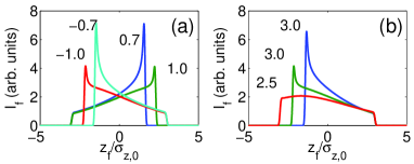
We first elaborate the proposed method using a 1D-1V single-particle model of the LPS dynamics and take an electron with coordinates where refers to the longitudinal position of the electron with respect to the bunch barycenter (in our convention corresponds to the head of the bunch) and is the fractional momentum spread ( is the electron’s momentum and the average momentum of the bunch). Considering a photo-emission electron source, the LPS coordinates downstream are where , and are constants that depend on the bunch charge and operating parameters of the electron source. For sake of simplicity we limit our model to second order in and . Next, we examine the acceleration through a linac operating at the frequencies and with total accelerating voltage where and are respectively the accelerating voltages and operating phases of the two linac sections, and . In our convention, when the phases between the linac sections and the electron bunch are the bunch energy gain is maximum (this is refer to as on-crest operation). Under the assumption and neglecting non-relativistic effects, the electron’s LPS coordinate downstream of the linac are where , with being the electronic charge and the beam’s average energy downstream of the linac. Finally, we study the passage of the bunch through an achromatic current-enhancing dispersive section [henceforth referred to as “bunch compressor” (BC)]. The LPS dynamics through a BC is approximated by the transformation where (also referred to as longitudinal dispersion), and are the coefficients of the Taylor expansion of the transfer map of the BC. Therefore the final position is given as function of the initial coordinates following with and . Taking the initial current to follow the Gaussian distribution (where is the initial peak current), and invoking the charge conservation gives the final current distribution where and is the Heaviside function. The latter current distribution does not include the effect of the initial uncorrelated fractional momentum spread . The final current, taking into account , is given by the convolution where . The final current shape is controlled via and and can be tailored to follow a linear ramp as demonstrated in Fig. 1.
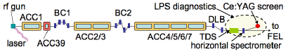
The experiment described in this Letter was performed at the Free-electron LASer in Hamburg (FLASH) facility flash . In the FLASH accelerator, diagrammed in Fig. 2, the electron bunches are generated via photoemission from a cesium telluride photocathode located on the back plate of a 1+1/2 cell normal-conducting rf cavity operating at 1.3 GHz on the TM010 -mode (rf gun). The bunch is then accelerated in a 1.3-GHz and 3.9-GHz superconducting accelerating modules (respectively ACC1 and ACC39) before passing through a bunch compressor (BC1). The ACC39 3rd-harmonic module was installed to nominally correct for nonlinear distortions in the LPS and enhance the final peak current of the electron bunch piot . Downstream of BC1, the bunch is accelerated and can be further compressed in BC2. A last acceleration stage (ACC4/5/6/7) brings the beam to its final energy (maximum of GeV). The beam’s direction is then horizontally translated using a dispersionless section referred to as dogleg beamline (DLB). Nominally, the beam is sent to a string of undulators to produce ultraviolet light via the self-amplified stimulated emission free-electron laser (FEL) process. For our experiment, the bunches were instead vertically sheared by a 2.856-GHz transverse deflecting structure (TDS) operating on the TM110-like mode and horizontally bent by a downstream spectrometer beherens . Consequently the transverse density measured on the downstream Cerium-doped Yttrium Aluminum Garnet (Ce:YAG) scintillating screen is representative of the LPS density distribution. The horizontal and vertical coordinates at the Ce:YAG screen are respectively , where m is the horizontal dispersion function, and where is the vertical shearing factor and refers to the LPS coordinate upstream of the TDS. The exact values of and are experimentally determined via a beam-based calibration procedure.
| parameter | symbol | value | unit |
|---|---|---|---|
| ACC1 voltage | [140-157] | MV | |
| ACC1 phase | [-10,10] | deg | |
| ACC39 voltage | [13,21] | MV | |
| ACC39 phase | [160-180] | deg | |
| ACC2/3 voltage | 311 | MV | |
| ACC2/3 phase | 0 | deg | |
| ACC4/5/6/7 voltage | 233.9 | MV | |
| ACC4/5/6/7 phase | 0 | deg | |
| BC1 longitudinal dispersion | mm | ||
| BC2 longitudinal dispersion | mm | ||
| Single-bunch charge | 0.5 | nC | |
| Bunch energy | MeV |
The accelerator parameters settings are gathered in Tab. 1. The nominal settings of BC2 were altered to reduce its longitudinal dispersion and the ACC2/3 and ACC4/5/6/7 accelerating modules were operated on crest. Such settings insure that the BC2 and the DBL sections do not significantly affect the LPS beam dynamics. Therefore the measured current profile is representative of the profile downstream of BC1.
In order to validate the simple analytical model described above, numerical simulations of the LPS beam dynamics were carried using a multi-particle model. The simulations also enable the investigation of possible detrimental effects resulting from collective effects such as longitudinal space charge (LSC) and beam self interaction via coherent synchrotron radiation (CSR) saldin . In these simulations, the beam dynamics in the rf-gun was modeled with the particle-in-cell program astra astra and the obtained distribution was subsequently tracked in the accelerating modules using a 1D-1V program that incorporates a one-dimensional model of the LSC. The program csrtrack csrtrack , which self-consistently simulates CSR effects, was used to model the beam dynamics in the BC1, and BC2 sections. An example of simulated LPS distributions and associated current profiles computed for different settings of ACC1 and ACC39 parameters appear in Fig. 3. The results indicate that the production ramped bunches is possible despite the intricate LPS structures developing due to the collective effects and higher-order nonlinear effects not included in our analytical model. The simulations also confirm that the current profile upstream of the TDS (as measured by the LPS diagnostics) is representative of the one downstream of BC1.
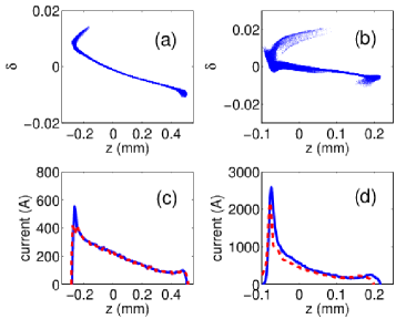
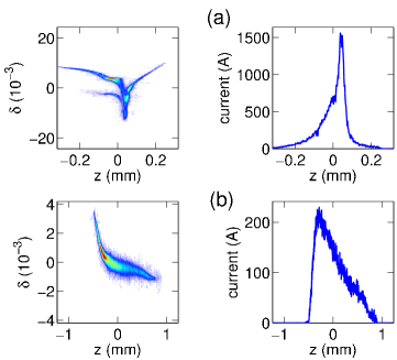
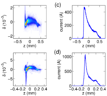
Figure 4 displays examples of measured LPS distributions with associated current profiles obtained for different settings of ACC1 and ACC39. As predicted, the observed current profiles are asymmetric and can be tailored to be ramped with the head of the bunch () having less charge than the tail; see Fig. 4 (b-d). The latter feature is in contrast with the nominal compression case at FLASH where the LPS distortion usually results in a low-charge trailing population as seen in Fig. 4 (a).
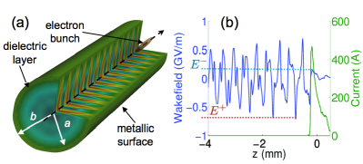
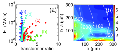
We now quantify the performance of the produced current profiles to enhance beam-driven acceleration techniques by considering a drive bunch injected in a cylindrical-symmetric dielectric-lined waveguide (DLW) gai . The DLW consists of a hollow dielectric cylinder with inner and outer radii and . The cylinder is taken to be diamond (relative electric permittivity ); and its outer surface is contacted with a perfect conductor; see Fig. 5 (a). The measured current profiles are numerically convolved with the Green’s function associated to the monopole mode to yield the axial electric field rosinggai . These semi-analytical calculations were benchmarked against finite-difference time-domain electromagnetic simulations executed with vorpal vorpal . The transformer ratio is numerically inferred as where (resp. ) is the decelerating (resp. accelerating) axial electric field within (resp. behind) the electron bunch; see Fig. 5 (b). The achieved and values as the structure geometry is varied are shown in Fig. 6. As m and m are varied the wavelengths of the excited wakefield modes change. The simulations show that profiles (b) and (c) of Fig. 4 can yield values of . A possible configuration with m, results in with GV/m; see corresponding wake in Fig. 5 (b). Such high-field with transformer ratio significantly higher than 2 and driven by bunches produced in a superconducting linac could pave the way toward compact high-repetition-rate short-wavelength FELs jing .
Finally, the proposed technique could be adapted to non-ultrarelativistic energies using a two- (or multi-) frequency version of the velocity-bunching scheme velo . Such an implementation would circumvent the use of a BC and would therefore be immune to CSR effects.
In summary we proposed and experimentally demonstrated a simple method for shaping the current profile of relativistic electron bunches. The technique could be further refined by, e.g., including several harmonic frequencies.
We are thankful to the FLASH team for the excellent technical support. We thank K. Flöttmann, T. Limberg, I. Zagorodnov, E. Vogel, S. Wesch, H. Edwards, B. Faatz, K. Honkavaara, and S. Schreiber for discussions and support. This work was sponsored by the DTRA award HDTRA1-10-1-0051 to Northern Illinois University, the German’s Bundesministerium für Bildung und Forschung and by the DOE contract DE-AC02-07CH11359 to the Fermi research alliance LLC.
References
- (1) T. Tajima, D. Dawson, Phys. Rev. Lett. 43, 267 (1979).
- (2) W. Leemann, et al., Nature Physics 2, 696 (2006).
- (3) C. Varin, M. Pich , and M. A. Porras, Phys. Rev. E 71, 026603 (2005).
- (4) P. Chen, J.M. Dawson, Robert W. Huff, T. Katsouleas, Phys. Rev. Lett. 54, 693 (1985).
- (5) G. A. Voss, and T. Weiland, “Particle acceleration by wakefields”, report DESY-M-82-10 available from DESY Hamburg (1982).
- (6) W. Gai, P. Schoessow , B. Cole, R. Konecny, J. Norem, J. Rosenzweig, and J. Simpson, Phys. Rev. Lett. 61, 2756 (1988).
- (7) A. Caldwell, K. Lotov, A. Pukhov, and F. Simon, Nature Physics 5, 363 (2009).
- (8) R. D. Ruth, A. Chao, P. L. Morton, P. B. Wilson, Part. Accel. 17, 171 (1985).
- (9) I. Blumenfeld, et al., Nature 445, 741 (2007).
- (10) M.C. Thompson, et al., Phys. Rev. Lett., 100, 21 (2008).
- (11) K. L. F. Bane, P. Chen, P. B. Wilson, “On collinear wakefield acceleration”, SLAC-PUB-3662 (1985).
- (12) R. J. England, J. B. Rosenzweig, and G. Travish, Phys. Rev. Lett. 100, 214802 (2008).
- (13) T. Smith, in Proceedings of the 1984 Linear Accelerator Conference (LINAC’84), SLAC report 303, 421 (1986).
- (14) D. H. Dowell, J. L. Adamski, T. D. Hayward, C. G. Parazzoli and A. M. Vetter, Nucl. Instrum. Meth. A375, 108 (1996).
- (15) W. Ackermann, et al., Nature Photonics 1, 336 (2007).
- (16) K. Flöttmann, T. L. Limberg and P. Piot, report TESLA-FEL 2001-06 available from DESY (2001).
- (17) C. Behrens and C. Gerth, in Proceedings of the 2010 free-electron laser conference (FEL10) Malmö, Sweden, 133 (2010).
- (18) E. Saldin, E. Schneidmiller, and M. Yurkov, Nucl. Instrum. Methods Phys. Res., Sect. A 398, 373 (1997).
- (19) K. Flöttmann, astra: A space charge algorithm, User’s Manual, (unpublished).
- (20) M. Dohlus, T. L. Limberg, in Proceedings of the 2004 free-electron laser conference (FEL04) Triestre Italy, 18 (2004).
- (21) M. Rosing, and W. Gai, Phys. Rev. D 42, 1829 (1990).
- (22) C. Nieter, J. R. Cary, J. Comp. Phys. 169, 448 (2008).
- (23) C. Jing, J. G. Power and S. Zholents, “Dielectric wakefield accelerator to drive the future FEL light source”, Argonne APS note ANL/APS/LS-326 (2011).
- (24) M. Ferrario and L. Serafini, AIP Conference Proceedings 581, 87 (2001).