Relativistic Electron Experiment for the Undergraduate Laboratory
Abstract
We have developed an undergraduate laboratory experiment to make independent measurements of the momentum and kinetic energy of relativistic electrons from a -source. The momentum measurements are made with a magnetic spectrometer and a silicon surface-barrier detector is used to measure the kinetic energy. A plot of the kinetic energy as a function of momentum compared to the classical and relativistic predictions clearly shows the relativistic nature of the electrons. Accurate values for the rest mass of the electron and the speed of light are also extracted from the data.
I Introduction
Special relativity is a standard topic in the undergraduate physics curriculum and one that many students find particularly interesting. However, there are very few experiments available for the undergraduate laboratory to illustrate relativistic effects.
Over the years several undergraduate relativity experiments have been developed to make measurements of relativistic electrons from -sources.bartlett ; parker ; geller ; couch ; luetzelschwab ; lund A few others use Compton scattering of -rays.higbie ; egelstaff ; hoffman ; jolivette Recently an experiment has been reported that uses positron annihilation.dryzek_1 ; dryzek_2
In this paper we describe an undergraduate laboratory experiment in which students make independent measurements of the momentum and kinetic energy of relativistic electrons emitted from a -source. A semicircular -ray spectrometer is used to make the momentum measurements and the kinetic energy is measured with a solid-state detector. The results clearly show that the relativistic relationship must be used to describe the data. The data can also be used to determine values for the speed of light in a vacuum and the rest mass of the electron that agree with the accepted values within the experimental uncertainties.
II Theory
Undergraduate students learn in their introductory physics courses that the relativistic expression for the kinetic energy of an electron with momentum is
| (1) |
where is the rest mass of the electron and is the speed of light in a vacuum, and that in the classical limit this reduces to
| (2) |
Clearly, independent measurements of the kinetic energy and momentum over a range of electron momenta in the relativistic regime will distinguish between the two expressions.
Rewriting the expression for the relativistic kinetic energy in the form of the equation of a line we have
| (3) |
This result shows that a graph of versus yields a line with a slope of and an intercept of . Therefore values for the speed of light and the rest mass of the electron can be extracted by fitting a line to the data.
In this experiment the momentum of electrons from a -source is measured with a semicircular -ray spectrometer. The operation of the spectrometer is based on the fact that an electron traveling with a velocity perpendicular to a uniform magnetic field experiences a force in a direction perpendicular to both the velocity and the magnetic field and with a magnitude given by
| (4) |
where is the magnitude of the charge of the electron. This force will cause the electron to travel in a circular path. Applying Newton’s second law of motion we can express the magnitude of the momentum of the electron as
| (5) |
where is the radius of the circular path. Thus the momentum can be determined from measurements of the magnetic field and the radius of the circular path of the electrons.
III Experiment
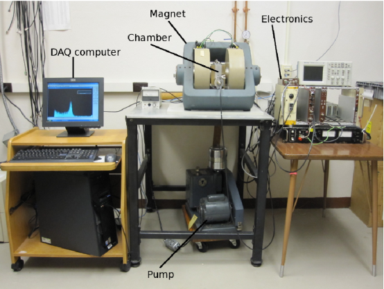
A photograph of the experimental setup is shown in Fig. 1. It consists of a vacuum chamber positioned between the poles of an electromagnet, a mechanical vacuum pump, electronics for the energy spectrometer and magnet, and a computer for data acquisition. We will describe the components and the experimental measurements below.
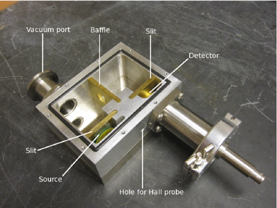
The inside of the vacuum chamber is shown in Fig. 2. It was designed using the SolidWorks 3D CAD programsolidworks and machined from a 12.0 8.9 3.7 cm block of 6061 aluminum. Grooves were cut on both faces for standard 1/8-inch O-rings. The vacuum port and detector feed-through are 2.3-cm inner diameter pipes with flanges for 1/8-inch O-rings on one end to connect to the chamber. The connections to the vacuum hose and the BNC feed-through for the detector are made with 1-inch Quick Flange connectors. Slits and baffles of various sizes were cut from 3/16-inch thick brass plates. The source is mounted behind one slit that is positioned 180∘ from an identical slit in front of the detector. The baffle is placed at the 90∘ position. The vacuum chamber face covers are stainless steel plates 12.0 8.9 1.9 cm with tapped holes for bolts that go through the poles of the magnet and hold the chamber in place. A 1/4-inch diameter hole is drilled into the outside body of the chamber so that a Hall probe can be inserted to measure the magnetic field between the poles of the magnet. A vacuum of around 50 mTorr is achieved using the mechanical vacuum pump.
The chamber is supported between the poles of an electromagnet with a variable pole gap, 4-inch diameter flat pole faces, and water-cooled coils.magnet A 40-V, 6-A, DC power supplymagnet_power_supply provides current for the magnet.
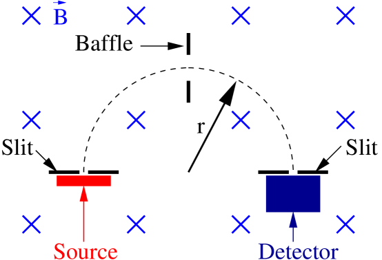
The vacuum chamber between the poles of the magnet serves as a semicircular -ray spectrometer. A diagram of the spectrometer is shown in Fig. 3. The slits and baffle define a semicircular path of radius . The momentum of electrons from the source that pass through the slit in front of the detector is calculated from measurements of the radius and the magnetic field . For the data presented here we used 2 12 mm slits and an 11 12 mm baffle, and the radius = 3.24 0.10 cm. This choice of slits and baffle provided a reasonable compromise between resolution and transmission of electrons. Based on the geometry,siegbahn we calculated the resolution of the spectrometer to be about 3.1 %.
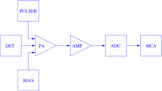
A silicon surface-barrier detectordetector with a thicknesses of 3 mm and an active area of 25 mm2 is used to measure the kinetic energy of the electrons. This detector is thick enough to stop the most energetic electrons from the source used in this experiment. A diagram of the electronics used to process the signals from the detector is shown in Fig. 4. The current signal from the detector (DET) is integrated with a preamplifierpreamp (PA) producing a voltage pulse that is amplified with a spectroscopy amplifieramp (AMP) and digitized with an analog-to-digital converteradc (ADC). Energy spectra are created and analyzed on the data acquisition computer using multi-channel analyzer emulator softwaremca (MCA). The bias for the detector is provided with a 3-kV, high-voltage, power supplybias (BIAS). We calibrate the energy spectrometer using the 624-keV electron conversion peak from a 137Cs source and a precision pulse generatorpulser (PULSER).
We use a sealed, 10-Ci, 204Tl -source to provide the relativistic electrons for this experiment. This source was chosen because it has a continuous spectrum with an end-point energy of 766 keV that is well into the relativistic regime, and it is inexpensive and readily available.source Other suitable sources include the continuous part of the 137Cs spectrum with an end-point energy of 514 keV and 210Bi with an end-point energy of 1.163 MeV.
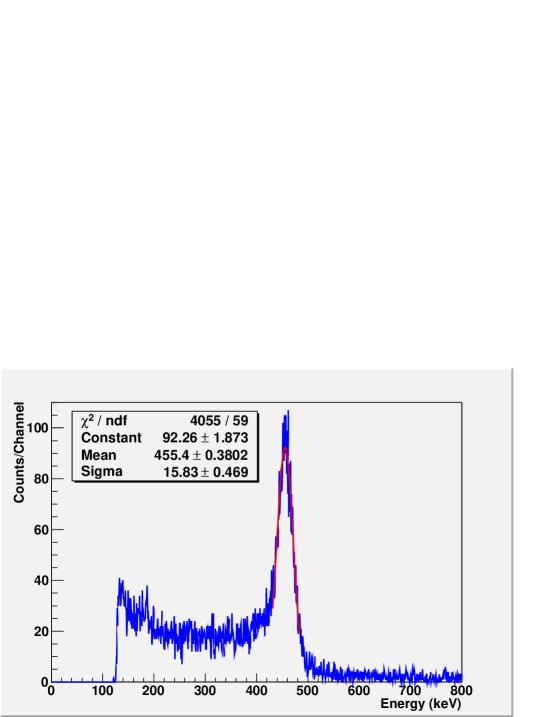
In performing the experiment, we collect electron energy spectra for different magnetic field settings between 500 and 1000 G (0.05 - 0.1 T). We measure the magnetic field at each setting by inserting a transverse Hall probe connected to a gaussmetergaussmeter into the small hole drilled into the side of the vacuum chamber. The momentum of electrons transmitted through the slit in front of the detector at each magnetic field setting is calculated using Eq. 5 and the measured values of the magnetic field and the radius . We fit the peak in the energy spectrum acquired at each magnetic field setting with a Gaussian to determine the kinetic energy associated with each momentum measurement. A typical energy spectrum for electrons with a momentum = 801 keV is shown in Fig. 5. The fit to the peak yields a mean value of = 455 keV with a standard deviation = 16 keV. Because the relative intensity of the spectrum decreases with increasing energy, the data acquisition time must be increased as the magnetic field is increased to get sufficient statistics in each peak. With a 10-Ci 204Tl source, 2-mm slits, and an 11-mm baffle, typical run times are 2 to 12 hours per point.
IV Results
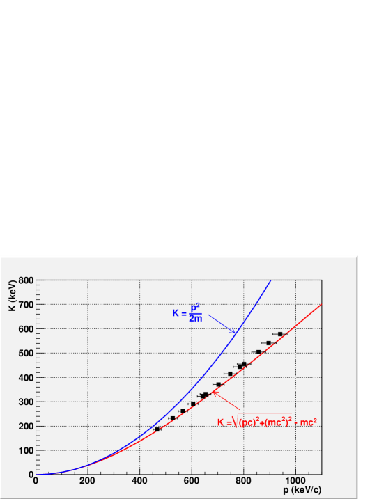
The results for thirteen magnetic field settings between 480 and 970 G are shown in Fig. 6 where the kinetic energy is plotted as a function of the momentum . We have assigned errors of 3.2% on the values of momentum based on the uncertainties in the measurements of (3.1%) and (1%). The uncertainties in the measurements of the kinetic energy were at most 0.5% resulting in error bars that are smaller than the squares representing the data points. The classical and relativistic relationships are shown as curves on the figure. There is good agreement between the data and the relativistic prediction, clearly illustrating the relativistic nature of the electrons.
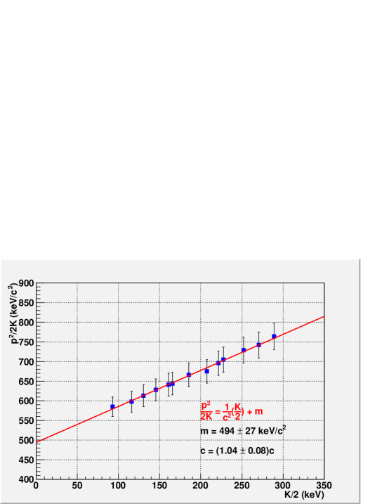
The data plotted as versus are shown in Fig. 7. The line is a fit to the data used to extract values for the rest mass of the electron and the speed of light in a vacuum of 494 27 keV/c2 and (1.04 0.08)c, respectively. These results agree with the accepted values within the experimental uncertainties.
V Summary
We have developed an experiment in which undergraduate students make independent measurements of the momentum and kinetic energy of electrons from a -source. The results clearly illustrate relativistic effects and values for the rest mass of the electron and the speed of light can be extracted from the data that agree with the accepted values within the experimental uncertainties.
The first version of this experiment was developed by one of us (Marvel) as an undergraduate senior thesis project in 2006-07 and it is now a regular part of the advanced laboratory course at Union College.
Acknowledgements.
We thank Christopher C. Jones, Emeritus Professor of Physics at Union College, for bringing the idea for this experiment to our attention, and John Sheehan, the technician/machinist for the Union College Department of Physics and Astronomy, for his assistance in the design and construction of the experimental apparatus. It is also a pleasure to thank Professor Chad Orzel at Union College for reading a draft of this paper and providing comments.References
- (1) A. A. Bartlett and Malcolm Correll, "An Undergraduate Laboratory Apparatus for Measuring e/m as a Function of Velocity," Am. J. Phys. 33, 327-339 (1965).
- (2) Sherwood Parker, "Relativity in an Undergraduate Laboratory–Measuring the Relativistic Mass Increase," Am. J. Phys. 40, 241-244 (1972).
- (3) Kenneth N. Geller and Richard Kollarits, "Experiment to Measure the Increase in Electron Mass with Velocity," Am. J. Phys. 40, 1125-1130 (1972).
- (4) Jack G. Couch and Terry K. Dorries, "Measuring relativistic electrons in the undergraduate laboratory," Am. J. Phys. 50 (10), 917-921 (1982).
- (5) John W. Luetzelschwab, "Apparatus to measure relativistic mass increase," Am. J. Phys. 71 (9), 878-884 (2003).
- (6) M. Lund and U. I. Uggerhoj, "Experimental special relativity with a meter stick and a clock," Am. J. Phys. 77 (8), 757-766 (2009).
- (7) J. Higbie, "Undergraduate Relativity Experiment," Am. J. Phys. 42, 642-644 (1974).
- (8) P. A. Egelstaff, J. A. Jackman, P. J. Schultz, B. G. Nickel, and I. K. MacKenzie, "Experiments in special relativity using Compton scattering of gamma rays," Am. J. Phys. 49 (1), 43-47 (1981).
- (9) Matthiam J. H. Hoffman, "The Compton effect as an experimental approach toward relativistic mass," Am. J. Phys. 57 (9), 822-825 (1989).
- (10) P. L. Jolivette and N. Rouze, "Compton scattering, the electron mass, and relativity: A laboratory experiment," Am. J. Phys. 62 (3), 266-271 (1994).
- (11) Jerzy Dryzek, Douglas Singleton, Takenori Suzuki, and Runsheng Yu, "An undergraduate experiment to test relativistic kinematics using in flight positron annihilation," Am. J. Phys. 74 (1), 49-53 (2006).
- (12) Jerzy Dryzek and Douglas Singleton, "Test of the second postulate of special relativity using positron annihilation," Am. J. Phys. 75 (8), 713-717 (2007).
- (13) SolidWorks 3D CAD software, http://www.solidworks.com/.
- (14) Cenco Model H Electromagnet, Cenco Physics by Sargent-Welch, http://www.cencophysics.com/magnets/c/5062/.
- (15) Sorensen Model SRL 40-6 Power Supply, AMETEK Programmable Power INc., San Diego, CA 92121, http://www.sorensen.com/.
- (16) Kai Siegbahn, Alpha-, Beta-, and Gamma-Ray Spectroscopy (North-Holland Publishing Company, Amsterdam, 1965) pp. 87-96.
- (17) Model CB-030-025-3000 detector from Ortec, Advanced Measurement Technology, Inc., Oak Ridge, Tennessee 37831-0895, http://www.ortec-online.com/.
- (18) Ortec 142 AH Preamplifier, Ortec, Advanced Measurement Technology, Inc., Oak Ridge, Tennessee 37831-0895, http://www.ortec-online.com/.
- (19) Ortec 570 Spectroscopy Amplifier, Ortec, Advanced Measurement Technology, Inc., Oak Ridge, Tennessee 37831-0895, http://www.ortec-online.com/.
- (20) Ortec 926 ADCAM MCB, Ortec, Advanced Measurement Technology, Inc., Oak Ridge, Tennessee 37831-0895, http://www.ortec-online.com/.
- (21) Ortec Maestro-32 MCA Emulator Software, Ortec, Advanced Measurement Technology, Inc., Oak Ridge, Tennessee 37831-0895, http://www.ortec-online.com/.
- (22) Bertan Model 303 HV Supply, Spellman High Voltage Electronics Corp., Valhalla, NY 10595, http://www.spellmanhv.com/.
- (23) Ortec 419 Precision Pulse Generator, Ortec, Advanced Measurement Technology, Inc., Oak Ridge, Tennessee 37831-0895, http://www.ortec-online.com/.
- (24) Spectrum Technologies, LLC, Oak Ridge, Tennessee 37830, http://www.spectrumtechniques.com/.
- (25) F. W. Bell Model 5180 Gauss/Tesla Meter, Pacific Scientific-OECO, Milwaukie, OR, http://fwbell.com/index2.html.