Metamaterial-based polarization control plate for producing incoherent laser irradiation
Abstract
We present a metamaterial-based random polarization control plate to produce incoherent laser irradiation by exploiting the ability of metamaterial in local polarization manipulation of beam upon transmission via tuning its local geometry. As a proof-of-principle, we exemplify this idea numerically in a simple optical system using a typical L-shaped plasmonic metamaterial with locally varying geometry, from which the desired polarization distribution can be obtained. The calculating results illustrate that this scheme can effectively suppress the speckle contrast and increase irradiation uniformity, which has potential to satisfy the increasing requirements for incoherent laser irradiation.
I Introduction
Coherence is a fundamental property of laser, which facilitate laser to be widely applied in those fields requiring high coherent light sources. However, just as a coin has two sides, coherence is harmful to some laser application fields. High coherence usually results in unwanted speckle noise in laser display (or laser projection imaging or laser TV), thereby decreasing the imaging resolution Mandel1995 . In laser fusion and laser heat processing, coherence makes the intensity distribution on the focal plane not uniform enough Deng1986 . In some spectroscopy experiments, high coherence laser is also undesirable. Thus, in these applications, it is urgently need to eliminating the laser coherence.
In essence, controlling the polarization or phase of laser beam could achieve incoherent laser irradiation. The key points of beam docoherence through polarization control can be summarized as follows. It first breaks a laser beam into two or many beamlets with orthogonal or random polarization distribution and then converge them; the irradiation on the focal plane is thereby incoherent. Some concrete schemes have been proposed, such as using a birefringent wedge to create two orthogonally polarized beams with a selected angular separation and employing an optic made by wave plates to scramble the polarization distribution in the near field LLE1990 ; Tsubakimoto1992 ; Rothenberg2000 ; Munro2004 . Generally, these polarization control devices are made of nematic liquid crystal, KDP crystals, and crystal half-wave plates, etc.
On the other hand, as artificial periodic subwavelength structures, metamaterial can exhibit strong anisotropy by suitably designing its microscopic structure unit Smith2004 ; Hao2007 . Generally, naturally existing anisotropic mediums exhibit very small birefringent index in optical domain, which need relatively thick slabs to achieve a polarization control device (e.g., hundreds or thousands of wavelengths for a half-wave plate). However, it is possible for metamaterial to achieve a polarizer with the same polarization conversion efficient as convention anisotropic mediums, with its thickness less than a wavelength and transverse dimension in the order of wavelength Rogacheva2006 ; Liu2007 ; Chin2008 ; Gansel2009 ; Wu2011 . So it holds great potential in the future nanophotonics applications, and is particularly amenable to miniaturization. From this point of view, it would be interesting to apply metamaterial in polarization control devices.
In this work, a metamaterial-based random polarization control plate (MRPCP) is proposed for eliminating the laser coherence and producing incoherent laser irradiation. Locally tailoring the geometric structure parameters of an anisotropic metamaterial, we could obtain a locally varying polarization response of laser beam passing through it, thereby scrambling the polarization state of beam in the near field and finally eliminating the laser coherence on the focal plane. Without loss of generality, we will exemplify our scheme numerically using a variation of the typical L-shaped metamaterial, although the approach can be applied to an arbitrary metamaterial geometry offering enough number of free design parameters. The calculating results show that the MRPCP can effectively suppress the speckle contrast and increase irradiation uniformity.
II Theory and scheme
The mechanism of MRPCP can be considered by employing the multi-beam interference formula
| (1) | |||||
where , , and represent the polarization direction vector, field amplitude, and phase of the ()th field, respectively. is the total intensity with location () and time () dependence. It is obvious that incoherent addition of the beamlets is achieved when their polarization vectors are random, since the vector summation of the interference term (the second term) in Eq. (1) is zero. This is the basis of the polarization docoherence.
The intensity distribution of MRPCP combined with a random phase plate (RPP) is referred to as laser speckle Kato1984 ; Dixit1993 . The statistical property of the speckle intensity can be considered as the addition of two orthogonally polarized speckle patterns (such as in - and -directions) Dainty1984 ; Goodman2006 . Due to the non-equivalence of the two speckle intensities (), the probability density of the intensity can be calculated by Dainty1984 ; Goodman2006
| (2) | |||||
with indicating the average intensities of the two speckle patterns. Because of the incoherency of the two orthogonal components, we have , and then Eq. (2) can be written as
| (3) | |||||
where and represent and , respectively. The speckle contrast is also reduced and determined by the ratio of and . The formula for calculating the contrast is Goodman2006
| (4) |
When , take the minimum value 0.707. It means that the speckle contrast can be reduced 29.3 at most by using MRPCP.
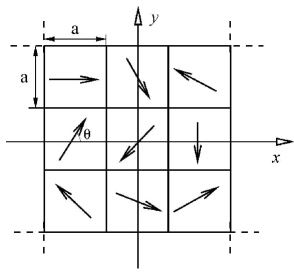
For the convenience of calculation, we now design a MRPCP using L-shaped plasmonic metamaterial, which requires it producing a random polarization distribution. A simple scheme is to make the optic-axis of the metamaterial taking random orientations for different local regions, namely, locally varying the structure geometry could create an MRPCP. The schematic picture of the MRPCP is shown in Fig. 1 where the arrows indicate the -rays of the anisotropic metamaterial elements. It is assumed that the number of the elements is ( and are both positive integers). An element is comprised of several L-shaped unit cells with the same orientation (-rays) and subwavelength dimension, and the number of the unit cell for each element is not restricted.
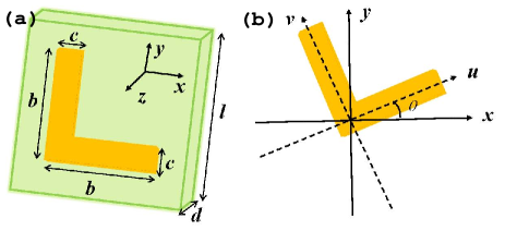
We first consider the polarization change of an element. The schematic picture of the metamaterial unit cell is shown in Fig. 2(a). The “L” is assumed to be made of gold with 20 nm thickness and built on a dielectric substrate (). They together form a unit cell of the metamaterial. Other structure parameters are labeled in the figure. We start by employing the complex Jones matrix of this metamaterial element Menzel2010 . It can be utilized to describe the transmission of coherent light through any dispersive optical system. The complex Jones matrix associating the complex amplitudes of the incident field () with the transmitted field () is given as
| (11) |
Here, it is assumed that and the incident plane wave propagates in positive -direction (normal incidence).
Both arms of the “L” are mutually perpendicular with identical structure dimensions. This indicates that and . The arms can be seen as oscillators with respective eigenfrequency, which are associated with the excitation of carriers representing the free-electron gas of the metal. The carrier dynamics of one arm is affected by the external electric field as well as the conductive coupling from another arm Raab2005 ; Petschulat2010 . Due to the identical structure dimensions, the eigen resonant responses of the two arms are identical as well as the conductive coupling responses. So we can safely obtain that and .
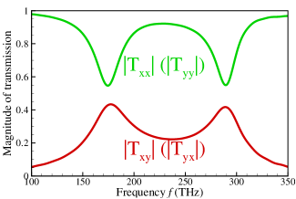
In order to solve and , we use the finite-difference time-domain method Tavlove1995 to simulate the metamaterial unit cell shown in Fig. 2(a). In the simulations, the metal permittivity is described by Drude model: , with the bulk plasma frequency and the relaxation rate . For gold, from literature Ordal1983 , THz and THz. The magnitudes of () and () are plotted in Fig. 3 when the incident electric field only polarized in - (-)direction. Each curve has two valleys (or peaks) which means that each oscillator has two distinct eigenmodes near the frequencies 173 THz and 290 THz, respectively Petschulat2010 . It also indicates that, if the incident electric field is polarized in either direction of the two arms, cross-polarized radiation will generate and of course result in polarization change in the transmitted field. In fact, the structure dimensions including the length and thickness of the arms can affect the resonant responses of the metamaterial, e.g., longer length or thinner thickness of the arms would decrease the resonant frequencies.
Now, the Jones vector of the transmitted field can be calculated according to Eq. (11). Without loss of generality, when takes an arbitrary value [see Fig. 2(b)], the Jones vector can be obtained by transformed the coordinate system to the coordinate system:
| (18) |
where
| (21) |
According to Eq. (18), at any frequency, we can obtain the dependence of the polarization states of the transmitted field. It’s worth noting that the matrix can be diagonalized by a rotation of or - since and , which indicates that the angle bisector direction of “L” and its orthogonal direction represent the - and -rays of the anisotropic metamaterial, respectively.
If both arms of the unit cell are non-identical, is not equal to , but can still be obtained. The matrix could no longer be diagonalized whatever value is. Therefore, actually, we have another degree of freedom to design the MRPCP, i.e., changing the geometric dimensions of the L’s arms. Arms with different length and thickness will induce different optical resonance responses (i.e., different matrix elements). The matrix can be simulated for a number of slightly varying dimensions of “L”, resulting in a look-up table linking geometric parameters with matrix elements. This table represents the set of possible building blocks of the MRPCP.
III Application of the MRPCP for suppressing the speckle contrast and increasing irradiation uniformity
As a proof-of-principle for the effectiveness of MRPCP in suppressing the speckle contrast and increasing irradiation uniformity, a simple optical system is considered here and schematically illustrated in Fig. 4. A plane wave polarized in the -direction () with unit amplitude is assumed for incident laser. It illuminates the MRPCP and is converged by a lens after passing through a RPP.

According to Eq. (18), we can obtain the transmitted field of and components from the ()th metamaterial element of the MRPCP:
| (26) |
From Eq. (26), it is easily to find that light arising from different metamaterial elements with random values will undergo different polarization change. When a laser beam passing through the random MRPCP, its transverse distribution of polarization state will be scrambled in the near field and thus make its spatial coherence become worse. Then, after passing through a RPP adjacent to the MRPCP, we converge the beamlets by a lens with focal length . As and have been calculated above by the finite-difference time-domain method, the field distribution on the focal plane can be derived from the Fresnel-diffraction integral formula: Goodman2005
| (27) | |||||
where and are axes parallel to the and axes, respectively, is the space range of the RPP illuminated by the th element of the MRPCP, is the random phase of the RPP element which is equal to either 0 or , and . The component of the total electric field is given by
| (28) |
and then the intensity of the total electric field can be written as
| (29) | |||||
Now, we calculate the intensity distribution on the focal plane. The parameters used for the calculations are mm, m. The operation wavelength is set as 1.5 m (i.e., THz). The total number of the metamaterial elements is whose values of are random numbers between 0 and produced by the computer. The number of the metamaterial elements should not be too few so as to fully randomize the polarization state. The RPP has 64 64 square phase elements (side length 0.5 mm), and is placed after the MRPCP. The size of the metamaterial elements are larger than the phase elements in order that one metamaterial element can illuminate at least one phase element. The shape and size of the speckle pattern are determined by those of the individual RPP elements.
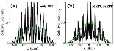
The normalized one-dimensional intensity distributions of the speckle patterns on the focal plane for only using RPP and MRPCP+RPP are shown in Fig. 5. The dense spikes come from the interference among the beamlets, and the intensity envelope (the so-called Airy spot indicating by green lines in Fig. 5) is determined by the diffraction of each element of RPP. One can notice that there is almost no zero-intensity in the central main region for MRPCP+RPP, while numerous zero-intensities for only using RPP. Also shown in Fig. 5, the introduction of MRPCP substantially reduces the contrast between the “spikes” and envelope. For further understanding these results, we will statistically analyze the intensity distributions obtained using them. The statistical results are calculated by considering thousands of points of the speckle pattern on the focal plane.
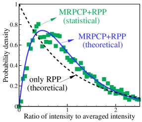
The probability density of intensity for one speckle pattern behaves as a negative exponential distribution (dashed line in Fig. 6), such as for the case of only using RPP Dixit1993 . For MRPCP+RPP, statistical results from the focal plane show that the average intensities of the two orthogonal directions are non-identical ( and ), because the number of the element of MRPCP in our real calculations is finite. Theoretically, the shape of the probability density distribution depends on the ratio of the two average intensities and . For comparison, we directly calculate the probability density of MRPCP+RPP from Eq. (3), and draw it in Fig. 6 (blue line). It indicates that the probability of zero-intensity is zero and the maximum probability moves toward the higher intensity. This theoretical results are well in accordance with the statistical ones (indicating by green squares in Fig. 6). The speckle contrast is also reduced and determined by Eq. (4), here, . The reduction of the speckle contrast is about 28.9 which is approaching to the ideal value 29.3.
Actually, incoherent laser irradiation are required by many applications fields, such as in laser display, laser fusion, laser heating processing, and some spectroscopy experiments. Our scheme holds great potential in these applications, especially enables to produce incoherent irradiation at very small dimensions (e.g., in the order of wavelength) due to the subwavelength structure features of metamaterial, which is not feasible for previous methods. An example is fabricating such structure directly at the tip of an optical fiber to form a compact device for beam decoherence Feng2011 .
IV Conclusions
We have proposed a metamaterial-based random polarization control plate for eliminating the coherence of laser and producing incoherent laser irradiation, since metamaterial can offer degrees of freedom to tailor their transmission and polarization properties by locally changing its structure geometry. A random polarization control plate based on L-shaped plasmonic metamaterial has been designed, which has locally varying structure parameters from which the desired far-field polarization distribution can be obtained. The calculating results show that it can effectively suppress the speckle contrast and increasing irradiation uniformity, which is potential to satisfy the increasing requirements for incoherent laser irradiation and especially enables beam decoherence at very small dimensions.
Acknowledgements.
The author X. Ling sincerely thanks the anonymous referees for their valuable suggestions. This research was partially supported by the National Natural Science Foundation of China (Grant Nos. 61025024 and 11074068).References
- (1) L. Mandel and E. Wolf, Optical coherence and quantum optics (Cambridge U. Press, 1995), Sec. 5.4.3.
- (2) X. Deng, X. Liang, Z. Chen, W. Yu, and R. Ma, “Uniform illumination of large targets using a lens array,” Appl. Opt. 25, 377 (1986).
- (3) Laboratory for Laser Energetics, “Phase conversion using distributed polarization rotation,” Laboratory for Laser Energetics Rev. 45, 1 NTIS Document No. DOE/DP40200-149 (1990).
- (4) K. Tsubakimoto, M. Nakatsuka, H. Nakano, T. Kanabe, T. Jitsuno, and S. Nakai, “Suppression of interference speckles produced by a random phase plate, using a polarization control plate,” Opt. Commun. 91, 9(1992).
- (5) J. E. Rothenberg, “Polarization beam smoothing for inertial confinement fusion,” J. Appl. Phys. 87, 3654 (2000).
- (6) D. H. Munro, S. N. Dixit, A. B. Langdon, and J. R. Murray, “Polarization smoothing in a convergent beam,” Appl. Opt. 43, 6639(2004).
- (7) D. R. Smith, J. B. Pendry, and M. C. K. Wiltshire, “Metamaterials and negative refractive index,” Science 305, 788 (2004).
- (8) J. Hao, Y. Yuan, L. Ran, T. Jiang, J. A. Kong, C. T. Chan, and L. Zhou, “Manipulating electromagnetic wave polarizations by anisotropic metamaterials,” Phys. Rev. Lett. 99, 063908 (2007).
- (9) A. V. Rogacheva, V. A. Fedotov, A. S. Schwanecke, and N. I. Zheludev, “Giant gyrotropy due to electromagnetic-field coupling in a bilayered chiral structure,” Phys. Rev. Lett. 97, 177401 (2006).
- (10) H. Liu, D. A. Genov, D. M. Wu, Y. M. Liu, Z. W. Liu, C. Sun, S. N. Zhu, and X. Zhang, “Magnetic plasmon hybridization and optical activity at optical frequencies in metallic nanostructures,” Phys. Rev. B 76, 073101 (2007).
- (11) J. Y. Chin, M. Lu, and T. J. Cui, “Metamaterial polarizers by electric-field-coupled resonators,” Appl. Phys. Lett. 93, 251903(2008).
- (12) J. K. Gansel, M. Thiel, M. S. Rill, M. Decker, K. Bade, V. Saile, G. von Freymann, S. Linden, and M. Wegener, “Gold Helix Photonic metamaterial as broadband circular polarizer,” Science 325, 151 (2009).
- (13) C. Wu, H. Li, X. Yu, F. Li, and H. Chen, “Metallic Helix array as a broadband wave plate,” Phys. Rev. Lett. 107, 177401 (2011).
- (14) Y. Kato, K. Mima, N. Miyanaga, S. Arinaga, Y. Kitagawa, M. Nakatsuka, and C. Yamanaka, “Random phasing of high-power lasers for uniform target acceleration and plasma-instability suppression,” Phys. Rev. Lett. 53, 1057 (1984).
- (15) S. N. Dixit, I. M. Thomas, B. W. Woods, A. J. Morgan, M. A. Henesian, P. J. Wegner, and H. T. Powell, “Random phase plates for beam smoothing on Nova laser,” Appl. Opt. 32, 2543 (1993).
- (16) J. C. Dainty, ed., Laser Speckle and Related Phenomena (2nd edition) (Springer, Berlin, 1984).
- (17) J. W. Goodman, Speckle Phenomena in Optics (Ben Roberts and Co., Greenwood Village, CO, 2006).
- (18) C. Menzel, C. Rockstuhl, and F. Lederer, “Advanced Jones calculus for the classification of periodic metamaterials” Phys. Rev A 82, 053811 (2010).
- (19) R. E. Raab and O. L. D. Lange, Multipole Theory in Electromagnetism (Clarendon, Oxford, 2005).
- (20) J. Petschulat, A. Chipouline, A. Tünnermann, T. Pertsch, C. Menzel, C. Rockstuhl, T. Paul, and F. Lederer, “Simple and versatile analytical approach for planar metamaterials,” Phys. Rev. B 82, 075102 (2010).
- (21) A. Tavlove, Computational Electrodynamics: The Finite-Difference Time-Domain Method (Artech House, Norwood, Mass., 1995).
- (22) M. A. Ordal, L. L. Long, R. J. Bell, S. E. Bell, R. R. Bell, R. W. Alexander, and C. A. Ward, “Optical properties of the metals Al, Co, Cu, Au, Fe, Pb, Ni, Pd, Pt, Ag, Ti, and W in the infrared and far infrared,” Appl. Opt. 22, 1099 (1983).
- (23) J. W. Goodman, Introduction to Fourier Optics (3rd Edition) (Roberts & Company, 2005).
- (24) J. Feng, Y. Zhao, X.-W. Lin, W. Hu, F. Xu, and Y.-Q. Lu, “A transflective nano-wire grid polarizer based fiber-optic sensor,” Sensors, 11, 2488 (2011).