Enhanced and switchable spin Hall effect of light near the Brewster angle on reflection
Abstract
We reveal an enhanced and switchable spin Hall effect (SHE) of light near Brewster angle on reflection both theoretically and experimentally. The obtained spin-dependent splitting reaches 3200nm near Brewster angle, 50 times larger than the previous reported values in refraction. We find that the amplifying factor in week measurement is not a constant which is significantly different from that in refraction. As an analogy of SHE in electronic system, a switchable spin accumulation in SHE of light is detected. We were able to switch the direction of the spin accumulations by slightly adjusting the incident angle.
pacs:
42.25.-p, 42.79.-e, 41.20.JbI Introduction
The spin Hall effect (SHE) of light can be regarded as a direct optical analogy of SHE in electronic system where the spin electrons and electric potential are replaced by spin photons and refractive index gradient, respectively Onoda2004 ; Bliokh2006 ; Hosten2008 . Recently, the SHE of light has been intensively investigated in different physical systems, such as high-energy physics Gosselin2007 , plasmonics Gorodetski2008 , optical physics Bliokh2008 ; Haefner2009 ; Aiello2009 ; Herrera2010 , and semiconductor physics Menard2010 . The SHE of light is generally believed as a result of an effective spin-orbital interaction, which describes the mutual influence of the spin (polarization) and trajectory of the light beam. In general, the spin-dependent splitting in these physics systems is limited by a fraction of the wavelength, and therefore it is disadvantage for potential application to nano-photonic devices.
The SHE in electronic system offer an effective way to manipulate the spin particles, and open a promising way to potential applications in semiconductor spintronic devices Murakami2003 ; Sinova2004 ; Wunderlich2005 . The generation and manipulation of spin-polarized electrons in semiconductors define the main challenges of spin-based electronics Wolf2001 . In semiconductor systems, the spin accumulation can be switched by altering the directions of external magnetic field Kimura2007 ; Mihaly2008 . By rotating the polarization plane of the exciting light, the directions of spin current can be switched in a semiconductor micro-cavity Kavokin2005 ; Leyder2007 . Now a question arises: Whether there exists a similar phenomenon in SHE of light? In this paper, we want to reveal an enhanced and switchable SHE of light near Brewster angle on reflection. The SHE of light has been studied in reflection both in theory Bliokh2007 ; Aiello2008 ; Luo2009 and in experiment Qin2009 . However, the developed paraxial propagation model cannot be applied and the experimental evidence is still absent for describing the SHE of light near Brewster angle.
The paper is organized as follows. First, we develop a general propagation model to describe the SHE of light near Brewster angle on reflection. Next, we attempt to reveal the enhanced SHE of light in theory and detect the large spin-dependent splitting in experiment via week measurements. The large spin-dependent splitting is found to be attributed to the large ratio between the Fresnel reflection coefficients near Brewster angle. Finally, we want to explore the switchable SHE of light. We demonstrate that the transverse displacements can be tuned to either a negative, or a positive value, or even zero, by slightly adjusting the incident angle. The underlying secret can be interpreted from that the horizontal field component changes its phase across the Brewster angle. As an analogy of SHE in electronic system, the spin accumulations can be switched in the SHE of light.
II General propagation model
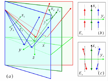
We first develop a general propagation model to describe the SHE of light near the Brewster angle on reflection. The axis of the laboratory Cartesian frame () is normal to the air-prism interface. We use the coordinate frames () and () to denote incident and reflection, respectively [Fig. 1(a)]. In the spin basis set, the incident angular spectrum can be written as:
| (1) |
| (2) |
Here, and represent horizontal and vertical polarizations, respectively. and denote the left and right circularly polarized (spin) components, respectively. We consider the incident beam whose angular spectrum with a Gaussian distribution:
| (3) |
where is the beam waist. The complex amplitude for the reflected beam can be conveniently expressed as
| (4) | |||||
where and is the reflected angular spectrum.
The reflected angular spectrum is related to the boundary distribution of the electric field by means of the relation Bliokh2006
| (11) |
where and denote the Fresnel reflection coefficients for parallel and perpendicular polarizations, respectively. By making use of Taylor series expansion based on the arbitrary angular spectrum component, and can be expanded as a polynomial of :
| (12) | |||||
The reflection coefficient changes its sign across the Brewster angle, which means the electric field reverses its directions [Fig. 1(b) and 1(c)]. The polarizations associated with the angular spectrum components experience different rotations in order to satisfy the boundary condition after reflection.
In the spin basis set, the reflected angular spectrum can be written as:
| (13) |
| (14) |
We consider the incident Gaussian beam with polarization. From the boundary condition, we obtain and . In fact, after the incident angular spectrum is known, Eq. (4) together with Eqs. (3)-(14) provides the general expression of the reflected field:
| (15) | |||||
where is the Rayleigh lengths. Our analysis is confined to the first order in Taylor series expansion of Fresnel reflection coefficients.
III Spin Hall effect of Light
We now determine the sin-dependent splitting of field centroid. At any given plane , the transverse displacement of field centroid compared to the geometrical-optics prediction is given by
| (16) |
The intensity distribution of beam is closely linked to the longitudinal momentum currents . The time-averaged linear momentum density associated with the electromagnetic field can be shown to be , where the magnetic field can be obtained by .
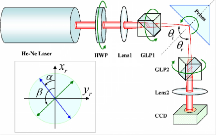
To detect the displacements, we use the signal enhancement technique Hosten2008 known from weak measurements Aharonov1988 ; Ritchie1991 . In principle, this enhancement mechanism of this setup can be perfectly presented in a classical description Aiello2008 . Figure 2 illustrates the experimental setup. A Gaussian beam generated by a He-Ne laser passes through a short focal length lens (Lens1) and a polarizer (GLP1) to produce an initially polarized focused beam. When the beam impinges onto the prism interface, the SHE of light generates. The prism was mounted to a rotation stage which allows for precise control of the incident angle . The incident beam is preselected in the polarization state () by GLP1, and then postselected () by GLP2 in the polarization state with
| (17) |
In our measurement, we chose . Note that the interesting cross polarization effect can be observed as Aiello2009b . As the reflected beam of light splits by several wavelengths, the intensity distribution on the prism interface is nearly unchanged. After the second polarizer GLP2, the two splitting components interfere, and produce a field redistribution whose centroid is significantly amplified. We use a CCD to measure the amplified displacement after a long focal length lens (Lens2).
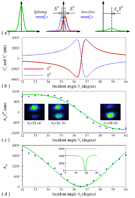
The week measurement of SHE of light is schematically shown in Fig. 3(a). The theoretical transverse displacements given in Eq. (16) show that the two opposite spin components would have opposite tendency versus [Fig. 3(b)]. It indicates that the SHE of light can be greatly enhanced near the Brewster angle. We obtain the value of spin-dependent splitting nm at and 50 times larger than the previous reported values of refraction Hosten2008 . The relevant amplitude of the reflected field at the plane of can be obtained as . The amplified displacement of field centroid at the CCD is much larger than the original displacement . Calculation of the centroid of the distribution of yields the amplifying factor . Our experimental results for the amplified displacement versus the incident angle are reported in Fig. 3(c). We measure the displacements every from to . The measure values allow for calculating the original displacement caused by SHE of light. The solid lines represent the theoretical predictions. It should be noted that the amplifying factor in week measurements is always the same in refraction Hosten2008 . However, it presents a valley near Brewster angle on reflection [Fig. 3(d)]. The experimental results are in good agreement with the theory without using parameter fit.
From Eq. (15), we know that the transverse displacements are related to the ratio between the Fresnel transmission coefficients and . The reflection coefficient of horizontal polarization vanishes at exactly the Brewster angle, and changes its sign across the angle. Hence, the large spin-dependent splitting in SHE of light is attributed to the large ratio of near the Brewster angle. On the contrary, a small ratio of would greatly suppress the SHE of light. It should be mentioned that a large value of near Brewster angle will lead to large Goos-Hanchen shifts Lai2002 and angular shifts Merano2009 . It should be noted that the horizontal component of electric field alters its phase, however the vertical component does not. As a result, the phase difference experiences a variation , and the spin accumulation would reverse its directions accordingly. Due to the reversed spin-dependent splitting, the spin accumulation can be switched by slightly adjusting the incident angle.
The SHE of light may open new opportunities for manipulating photon spin and developing new generation of all-optical devices as counterpart of recently presented spintronics devices Hosten2008 ; Wolf2001 . It should be mentioned that the spatial separation of the spin components is very small in the refraction. Hence, it is disadvantage for potential application to nano-photonic devices. In refraction Hosten2008 and photon tunneling Luo2010 the reversed spin accumulation requires the reversed refractive index gradient. As shown in above, the transverse displacements can be tuned to either a negative, or a positive value, or even zero, by just adjusting the incident angle. Hence, our scheme provide more flexibility for switching the direction of the spin accumulations. These interesting phenomena open a promising way to some potential applications in spin-based nano-photonic devices. Because of the close similarity of Brewster angle in optical physics, condensed matter Khodas2004 , and plasmonics Gordon2006 , by properly facilitating the reflection near Brewster angle, the SHE may be effectively modulated in these physical systems.
IV Conclusions
In conclusion, we have revealed an enhanced and switchable spin-dependent splitting near Brewster angle on reflection. The detected spin-dependent splitting reaches 3200nm near Brewster angle, and 50 times larger than the previous reported values in refraction. We have found that the amplifying factor is not a constant which is significantly different from that in the refraction case. The enhanced spin-dependent splitting is found to be attributed to the large ratio between the Fresnel reflection coefficients near Brewster angle. As an analogy of SHE in electronic system, the switchable SHE of light has been detected, which can be interpreted from the inversion of horizontal electric field vector across the Brewster angle. We were able to switch the directions of the spin accumulation, by slightly adjusting the incident angle near Brewster angle. These findings provide a novel pathway for modulating the SHE of light, and thereby open the possibility for developing new nano-photonic devices.
Acknowledgements.
This research was partially supported by the National Natural Science Foundation of China (Grants Nos. 61025024, 11074068, and 10904036).References
- (1) M. Onoda, S. Murakami, and N. Nagaosa, Phys. Rev. Lett. 93, 083901 (2004).
- (2) K. Y. Bliokh and Y. P. Bliokh, Phys. Rev. Lett. 96, 073903 (2006).
- (3) O. Hosten and P. Kwiat, Science 319, 787 (2008).
- (4) P. Gosselin, A. Bérard, and H. Mohrbach, Phys. Rev. D 75, 084035 (2007).
- (5) Y. Gorodetski, A. Niv, V. Kleiner, and E. Hasman, Phys. Rev. Lett. 101, 043903 (2008).
- (6) K. Y. Bliokh, A. Niv, V. Kleiner, and E. Hasman, Nature Photon. 2, 748 (2008).
- (7) D. Haefner, S. Sukhov, and A. Dogariu, Phys. Rev. Lett. 102, 123903 (2009).
- (8) A. Aiello, N. Lindlein, C. Marquardt, and G. Leuchs, Phys. Rev. Lett. 103, 100401 (2009).
- (9) O. G. Rodríguez-Herrera, D. Lara, K. Y. Bliokh, E. A. Ostrovskaya, and C. Dainty, Phys. Rev. Lett. 104, 253601 (2010).
- (10) J.-M. Ménard, A. E. Mattacchione, H. M. van Driel, C. Hautmann, and M. Betz, Phys. Rev. B 82, 045303 (2010).
- (11) S. Murakami, N. Nagaosa, and S. C. Zhang, Science 301, 1348 (2003).
- (12) J. Sinova, D. Culcer, Q. Niu, N. A. Sinitsyn, T. Jungwirth, and A. H. MacDonald, Phys. Rev. Lett. 92, 126603 (2004).
- (13) J. Wunderlich, B. Kaestner, J. Sinova, and T. Jungwirth, Phys. Rev. Lett. 94, 047204 (2005).
- (14) S. A. Wolf, D. D. Awschalom, R. A. Buhrman, J. M. Daughton, S. von Molnár, M. L. Roukes, A. Y. Chtchelkanova, and D. M. Treger, Science 294, 1488 (2001).
- (15) T. Kimura, Y. Otani, T. Sato, S. Takahashi, and S. Maekawa, Phys. Rev. Lett. 98, 156601 (2007).
- (16) G. Mihály, M. Csontos, S. Bordács, I. Kézsmarki, T. Wojtowicz, X. Liu, B. Jankó, and J. K. Furdyna, Phys. Rev. Lett. 100, 107201 (2008).
- (17) A. Kavokin, G. Malpuech, and M. Glazov, Phys. Rev. Lett. 95, 136601 (2005).
- (18) C. Leyder, M. Romanelli, J. Ph. Karr, E. Giacobino, T. C. H. Liew, M. M. Glazov, A. V. Kavokin, G. Malpuech, and A. Bramati, Nature Phys. 3, 628 (2007).
- (19) K. Y. Bliokh and Y. P. Bliokh, Phys. Rev. E 75, 066609 (2007).
- (20) A. Aiello and J. P. Woerdman, Opt. Lett. 33, 1437 (2008).
- (21) H. Luo, S. Wen, W. Shu, Z. Tang, Y. Zou, and D. Fan, Phys. Rev. A 80, 043810 (2009).
- (22) Y. Qin, Y. Li, H. Y. He, and Q. H. Gong, Opt. Lett. 34, 2551 (2009).
- (23) Y. Aharonov, D. Z. Albert, and L. Vaidman, Phys. Rev. Lett. 60, 1351 (1988).
- (24) N. W. M. Ritchie, J. G. Story, and R. G. Hulet, Phys. Rev. Lett. 66, 1107 (1991).
- (25) A. Aiello, M. Merano, and J. P. Woerdman, Opt. Lett. 34, 1207 (2009).
- (26) H. M. Lai and S. W. Chan, Opt. Lett. 27, 680 (2002).
- (27) M. Merano, A. Aiello, M. P. van Exter, and J. P. Woerdman, Nature Photon. 3, 337 (2009).
- (28) H. Luo, S. Wen, W. Shu, and D. Fan, Phys. Rev. A 82, 043825 (2010).
- (29) M. Khodas, A Shekhter, and A. M. Finkel’stein, Phys. Rev. Lett. 92, 086602 (2004).
- (30) R. Gordon, Phys. Rev. B 74, 153417 (2006).