Effects of MAC Approaches on Non-Monotonic Saturation with COPE - A Simple Case Study††thanks: This work is sponsored by the Department of Defense under Air Force Contract FA8721-05-C-0002. Opinions, interpretations, recommendations, and conclusions are those of the authors and are not necessarily endorsed by the United States Government. Specifically, this work was supported by Information Systems of ASD(R&E). Contributions of the Irwin Mark Jacobs and Joan Klein Jacobs Presidential Fellowship have also been critical to the success of this project.
Abstract
We construct a simple network model to provide insight into network design strategies. We show that the model can be used to address various approaches to network coding, MAC, and multi-packet reception so that their effects on network throughput can be evaluated. We consider several topology components which exhibit the same non-monotonic saturation behavior found within the Katti et. al. COPE experiments. We further show that fairness allocation by the MAC can seriously impact performance and cause this non-monotonic saturation. Using our model, we develop a MAC that provides monotonic saturation, higher saturation throughput gains and fairness among flows rather than nodes. The proposed model provides an estimate of the achievable gains for the cross-layer design of network coding, multi-packet reception, and MAC showing that super-additive throughput gains on the order of six times that of routing are possible.
I Introduction
With the multitude of network technologies available that increase performance, it is difficult to efficiently integrate them into a coherent network. We develop a simple model that provides insight into cross-layer network design, and illustrate its use through examples involving the combination of the 802.11 medium access control (MAC), network coding (NC), and multi-packet reception (MPR). Our model not only provides strategies to integrate various technologies, but also predicts the achievable gains possible.
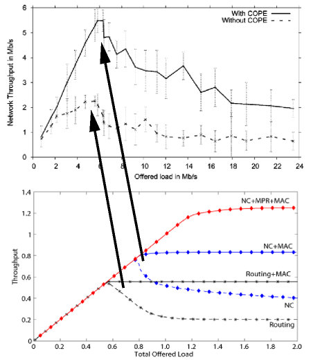
The development of the opportunistic inter-session NC scheme, COPE, by Katti et. al. [1] led to various models and analyses that attempted to explain COPE’s experimental results. Le et. al. [3] and Sengupta et. al. [4] developed models to describe these results, but only considered coding a maximum of two packets together at a time or did not address the interaction between NC and MAC fairness. As a result, their models provide throughput gains that are considerably smaller than the experimental results and do not explain the non-monotonic behavior shown in the upper half of Fig. 1. Zhao and Médard [2] showed that the fairness imposed by the 802.11 MAC helps to explain this non-monotonic behavior. In addition, they demonstrated that the majority of the throughput gain achieved from COPE is a result of coding three or more unencoded, or native, packets together at time. Their analysis showed that these gains are not reflected in three node network models and that at least five nodes are required to accurately capture the effects of COPE. Fig. 1 shows that the 802.11 model and 5-node cross topology component from [2] is consistent with the results from [1]. Furthermore, Seferoglu et. al. [5] has used similar 5-node topology components, and variants of them, to analyze TCP performance over coded wireless networks. With this in mind, we develop our model using the basic 5-node cross components from [2] and [5] and other possible combinations of these 5-node topology components in order to help in our understanding of the effects of combining NC and various MAC implementations in larger networks.
Finally, we demonstrate the capability of the model to predict the gains and highlight design challenges from incorporating additional technologies, such as MPR, into the network. MPR is known to enhance wireless network performance and has been extensively researched with unencoded traffic [6, 7, 8, 9]; but little on the joint use of MPR, NC, and MAC design exists. Garcia-Luna-Aceves et. al. [10] compared the use of NC to MPR, but did not consider their combined use; and Rezaee et. al. [11] provided an analysis of the combined use of NC and MPR in a fully connected network, but did not consider the effects of bottlenecks or multi-hop traffic. We show that our model provides an intuitive method for determining an estimate of the achievable gains from the combined use of MPR and NC in a congested, multi-hop network.
The remainder of the paper is organized as follows: Section II provides a detailed description of the network model; Section III provides an example of NC and MPR for 5-node network topology components using the existing 802.11 MAC; Section IV demonstrates the flexibility of using the model when considering the design of various network elements; and we conclude in Section V.
II Network models and parameters
Our main goal is to develop a simple model that gives insight into cross-layer design of wireless networks by using NC, various MAC approaches, and MPR as examples. To this end, we identify the fundamental behavior of each aspect of the network and model each element using simple, intuitive methods so that we can evaluate the potential throughput gains.
The performance of NC is modeled by considering the ability of a given node to combine multiple packets together as well as the primary implementation details of the particular NC scheme. We use COPE [1] as a case study. COPE uses the broadcast nature of the wireless channel to opportunistically code packets from different nodes together using a simple XOR operation. Any node that receives an encoded message is able to decode it using the unencoded, or native, packets captured from the wireless channel. We model COPE such that packet transmissions are never delayed. If a node does not have more than one packet to encode, it does not wait for another packet to arrive. Rather, it sends the packet unencoded at the first opportunity. In addition, all packets headed towards the same next-hop will not be encoded together because the next-hop would not be able to decode these coded packets due to the lack of enough degrees of freedom. We do not consider the complexity of the coding or decoding operations nor any other aspects of the NC implementation since their contributions to the overall network performance is small in relation to the specific implementation aspects mentioned above.
The MAC is modeled by identifying its primary behavior in the network and simplifications are made by assuming optimal performance from its secondary and tertiary behaviors. This gives us an intuitive approach in determining the potential throughput while ensuring that we understand the fundamental characteristics of the network. For instance, the 802.11 MAC employs a fairness mechanism that distributes channel resources equally among all competing nodes within a network. As we show in the following sections, this is the primary cause of the non-monotonic saturation behavior in the experimental throughput shown in the upper half of Fig. 1. Since the fairness mechanism is the major contributor to overall network performance, we assume optimal performance from all other aspects of the MAC. For example, the non-monotonic behavior is a result of both collisions and fairness; but the total effects of collisions from either hidden nodes or identical back-off times on throughput are small in relation to the effects of the 802.11 MAC fairness mechanisms. Furthermore, we do not consider the additional effects on overall throughput associated with the virtual 802.11 CS mechanisms (RTS/CTS) or other aspects of the MAC such as the potential of lost channel resources due to the MAC’s random back-off. Instead, we assume optimal performance from each of these secondary and tertiary behaviors. These assumptions, as a result, provide upper bounds to the achievable throughput in the various networks that employ the MAC.
We also show how additional techniques to increase network performance, such as MPR, can be similarly modeled. MPR can be implemented in a variety of methods from Code Division Multiple Access (CDMA) or multiple-input-multiple-output (MIMO) to orthogonal frequency division multiple access (OFDMA). In subsequent sections, we model MPR by allowing each node to successfully receive multiple packets at the same time.
Finally, our model uses several basic canonical topology components that contain only five nodes where each node is both a source and a sink. Two of the possible components are shown in Fig. 2. These components are of interest because they form the primary structures in larger networks that create bottlenecks and congestion. By looking at the traffic that travels through the center node, these components help us model the performance gains of multi-hop traffic under both low and high loads. While all possible combinations of these basic canonical topology components should be evaluated, we only focus on two of the components, shown in Fig. 2, since the analysis of the others are redundant and provide little to the clarification of our approach.
Each component has specific constraints due to their structure and will effect the performance of the MAC, NC, and MPR in different ways. The center node in each component is fully connected regardless of the topology, and traffic flows originating from the center require only a single hop to reach their destination. Within the cross topology component, each traffic flow originating from a given node is terminated at the node directly opposite the center; and in the “X” topology component, all flows originating from a node in a given set terminates at a node in the opposite set. Therefore, each flow must pass through the center regardless of topology. For example, nodes , , and in the “X” topology component are fully connected and nodes , , and are also fully connected; but and are not connected to and . All traffic between any node and any node must travel through the center.

In an effort to simplify the following explanation, we make several additional simplifications which can be easily incorporated into the model. We assume feedback is perfect, the load required for acknowledgments are contained as part of the initial transmission’s load, and the wireless channel is loss-less. We also consider the additional constraint that each node is half-duplex, i.e. a node will overhear any transmission from its neighbors only if it is not transmitting. When considering the model for MPR, we allow packets to be sent from different sources in a single time slot with the constraint that we try to maximize the number of neighbors a node can overhear within any given time slot. In essence, we duplicate CSMA/CA for each case in the sense that a node will transmit only if none of its neighbors are transmitting. For cases where , we pick the combination of transmitting nodes such that the average number of transmissions received by any given node within the network is maximized.
Sections III and IV provide both an analysis of the maximum achievable throughput and simulations over various values of the total offered load to the network. The load to the network from the set of source nodes , is defined as , where is the set of nodes in the topology component and is node ’s individual load contribution, or the fraction of time required to send all of its packets to the next-hop. We stochastically determine using a binomial distribution given with parameters and , , in each iteration of our simulation and average these results for each total offered load evaluated. We then use the model described in this section to determine the total network throughput which is equivalent to the total number of packets divided by number of time slots needed to send every packet to its intended destination.
III Multi-Packet Reception and Network Coding Performance Analysis
With each of the network topology components shown in Fig. 2, we provide an example of the performance analysis with and without the use of NC and MPR when the 802.11 MAC is used. We also consider both unicast and broadcast traffic where a unicast transmission is complete when all packets from each source successfully reaches their destination and a broadcast transmission is complete when all nodes have received every packet from all sources.
III-A Cross Topology Component Analysis
Each node , requires of the time to send all of its packets one hop. The resulting total offered load to the network is then . We define the total network component load as the time required to send all packets through the topology component where is the required load to relay packets and is the required load to send each native packet one hop. The load required to relay packets through the center is where is the number of packets that can be encoded together which is dependent on the number of neighbors a given node can overhear. In the case of the cross topology component and enough packets to code together, for and for all . The load needed to send each node’s unencoded packets one hop is defined as . Because we setup the model so that we maximize the number of neighbors any given node can overhear when using MPR, this expression is met with equality if each , , is equal. Otherwise, the load is lower bounded by this equation and is a function that is dependent on both the topology component’s configuration and each node’s load imbalance. Finally, let the fraction of allocated time slots a node receives as a result of the MAC be .
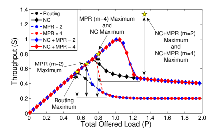
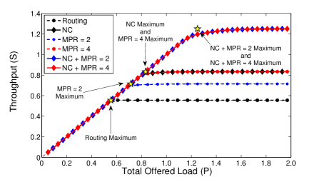
The throughput with unicast and broadcast traffic is shown as a function of in Fig. 3. Each curve is obtained through simulation and is an average over the load distribution discussed in Section II. Each star is obtained by analysis and depicts the maximum achievable throughput when the MPR and/or NC gain is maximized. When , each node is allocated enough time slots to send all of its packets, and the allocated load is for and . The throughput increases linearly as the network load increases, regardless of the use of MPR or NC, and reaches a maximum for each case when . The throughput then transitions into a saturated region for , where the allocated load for each node is and . When NC is not used, the throughput is ; and when NC is used, the throughput will be a function of the number of packets that can be encoded together.
III-A1 Routing (No Network Coding, )
We use routing as the performance baseline. Consistent with the results found in [1] and the analysis performed in [2], the throughput increases linearly within the non-saturated region, . At , the throughput reaches a maximum of (depicted by a star in Fig. 3). This occurs when each sources’ load reaches for . The total load of the center node, as a consequence, is where . Since , and .
The throughput saturates for . Initially, the 802.11 MAC allocates time slots to nodes requiring more resources. The throughput is therefore the amount of time is able to transmit, , which decreases as increases. The network component completely saturates when each node requires a large fraction of the available time slots but the MAC restricts each node’s access to the channel by ensuring fairness among each competing node, i.e. for . For large enough , the throughput saturates to the total amount of information that can transmit, i.e., .
III-A2 Network Coding Only ()
We now allow NC to be used by the center node. Each node transmits one at a time, allowing each node to receive four native packets or four degrees of freedom (three degrees of freedom through the use of opportunistic listening plus one degree of freedom from the packet originating at the node). After each edge node has completed transmission, node transmits a single encoded packet, which is sufficient for each edge node to obtain the single degree of freedom it still requires to complete both the unicast and broadcast sessions.
From Fig. 3, when , NC is seen to provide no additional gains over the use of routing alone since can forward each packet received without the MAC limiting its channel use. For NC is instrumental in achieving the throughput shown. The MAC does not limit channel resources until the maximum throughput of is reached when where for . At this maximum, the MAC ensures fairness among all competing nodes and the throughput saturates. As increases, the gain provided by NC diminishes. The number of packets reaching from each edge node is limited by the MAC while packets introduced into the network component by are not. The coding gain, therefore, approaches zero as .
III-A3 Multi-Packet Reception of Order 2 and 4 (No Network Coding and )
MPR is similar to the routing case described earlier except we now allow a maximum of edge nodes to transmit within a given time slot. For , the total time used by all of the edge nodes to transmit their packets to is that needed by routing while the center node cannot transmit multiple packets simultaneously and must transmit each received packet individually. Using CSMA, which restricts nodes opposite each other to transmit at the same time, the point at which the protocol saturates for symmetric source loads occurs when where for . This yields the maximum throughput of . The throughput saturates to the same throughput as routing for values of and the gain for in the saturated regime is 1 due to the suboptimal saturation behavior of the protocol.
The behavior for is the same as that for except the maximum of occurs when where . We allow all edge nodes to transmit their packets to simultaneously, requiring a total of of the time-slots. Node then sends each node’s packet individually, including its own, to the intended recipient requiring the remainder of the time slots to finish each unicast/broadcast transmission. As increases, the MAC limits each node’s number of available time slots and saturates to . Again, the gain in the saturated region for is equal to the cases of and routing.
III-A4 Network Coding with Multi-Packet Reception of Order 2 and 4 ()
For , the maximum throughput of occurs when where for . Each set of nodes, and , uses of the total number of time slots to transmit to which then transmits a single encoded packet derived from all four node’s native packets in addition to its own native packet. For , the throughput saturates to the saturated NC throughput due to the 802.11 MAC. While the maximum achievable throughput is times the NC without MPR throughput, the saturated gain for is equal to the gain found when NC was used alone in this region.
The throughput using NC and for unicast traffic is equivalent to NC and . All four edge nodes transmit to which then transmits two encoded packets in addition to its own; or we limit the number of simultaneous transmissions to two thus allowing to code everything together and send a single encoded packet to all of the edge nodes. Either strategy will achieve the same gain although the difference occurs when considering either unicast (former option) or broadcast (later option). The maximum throughput for broadcast traffic using the first method is , and for the second which is consistent with the maximum unicast throughput. This difference indicates that increasing when using NC may not be the optimal strategy. Although we do not show it here, the canonical topology components can be easily modified to include any number of nodes which would allow us to further look into the optimal strategy for broadcast traffic.
III-B “X” Topology Component
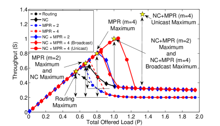
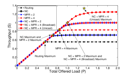
The cross topology component gives insight into the performance of COPE and MPR in a dense network, and it represents the best case scenario when COPE is used since it maximizes the number of transmissions any given node receives. In order to understand the behavior of COPE and MPR in sparser networks, we limit the number of each node’s neighbors by analyzing the behavior of COPE and MPR in the “X” topology component shown Fig. 2(b). Fig. 4 shows both the maximum and average throughput resulting from the use of the “X” topology component. Within this section, we focus only on the cases involving NC since it can be easily verified that the routing and analysis for this topology component are the same as the cross topology component analysis.
III-B1 Network Coding Only ()
Limiting the ability to overhear other edge nodes in the component results in the reduction in the number of possible packets that can be encoded together. Packets from different nodes within the same set, i.e. and , cannot be encoded together because all flows transitioning between and are effectively headed towards the same next-hop. This forces to code only a subset of packets together which increases the number of transmissions the center node must make. For example, the center node must make a minimum of two transmissions for every four packets it receives from different edge nodes in order to ensure that each node has the necessary degrees of freedom to decode all of the packets.
Like the cross component’s throughput, the throughput of the “X” topology component increases linearly until it reaches its maximum at . Assuming symmetric source loads, this maximum occurs when where for . The throughput saturates for and the non-monotonic behavior in the saturated throughput regime is again due to the fairness aspect of the 802.11 MAC. By comparing the results obtained from both the cross and “X” topology components, it is evident that the performance of COPE is highly dependent on the network structure. As the network becomes sparser, the gain from COPE is diminished.
III-B2 Network Coding with Multi-Packet Reception of Order 2 and 4 ()
For , the throughput increases linearly until it reaches its maximum at when where for . The throughput then saturates to the NC throughput for . For , the maximum unicast throughput is and is achieved when where for . The center codes a maximum of two packets together from different edge node sets and transmits two encoded packets back to the set of edge nodes in addition to its own native packet. This gives each edge node enough degrees of freedom to complete all unicast transmissions. When considering broadcast traffic, each node still requires a maximum of one additional degree of freedom. Allowing to code all of the edge node’s native packets together and send one encoded transmission enables each node to extract the required degree of freedom and obtain the full set of messages from each source. The maximum throughput is therefore the same as the case for NC with and is equal to . Similar to the cross topology component, the average throughput for both cases discussed in this section does not reach the maxima found because of the stochastic load distribution, which results in asymmetric traffic flows across the center node that limits the effectiveness of both COPE and the implementation of MPR that we chose. If each node has an equal amount of information to send, the maxima found in this section would be achieved.
The use of these components within our model allows us to determine the fundamental behavior of combining COPE and MPR in a larger network. For example, Fig. 5 shows a summary of our analysis by plotting the maximum unicast and broadcast throughput as a function of the MPR capability. It shows the super-additive throughput behavior when MPR is used in conjunction with NC by comparing this throughput with the throughput that would be obtained by adding the individual gains obtained using MPR and NC separately.
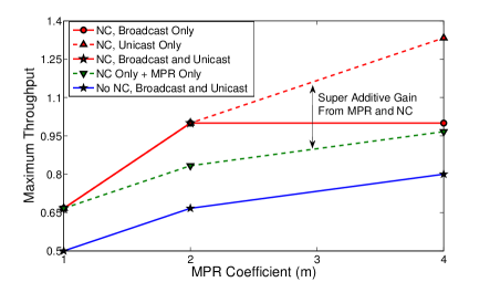
The use of the “X” topology component allows us to determine behavior that was otherwise masked in the cross component. It provided insight into the behavior of NC and MPR in sparser networks, methods in which to implement variants of COPE for broadcast traffic, and highlighted the super-additive gains from combining the two communication technologies. We can also look into variants of the cross and “X” components; but they are not discussed since they provide little clarification to the presentation of the model. In this example, however, these variants provide insight into the robustness of MPR and COPE’s throughput gains to topology changes.
IV Improving the MAC Fairness Protocol
The use of our model highlighted a major drawback to the use of the 802.11 MAC in multi-hop networks. The non-monotonic throughput behavior that is evident in Fig. 3 and 4 significantly reduces throughput as the offered load to the network increases. We now show how the model can be used to redesign the MAC so that we eliminate this sub-optimal behavior in the presence of NC, MPR, and their combination. Furthermore, we use the model to develop a MAC approach that provides fairness to flows rather than to nodes.
It is obvious from Section III that if we want to eliminate the non-monotonic saturation throughput behavior, we want to allocate more channel resources to the center node than the edge nodes. We choose to allocate resources proportional to the amount of non-self-generated traffic flowing through each node when the network saturates. While allocating fewer resources to flows originating at the center and more resources to flows originated at edge nodes yields even higher throughput, this approach ensures that each flow of information is given the same priority. The center node will be allocated more resources than each edge node in order to relay information; but it must also limit the amount of self-generated traffic so that it equals the average per-node non-self-generated traffic being relayed.
We design the revised MAC using a slight modification of the components found in Fig. 2. For the cross topology component, we let there be edge nodes and a single center, or relay, node. All edge nodes are connected with the center node and connected with all other edge nodes except the one directly opposite the center. For the “X” topology component, we also let there be edge nodes and a single center node. The edge nodes are split into two sets and . All edge nodes within a given set are fully connected and also connected to the center node. Within the cross topology component, each node communicates with the node directly opposite the center. In the “X” topology component, each node communicates with a node in a different set.
The allocated number of time slots each node receives so that the throughput is maximized, subject to the flow constraints and , is divided into three cases where is the fraction of time slots allocated to each edge node and is the fraction of time slots allocated to the center node. Similar to Section III, the throughput when NC is not used. When NC is used, is a function of the number of packets that can be coded together, which is dependent on the density of the network, the MPR coefficient , the use of CSMA, and the traffic type (unicast or broadcast). In order to simplify the explanation within this paper, we limit the examples we explore by considering only values of and symmetric source loads. In the case of the “X” topology component, we also restrict our example to situations where the cardinality of each set and are equal. The cases include:
Cross Topology Component with Unicast Traffic or Broadcast Traffic: The cross topology component can be used to design part of the MAC for operation in dense networks. Without NC, the center node requires a number of time slots equal to the number of source nodes . With NC, throughput is maximized by ensuring the center node codes the maximum number of native packets together. Implementing MPR for can potentially prevent each node from immediately decoding any coded message sent by the center. This is due to the potential of a given node transmitting at the same time as one of its neighbors. Generalizing for and as well as considering only integer numbers of time slots:
| (1) |
and
| (2) |
“X” Topology Component: Using the “X” topology component helps gain insight into the design of the MAC for operation in sparser networks. From the 802.11 example in Section III-B, we determined that the throughput differs for both unicast and broadcast traffic. As a result, we define the fraction of time slots allocated to each node for unicast traffic as:
| (3) |
and
| (4) |
When considering broadcast traffic, additional degrees of freedom may need to be sent by the center to complete the session. For , no additional degrees of freedom are required by any node. For the case involving NC and , each edge node will require one additional degree of freedom in order to decode all of the encoded packets sent by the center. As a result, the denominator in the NC equations of (3) and (4) is replaced by , as well as the numerator in the NC case of (4) with .
We apply the revised fairness protocol to both the 5-node cross and “X” topology components using the same methods described in Section III. We find that the throughput saturates at the maxima found in Section III for each topology component. Fig. 6 and 7 show both the unicast and broadcast throughput for the cross and “X” topology components, respectively, using our improved MAC approach. It is clear by comparing Figures 3 and 4 with Figures 6 and 7 respectively that the new MAC eliminates the non-monotonic saturation behavior. Furthermore, this comparison shows that the combination of NC, MPR with , and the new MAC provides throughput gains on the order of six times that of routing alone with the 802.11 MAC in the saturated throughput regime.
V Conclusion
We developed a simple, intuitive model by approximating key network elements with simple models of their underlying primary behavior. We then used the model to evaluate the performance of specific implementations of the 802.11 MAC with COPE and MPR in multi-hop networks. Gaining key insight into design strategies for combining the three technologies, each scenario presented gave a rough order of magnitude for the performance of implementing the MAC, NC, MPR, and their combination in larger networks. The model further shows that combining COPE with MPR results in super-additive throughput gains. We then demonstrated that the non-monotonic saturation experienced in [1] is explained by the sub-optimal behavior of the 802.11 MAC, and used our model to develop a MAC approach tailored toward the combined use of COPE and MPR that provides monotonic saturation behavior, as well as fairness to flows rather than nodes.
References
- [1] S. Katti, H. Rahul, W. Hu, D. Katabi, M. Médard, and J. Crowcroft, “XORs in the Air: Practical Wireless Network Coding,” IEEE/ACM Trans. Netw., vol. 16, no. 3, pp. 497–510, 2008.
- [2] F. Zhao and M. Médard, “On Analyzing and Improving COPE Performance,” Information Theory and Applications Workshop (ITA), 2010.
- [3] J. Le, J. Lui, and D. M. Chiu, “How Many Packets Can We Encode? - An Analysis of Practical Wireless Network Coding,” INFOCOM, 2008.
- [4] S. Sengupta, S. Rayanchu, and S. Banerjee, “An Analysis of Wireless Network Coding for Unicast Sessions: The Case for Coding-Aware Routing,” INFOCOM, 2007.
- [5] H. Seferoglu and A. Markopoulou, “Network Coding-Aware Queue Management for Unicast Flows over Coded Wireless Networks,” NetCod, 2010.
- [6] Q. Zhao and L. Tong, “A Multiqueue Service Room MAC Protocol for Wireless Networks with Multipacket Reception,” IEEE/ACM Transactions on Networking, vol. 11, no. 1, pp. 125 – 137, Feb 2003.
- [7] S. Ghez, S. Verdu, and S. Schwartz, “Stability Properties of Slotted Aloha with Multipacket Reception Capability,” IEEE Transactions on Automatic Control, vol. 33, no. 7, pp. 640 –649, Jul 1988.
- [8] G. Celik, G. Zussman, W. Khan, and E. Modiano, “MAC for Networks with Multipacket Reception Capability and Spatially Distributed Nodes,” IEEE Transactions on Mobile Computing, vol. 9, no. 2, pp. 226 –240, Feb. 2010.
- [9] L. Tong, Q. Zhao, and G. Mergen, “Multipacket Reception in Random Access Wireless Networks: From Signal Processing to Optimal Medium Access Control,” Communications Magazine, IEEE, vol. 39, no. 11, pp. 108 –112, nov 2001.
- [10] J. J. Garcia-Luna-Aceves, H. R. Sadjadpour, and Z. Wang, “Extending the Capacity of Ad Hoc Networks Beyond Network Coding,” IWCMC, 2007.
- [11] A. Rezaee, L. Zeger, and M. Médard, “Multi Packet Reception and Network Coding,” MILCOM, 2010.