Electrostatic stability of insulating surfaces: Theory and applications
Abstract
We analyze the electrostatic stability of insulating surfaces in the framework of the bulk modern theory of polarization. We show that heuristic arguments based on a fully ionic limit find formal justification at the microscopic level, even in solids where the bonding has a mixed ionic/covalent character. Based on these arguments, we propose simple criteria to construct arbitrary non-polar terminations of a given bulk crystal. We illustrate our ideas by performing model calculations of several LaAlO3 and SrTiO3 surfaces. We find, in the case of ideal LaAlO3 surfaces, that cleavage along a higher-index direction is energetically favorable compared to the polar (100) orientation. In the presence of external adsorbates or defects the picture can change dramatically, as we demonstrate in the case of H2O/LaAlO3(100).
pacs:
71.15.-mI Introduction
A uniformly charged plane separating two semi-infinite regions of space yields a divergent electrostatic energy; for this reason, polar surfaces or interfaces cannot exist. Goniakowski et al. (2008) Yet, thanks to recent progress in epitaxial growth techniques, nominally polar terminations of insulating crystals are now routinely prepared and characterized within well-controlled experimental conditions. Enterkin et al. (2010); Lauritsen et al. (2011) This is possible because, in practice, there are several mechanisms available for a polar surface to neutralize the problematic excess charge, and possibly become thermodynamically stable. These include adsorption of foreign gas-phase species, changes in the surface stoichiometry, ionic and/or electronic reconstructions, or local metallization via accumulation of intrinsic free carriers; each of the above can, in principle, prevent the “polar catastrophe” by restoring the correct charge balance at the surface.
Understanding and controlling these compensation mechanisms is a subject of great importance for many areas of fundamental science and technology. For example, surface polarity is of great interest for catalysis, gas sensing and energy applications Yun and Altman (2007); Levchenko and Rappe (2008), as adsorption and/or redox of gas-phase species are known to be strongly influenced by the electrostatic environment Garrity et al. (2010). In the context of perovskite-structure thin films and heterostructures, control of surface charge/polarity is currently investigated as a route towards the development of novel field-effect devices (e.g. in the LaAlO3/SrTiO3 system Cen et al. (2008); Xie et al. (2010); Son et al. (2010)), or ferroelectric memories based on the tunneling electroresistance effect García et al. (2009). Central to rationalizing all these phenomena is the intimate relationship between surface charge and bulk polarization in crystalline insulators, which was formally established by Vanderbilt and King-Smith in 1993. Vanderbilt and King-Smith (1993)
From the point of view of the theoretical analysis, it is crucial to establish an unambiguous criterion to classify a given surface as “polar-compensated” (i.e. an originally polar surface that was neutralized via one of the aforementioned mechanisms) or intrinsically non-polar. Goniakowski et al. (2008) This is not just a matter of nomenclature, but has very concrete practical relevance: non-polar terminations generally tend to be more stable, as extrinsic (i.e. not originated from the primitive building blocks of the insulating bulk crystal) sources of compensating charge tend to have a high energy cost. Furthermore, if a given surface is polar, one needs to know precisely how much external charge is needed to neutralize it; this greatly facilitates the theoretical analysis by restricting the number of possible candidate structures. We shall see in the following that, while the energetics is a genuine surface property, an exact answer to the latter question can be given already at the bulk level. Many authors have already addressed this issue in the past – we shall briefly mention hereafter the approaches that are most directly relevant to our work.
Tasker Tasker (1979) modeled a given ionic crystal as a lattice of point charges, corresponding to the nominal valence of the ions. Based on an abrupt truncation of this lattice, a given surface is then classified as polar on non-polar, depending on the behavior of the electrostatic energy. In particular, in the former (polar) case, the bulk repeated unit cell carries a finite dipole moment; this produces a diverging electrostatic potential unless compensated by an equal and opposite external surface charge density. This model, despite its simplicity, turned out to be surprisingly effective, and was able to correctly predict, at least at the qualitative level, the polar or non-polar nature of the vast majority of insulating surfaces. However, at the quantitative level this model has clear limitations. Many oxides and semiconductors display a marked covalent character, and the bulk polarization departs significantly from the value that can be inferred from atomic positions and nominal valence charges. Hence the need for a more accurate treatment.
To address these issues, and adopt a more realistic description of the charge density of the solid, Goniakowski et al. Goniakowski et al. (2008) proposed a different criterion for classifying surfaces as polar or non-polar. At the heart of the strategy of Ref. Goniakowski et al., 2008 is the concept of “dipole-free” unit cell. Given a certain plane orientation, one can demonstrate that it is always possible to choose a dipole-free repeated unit along the normal to that plane; then, the remainder charge that is left at the surface (once the bulk units have been removed) determines the polar or non-polar character of the termination. This criterion, however, is not free from ambiguities: for the same surface termination there may exist more than one possible choice of the dipole-free bulk unit cell, which might lead to opposite conclusions about the polar or non-polar character of the surface (see section II.7.2 for a detailed discussion). Also, identifying the dipole-free unit cell might be cumbersome in the case of higher index surfaces, where the structural complexity of the larger cell could complicate this type of analysis. Finally, the intuitive appeal of Tasker’s model is apparently lost in the strategy of Ref. Goniakowski et al., 2008: one needs to look at the ground-state charge density (e.g. as provided by a first-principles calculation) before drawing a conclusion.
There are two further issues that are common to both methods. First, it is universally agreed that the surface polarity is a property of the actual lattice termination. This means that, for a given material and surface plane orientation, there might be polar and non-polar terminations, depending on the surface stoichiometry. However, there is no established recipe to unambiguously decide, given a compound crystal and a surface orientation, whether a stoichiometric non-polar termination is allowed at all. Furthermore, it is not clear how to construct, in general, a non-polar candidate structure without relying on a heuristic counting of the layer charges. Second, it was correctly recognized by both Tasker and Goniakowski that the issue of surface polarity is directly related to the bulk polarization of the material. However, neither model traces a formal link to the modern theory of polarization in periodic insulators King-Smith and Vanderbilt (1993), where the macroscopic is a multivalued vector field, written in terms of the phases of the wavefunctions. Only the total charge density (modulus of the wavefunctions) is considered in the model of Ref. Goniakowski et al., 2008, while explicit electronic orbitals are not addressed by Tasker’s approach. Recent theoretical works have indeed highlighted the importance of the formal Berry-phase polarization in discussing polarity at surfaces Levchenko and Rappe (2008) and interfaces Stengel and Vanderbilt (2009), but a general formulation of the problem, based on the formalism established in Ref. Vanderbilt and King-Smith, 1993, is still missing.
Here we show that a Wannier function representation Marzari and Vanderbilt (1997); Stengel and Spaldin (2006) together with the “interface theorem” of Ref. Vanderbilt and King-Smith, 1993, provide a very natural framework for addressing the above issues. Wannier functions were already shown to be a very useful tool, in layered superlattices Wu et al. (2006, 2008), for partitioning the polarization of a crystal into the contribution of individual charge-neutral units. Most importantly, Wannier functions are intimately linked to the modern theory of polarization in solids Resta and Vanderbilt (2007), and therefore appear to be the most appropriate ingredient to discuss the issue of surface polarity, where the basic question concerns the existence of a finite dipole moment perpendicular to the surface plane. We shall provide, based on this description, precise criteria to establish whether truncating a bulk crystal along a given crystallographic orientation can yield a non-polar surface. We shall demonstrate that answering this question involves only an analysis of the bulk, and that our scheme naturally leads to candidate structures that can be used as a starting point for the subsequent determination of the thermodynamic ground state. To demonstrate our arguments, we focus on the surfaces of LaAlO3 and SrTiO3, two prototypical perovskite materials that have been at the center of the attention in the past few years as their polar (100) interface exhibits numerous peculiar properties.
This work is organized as follows. In section II we introduce our definition of polar surface and its formal relationship to the theory of bulk polarization. We also establish a direct link to Tasker’s model and we compare it to the “dipole-free” cell approach. In section III we apply this formalism to a variety of systems, including non-polar LaAlO3 and SrTiO3(111) surfaces. We also discuss electronic/ionic compensation mechanisms of polar LaAlO3(100). In section IV we briefly address some related topics, including the case of ferroelectric surfaces, and possible extensions to covalent semiconductors. Finally, in section V we present a brief summary and the conclusions.
II Theory
II.1 Definition of polar surface
In full generality, for the surface of a crystalline insulator to be electrostatically stable, it must have a vanishing density of physical surface charge, . In order to introduce the notion of surface polarity, it is useful to separate into two distinct contributions, and rewrite the stability condition as
| (1) |
Here is the bulk polarization, is the normal to the surface plane, and is a surface density of “external” compensating charges, which encompasses all contributions that cannot conveniently be described as “bulk-like” in nature (we include the latter in ). typically includes free charges (e.g. in the form of a confined electron gas) and/or bound charges (either in the form of surface adsorbates, vacancies, non-stoichiometric reconstructions, or non-isoelectronic substitutions).
We define a given surface as non-polar if the stability criterion Eq. (1) can be satisfied in the absence of external charges , which implies
| (2) |
This equation, at first sight, looks inconsistent with the current understanding of the surface polarity problem. It is now widely accepted that the polar or non-polar attribute is a property of the termination, not only of the material and surface plane orientation, contrary to what Eq. (2) seems to suggest. We shall see in the following section that the choice of the termination is only apparently absent from Eq. (2). It is implicitly included through the intrinsically multivalued nature of , which is a well-established aspect of the modern theory of polarization in bulk insulators. King-Smith and Vanderbilt (1993)
II.2 The bulk polarization
II.2.1 As a Berry phase
We consider a crystalline insulator described by three primitive translation vectors and a basis of atoms located at positions , with . The “formal” Resta and Vanderbilt (2007) bulk polarization is usually defined as
| (3) |
Here is the charge of the ionic core , is the (positive) electron charge and is the Berry phase King-Smith and Vanderbilt (1993) along the reciprocal-space vector ; for simplicity we assume spin pairing, hence the factor of in the electronic contribution.
It is important to note that , as defined in Eq. (3) is only defined modulo a “quantum of polarization”; in other words, it is not a single-valued but a multi-valued function of the electronic and structural degrees of freedom. This indeterminacy concerns both the ionic and the electronic parts in Eq. (3). On one hand, one has the freedom to choose any of the periodically repeated images of each atomic specie, and thus change by an arbitrary translation vector of the type . On the other hand, are phases of complex numbers, and therefore only defined modulo .
In the following sections we shall use the equivalent formulation of in terms of Wannier functions to illustrate the relationship between the multivaluedness of and the termination of the crystal lattice.
II.2.2 From the Wannier functions
We shall explicitly assume, from now on, a single-particle picture, in terms of a Kohn-Sham set of orbitals, and a conventional (as opposed to topological) insulating state. Within these assumptions, it is possible to express the electronic ground state of the bulk solid in terms of a set of maximally-localized Wannier functions Marzari and Vanderbilt (1997), which are exponentially localized in direct space Brouder et al. (2007). Based on this representation, Eq. (3) can be rewritten as
| (4) |
where is the total number of electrons in the primitive cell, and is the location of the center of the -th Wannier function.
Alternatively, we can think in terms of a charge density distribution that consists in the basis of atomic point charges together with the Wannier densities,
| (5) |
where is the -th Wannier function of the primitive cell. By construction, the sum of all the periodic images of “tiles” the total charge density of the extended solid. Then, by combining Eq. (4) and Eq. (5) one immediately obtains the intuitive connection to the Clausius-Mossotti formula,
| (6) |
where is the dipole moment of .
This formulation provides a transparent way to partition the total charge density into individual primitive units, whose dipole moment correctly yields the formal value of . In doing so, the phase indeterminacy of the electronic contribution to the polarization discussed in the previous Section has been reduced to a lattice indeterminacy, in all respects analogous to that characterizing the ionic contribution. In other words, all the complications related to the quantum-mechanical nature of the electrons have been mapped into a system of classical point charges, where the atoms and the electrons are formally treated on the same footing. In the following section we discuss how this Wannier representation can be further partitioned into smaller units that retain the chemical information about the formal oxidation state of each ion, which is central to the notion of “polar surface”.
II.3 Formal ionic charges
The location of the Wannier functions generally reflects the bonding properties of the material – in ionic solids they will cluster around the atoms, while in covalent materials they will tend to occupy the bond centers. We shall assume that the solid has at least a certain degree of ionic character, so it is possible to “assign” each Wannier function to a given atom without ambiguities; this is certainly true in most known oxide materials. (With some caution the ideas developed here can be conveniently adapted to any crystalline insulator; we shall briefly discuss the example of purely covalent semiconductors in Sec. IV.) We then combine each ion with the Wannier orbitals that “belong” to it and define a set of compound charge distributions that we call “Wannier ions” (WI),
| (7) |
(We operated a translation so that the nucleus sits in the origin.) As the Wannier function locations usually agree remarkably well with chemical intuition, each of these charge distributions will carry a monopole corresponding to the “nominal” charge of the ion (e.g. for O, for Sr, for Ti). In addition to their net charge, the WI are non-spherical and generally carry non-zero dipole moments . (Higher multipoles are also present, but are not directly relevant for the present discussion.) can now be rewritten in terms of the WI densities,
| (8) |
which is equivalent to Eq. (5) except that here we use precautions to keep the basic WI units intact. It follows that the dipole moment of can be written in terms of two contributions,
| (9) |
The first term is the dipole moment of a system of point charges located at positions ,
| (10) |
The second term is the sum of the individual dipole moments of the WI,
| (11) |
It is possible to show that is a single-valued, gauge-invariant quantity; this number contains all the non-trivial electronic contributions to the polarization that are due to the deformation of the ionic orbitals in the crystalline environment. The gauge invariance of might be surprising at first sight, as the individual dipole moments are manifestly gauge-dependent, i.e. they depend on the specific algorithm used to localize the Wannier functions. This arbitrariness cancels out when all are summed up, as long as the assignment of each Wannier function to a specific lattice site remains unambiguous. This is equivalent to stating that a given choice of uniquely determines the branch choice of the electronic polarization, which is a reasonable assumption in ionic materials where the nature of the valence wavefunction has typically a marked atomic character.
With this new decomposition of , we have overcome an important drawback of Eq. (4) and Eq. (3): in the latter two equations the decomposition of into ionic and electronic contributions is physically meaningless – only the sum of the two terms is well defined. Here both and are formally meaningful objects. All the indeterminacy in the definition of has been recast into the term , which has an intuitive interpretation as the dipole moment of a system of classical ions, each of them carrying its formal valence charge. The term which contains the quantum-mechanical information about the electronic polarization effects is now , which is now a single-valued quantity; this has also a simple physical interpretation as the total dipole moment of the electronic clouds of the WI.
Before closing this part, it is useful to point out a direct relationship between our formalism and the “layer polarizations” (LP), , introduced in Refs. Wu et al., 2006 and Wu et al., 2008. If one is interested in layered perovskites with stacking axis along the (001) direction, it is useful to consider a decomposition of the charge density of the ABO3 cell into individual AO and BO2 layers. In the framework of the present work this implies grouping together the WI that belong to a given oxide layer. In particular, the total charge density of each layer can be then written as a sum of all WI densities that belong to layer ,
| (12) |
In II-IV perovskites the layers are formally charge-neutral Wu et al. (2006, 2008). then carries a well-defined dipole moment, which is directly related to the LP,
| (13) |
(The bar indicates in-plane averaging, and the integral is carried out along the stacking axis; is the cell cross-section.) We shall illustrate this layer-by-layer decomposition of the total charge density with practical examples in section II.7.2.
II.4 Crystal termination as a bulk property
We shall illustrate in this section that the multivaluedness of the term can be formally related to the surface termination of a semi-infinite crystal. This fact is not new, and was rigorously established within the modern theory of polarization Vanderbilt and King-Smith (1993). Here we discuss the implications of the “interface theorem” for the electrostatics of polar surfaces.
Following Goniakowski et al. Goniakowski et al. (2008), we define a frozen bulk termination as a surface that is obtained by piling up “bulk unit cells” without any further electronic or ionic relaxation. For the time being, we shall limit our discussion of surface polarity to this (somewhat unrealistic) type of surface, that we further specify hereafter; we shall make the link to more realistic surface models in the next section. In contrast with Goniakowski et al. Goniakowski et al. (2008), here we define our “bulk unit cell” as a charge density distribution that results from a superposition of bulk WI, as in Eq. (8). Then, we construct the charge density distribution of the semi-infinite surface system as a superposition of ,
| (14) |
where is a real-space translation vector, and again is the normal to the surface plane. This way of defining a frozen bulk termination has two crucial advantages: (i) The choice of using the compound WI as our “elementary particles” naturally ensures that every ion in the surface system will have exactly the same formal oxidation state as in the bulk. This is a central point in the definition of a polar surface – if we allowed for fractional orbital occupations no surface would be polar. (ii) The choice of cleaving the Bravais lattice, rather than the crystal lattice is particularly advantageous, as it naturally preserves the bulk stoichiometry everywhere in the system (if we allowed for stoichiometry changes of reconstructions again the notion of polar surface would be inconsistent).
It can be easily verified that several types of unreconstructed surfaces can be generated by using Eq. (14), simply by changing the definition of . In particular, we have the freedom to construct in many different ways, simply by shifting each WI in the basis by an arbitrary Bravais lattice vector . Thus, the choice of the basis vectors uniquely determines the surface structure, according to Eq. (8) and Eq. (14). (Of course, different choices of can lead to the same termination; the “ termination” relationship is a many-to-one function.) On the other hand, we have shown in the previous section that the choice of uniquely determines the value of , out of the infinite possibilities allowed precisely by the arbitrariness in the choice of the basis vectors. This formally establishes the relationship between and the termination of the lattice. By construction, the physical net charge that lies at the surface of a frozen bulk termination as defined above is simply , where is the dipole moment (per unit volume) of an appropriate bulk unit cell, i.e. one that tiles the semi-infinite solid according to Eq. (14).
Within these assumptions, we define a frozen bulk termination polar if the bulk building block used to construct it has a net dipole perpendicular to the surface plane; we define it non-polar otherwise. The problem of determining whether a surface is polar or not is, therefore, reduced to the problem of calculating the dipole moment of a bulk unit cell made of WI. This, in turn, can be directly related to the result of a Berry-phase calculation in the bulk crystal, which can be routinely performed with most publicly available codes. In other words, the termination itself can be understood as a bulk property.
II.5 Frozen and relaxed surfaces
It might appear artificial to consider surfaces that are constructed by stacking electronic orbitals corresponding to bulk Wannier functions. At a real surface, electronic states always depart from their bulk counterparts because of the peculiar chemical and electrostatic environment produced by the truncation of the crystal. Furthermore, also the ionic lattice undergoes nontrivial structural relaxations in the surface layers, in response to the perturbation of the bonding network. A central point of our formalism is that both (electronic and ionic) surface relaxation effects are essentially irrelevant in the context of deciding whether a given surface is polar on non-polar. As a matter of fact, either type of relaxation only affects the surface dipole moment, and not the surface charge density. Thus, genuine surface properties (e.g. the alignment between the bulk bands and the vacuum levels, or the surface energy) certainly depend on these mechanisms, but the polarity (which depends only on the physical surface charge) won’t be affected. This formally establishes the surface polarity as a property that can be completely understood at the bulk level – note that the termination dependence can also be understood as a bulk property as specified in the previous section. Then, all mechanisms that alter the surface charge (either in the form of a local composition change or as a modification of the formal oxidation state of the surface ions) are unambiguously understood as external compensation effects, and enter the definition of .
II.6 Construction of arbitrary non-polar terminations
So far we have addressed the question of deciding whether a given surface, of a certain orientation and termination, is polar or non-polar. One could wonder now, for a given bulk compound, (i) whether non-polar terminations can be constructed at all; (ii) if yes along which surface plane orientation; finally, it would be helpful to (iii) identify candidate non-polar surface structures based only on bulk information. In this section we shall illustrate how this is done within the present definition of surface polarity.
Essentially, the question (i) boils down to finding all possible values of . This is, within the modern theory of polarization, a periodic lattice of points. The difference between two arbitrary values of is a multiple of a real-space primitive translation vector,
| (15) |
Here is an integer times the electron charge . , which determines the resolution of the mesh depends on the convention of how the Wannier functions and the ion cores are grouped together. In particular, the constraint adopted here of assigning each Wannier function to a specific ionic site generally restricts the lattice of possible values of to a subset of those allowed by Eq. (4) and Eq. (3). This can be understood by observing that the new elementary building blocks of the lattice are the “compound objects” WI, rather than single electrons or ions.
Answering question (ii) consists in finding the intersections between the infinite lattice of values and a given surface plane, which is a straightforward geometrical problem.
Answering question (iii) then is easy by recalling the direct relationship between a given value of and the dipole moment of a well defined bulk unit. More specifically, once a value (or a subset of values) of is found for which , models of the non-polar surface can be readily built by stacking [using Eq. (14)] bulk unit cells that correspond to those same values of . We shall present several practical examples of this strategy in Sec. III.
II.7 Relationship to previous approaches
II.7.1 Tasker model
Eq. (9) constitutes the rigorous link between Tasker’s model Tasker (1979) and the modern theory of polarization in periodic insulators. Within our formalism, the total excess charge at a frozen bulk termination can be exactly written as
| (16) |
where the sum is extended over all atoms in the semi-infinite crystal. The only difference between Tasker’s model and Eq. 16 is the additional, purely electronic contribution , which comes from the polarization of the Wannier ions in the crystalline environment. This contribution vanishes in all solids that are characterized by a center of symmetry; in these materials the discussion of the surface polarity problem in terms of nominal charges is therefore rigorous and exact. Even in materials where , neglecting this term is usually not crucial to assessing the polar or non-polar nature of a given surface. However, considering the WI contribution is essential for a quantitative estimation of (which is the excess charge that needs to be compensated); this is especially true in ferroelectric materials, which generally have a large anomalous contribution to . Thus, our formalism provides a formal justification to Tasker’s model, and completes it by introducing an additional well-defined electronic dipolar contribution, .
In addition to this, our strategy has important practical advantages. Tasker’s approach involves a direct calculation of Eq.(16) by means of an infinite lattice sum, whose convergence is ensured by using Ewald summation techniques. This procedure might be cumbersome in practice, and it requires a specialized computer code to perform the calculation. Our strategy greatly simplifies the problem, by reducing it to the calculation of the dipole moment of a small set of point charges. This can be done with paper and pencil in few minutes for a surface of arbitrary orientation, provided that one knows . This vanishes in many cases of practical interest – whenever it doesn’t vanish, only a single bulk Berry-phase calculation is needed to evaluate this contribution. Moreover, our strategy allows one to easily answer a number of physical questions that were difficult to address within Tasker’s approach, e.g. those discussed in the previous section.
II.7.2 Other approaches
In order to fully appreciate the advantages of our formalism, it is useful to compare it, in a practical case, with the alternative notion of “dipole-free unit cell” proposed by Goniakowski et al. Goniakowski et al. (2008) For illustrative purposes, we consider the (100) surfaces of two prototypical perovskite materials, LaAlO3 and SrTiO3, in their cubic high-symmetry phase. We shall use either the arguments developed in the previous sections, based solely on bulk properties of the respective materials, or the theory of Ref. Goniakowski et al., 2008, in order to assess the polar or non-polar character of these surfaces.
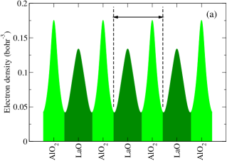
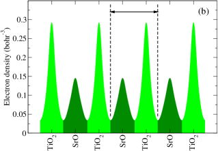
In Fig. 1 we plot, along the (001)-oriented axis, the -planar average of the total valence charge density. (The left panels refer to LaAlO3, the right ones to SrTiO3.) The upper panels show a possible decomposition of the electronic charge that leads to a dipole-free unit cell, which we construct as follows. First, we count the total charge of the ionic cores of the individual oxide layers. With the pseudopotentials used in this work, these are LaO(+17), AlO2(+15), SrO(+16) and TiO2(+24). Next, we decompose the total valence charge by cutting it with abrupt (001) planes located in the interstitial regions. The location of those planes is chosen as to (i) respect the inversion symmetry of the crystal, and to (ii) assign to each layer an electron density that exactly cancels the positive core charge of that layer. The resulting electron charge assigned to the AO layers is highlighted with a dark shading (light for the BO2 layers). By construction, the “unit cell” obtained by combining two adjacent layers (evidenced by the arrow and dashed lines in the figure) has zero dipole moment in both LaAlO3 and SrTiO3. Hence, this construction fails at detecting any fundamental difference between LaAlO3 and SrTiO3: both are predicted to have non-polar (001) surfaces. Of course, this prediction relies on a completely arbitrary partition of the total electronic charge density. There are many other ways to do it. For example, if one chooses a different location of the cut planes (e.g. at the mid-point distance between the atomic planes), or yet a more sophisticated prescription (e.g. based on the Bader analysis), one generally gets a non-vanishing layer charge in both LaAlO3 and SrTiO3. From this perspective, one would have to conclude that the (001) surfaces of both materials are polar. The main point that we want to stress here is that, if we base our analysis solely on the total electronic density [as we have done in Fig. 1(a-b)], (i) the choice between one partitioning scheme and the other is arbitrary; (ii) any statement about the surface polarity inferred from such a partitioning is ambiguous; and (iii) such an analysis cannot be linked in any ways to the bulk polarization of the material (the latter cannot be defined, even in principle, in terms of the total charge density of a periodic crystal).
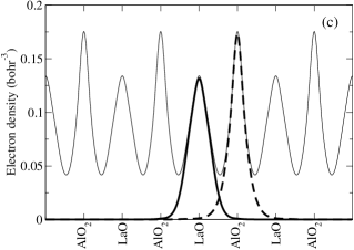
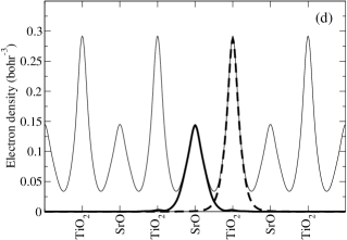
In Fig. 1(c-d) we demonstrate how the Wannier-based decomposition of the valence density solves this problem. The thin solid lines show, as above, the ground-state electronic charge densities (again, the bar symbol on indicates that an in-plane averaging was performed). The total Wannier densities of each layer, defined as in Eq. (12), are shown as thick lines (solid for the AO layers, dashed for the BO2 layers). Note that we show the electron density as positive, and we omit the bare pseudopotential charges from the plots. (These are a lattice of Dirac delta functions, centered at the oxide layer locations.) As the Wannier functions are discrete objects, the total electronic charges are integer numbers. Most importantly, the Wannier functions carry some crucial information (that is absent in the total valence density) on how the localized bound charges are organized in the insulating state of each compound. It turns out that (summing up the contributions from the cores) the LaO and AlO2 layers have a total charge of +1 and -1, respectively, while the SrO and TiO2 layers result charge-neutral, in perfect agreement with the naive assumption of perfect ionicity. Thus, the Wannier decomposition correctly identifies LaAlO3(001) as polar and SrTiO3 as non-polar, in agreement with Tasker’s classification.
To corroborate our arguments, a further consideration is in order. One could be tempted to criticize our reasoning by observing that Wannier functions are by no means uniquely defined starting from a given set of Bloch orbitals. In Fig. 1(c-d) we have chosen a maximally localized Marzari and Vanderbilt (1997) representation, but there is nothing really fundamental behind this choice. Is the identification of a surface as polar or non-polar robust against this arbitrariness? The answer is yes. The formal proof of this statement was derived in 1993 Vanderbilt and King-Smith (1993), several years before the maximally localized Wannier functions were first introduced. Our choice of a maximally localized representation is motivated by its intuitive relationship to elementary chemical concepts (e.g. formal valence), but the reader should keep in mind that this is just a convenient way of expressing a concept that has solid mathematical grounds. In particular, the exact value of the surface charge can be computed at the bulk level, regardless of the degree of ionicity of the material. Vanderbilt and King-Smith (1993)
III Application to perovskite surfaces
III.1 LaAlO3 and SrTiO3: bulk properties
We now use two prototypical perovskite materials, LaAlO3 and SrTiO3, to illustrate our strategy in practice. This choice of materials is motivated by the recent discovery of a conducting electron gas at their polar (100) interface. Ohtomo and Hwang (2004) This has generated a lively excitement in the research community and a renewed interest in the theoretical foundations of the surface/interface polarity problem. Higuchi and Hwang (2008); Bristowe et al. (2011); Stengel and Vanderbilt (2009)
We shall address questions (i-iii) raised in Sec. II.6. For simplicity, in both materials we consider only surfaces of the type (0ij). This means that only the projection of on the plane is relevant, and our procedure can be conveniently represented on 2D graphs. Our strategy is general, and this choice was made only to simplify the notation and the graphical representations. We also consider both bulk compounds within their high symmetry cubic phase. (Both materials are characterized by zone-boundary distortions, related to rotations and tilts of the oxygen octahedral network; however, as these distortions are non-polar in nature, they are irrelevant for the present discussion.)
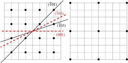
To start with (question i), we need to find the lattice of “allowed” values of in either material. Recalling that both compounds are characterized by a center of symmetry, it follows that , and is exactly determined by the formal valence charges of the participating ions, all sitting in their high-symmetry lattice sites. Now, the formal ionic charges are La(+3), Al(+3) in LaAlO3, Sr(+2), Ti(+4) in SrTiO3; oxygens in either compound have a formal charge of (-2). In Fig. 2 we show how different choices of the crystal basis of five atoms lead to different dipole moments per unit cell, and hence to a different formal polarization. If we could take all (infinite) combinations, we would obtain an infinite lattice of points, which is isomorphic with the real-space Bravais lattice of the cubic crystal. The 2D projection of the lattice of in either compound is shown in Fig. 3. Even if the two compounds are isostructural (recall that we consider both LAO and STO in their cubic phase), there are two important differences in their formal polarization lattice. First, is centered in the origin, while is centered in . Second, has a coarser mesh than – the spacings are doubled because the constituent point charges are all even in the former. Note that both lattices are centrosymmetric, consistent with the absence of a spontaneous polarization in either material. Resta and Vanderbilt (2007)
To answer question (ii), we need to find all possible intersections between a surface plane and the allowed values of ; the projection of a few representative surface planes are plotted in Fig. 3(a). As it can be readily appreciated from the diagram, the aforementioned qualitative differences between the respective lattices of STO and LAO have important consequences on the electrostatics of the surfaces. In particular, in STO the origin belongs to the allowed values of , and any surface plane intersects the origin by construction; therefore, a non-polar surface of any possible orientation can be readily constructed [we shall illustrate the case of STO(111) in Sec. III.3]. Conversely, in LAO only specific plane orientations intersect the lattice [note that the (100) orientation is correctly classified as polar]. In the following Section we shall consider a subset of these (infinite) possibilities, i.e. the vicinal surfaces, where is an arbitrary odd integer number. We shall focus on the lowest-index cases with .
III.2 Vicinal LaAlO3 surfaces
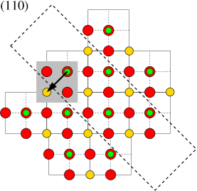
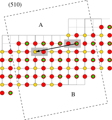
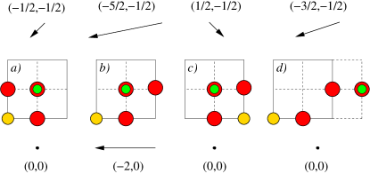
We first construct preliminary models for the surfaces with . These are obtained by using slab geometries, within the supercell method. First we choose a unit cell with the appropriate translational periodicity in plane, and enough room along the out-of-plane direction to accommodate both the slab and a vacuum region (slab and vacuum thicknesses are treated as convergence parameters). Second, we tile the slab region with repeated copies of a well-defined primitive basis of atoms, which is chosen in a such a way that its dipole moment lies exactly parallel to the surface plane. (This implies that the choice of the basis depends on the surface orientation.) This procedure leads to the slab models sketched in Fig. 4.
| Surface type | Surface orientation | ||
|---|---|---|---|
| (011) | (013) | (015) | |
| A | 1.93 | 2.23 | 2.15 |
| B | 1.93 | 1.85 | 1.83 |
| Cleavage | 3.86 | 4.08 | 3.98 |
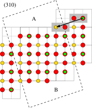
The first observation is that all these surface models [except maybe the (011) case] present alternating LaO-type and AlO2-type terraces, and these terraces tend to grow wider and wider for increasing . Note that [again, with the only exception of the (011) case], the construction described above produces, in fact, two inequivalent surface structures for each orientation. In other words, the models of Fig. 4 do not enjoy inversion symmetry. We shall refer to these two surfaces as “type A” and “type B”, where type A presents LaO-type step edges and type B has AlO-type edges. Remarkably, it is easy to realize that one can change from A-type to B-type simply by displacing an oxygen atom from one step edge to the neighboring one. This way, starting from the “mixed” AB-type slabs Fig. 4 one can readily construct pure AA or BB slabs. One can verify that the resulting AA and BB models do enjoy inversion symmetry. Since going from A to B preserves the bulk stoichiometry, this allows for a rigorous definition of the surface energy for all individual surface structures.
In practice, in the simulations we use a slab thickness of approximately 4-5 LAO cells in each case, which is more than sufficient to obtain a well-converged value of the surface energy. The surface energy is defined as
| (17) |
where and are the relaxed total energy of the slab supercell and of LAO bulk, is the total number of LAO units in the slab model, and is the surface area in each case ( is the lattice parameter of cubic LAO; the factor of 2 takes into account the fact that a slab has two surfaces). In Table 1 we report the results. Comparing these values with previous literature studies is difficult, as studies of vicinal perovskite surfaces are scarce. Only the lowest-index (011) surface type has been investigated to some extent, although we weren’t able to find data specific to LAO. Concerning other perovskite materials, Eglitis and Vanderbilt Eglitis and Vanderbilt (2008) reported an energy of 1.52 J/m2 for an isostructural O-terminated SrTiO3(011) surface structure. The value we obtain for LAO, 1.93 J/m2, is somewhat larger but otherwise of comparable magnitude. Note that in the study of Ref. Eglitis and Vanderbilt, 2008 a different (hybrid) functional was used – LDA might well overestimate surface energy values due to the well-known overbinding issues.
It is interesting to note that in the case of B-type surfaces the energy decreases slightly for increasing index . We ascribe this behavior to the lower steps-to-terraces ratio in the (013) and (015) surfaces (undercoordinated step sites are likely to be less favorable). We consider it unlikely, however, that this energy be further reduced for . Increasing would lead to larger and larger terraces that are locally charged [either of the LaO(+) or AlO2(-) type], and the electrostatic cost (roughly linear in ) would eventually dominate over the step energy (proportional to ) in a way that bears many analogies to Kittel’s theory of domain walls. Still, the increased stability of the vicinal (013) and (015) surfaces [compared to the (011) orientation] suggests that these geometries could be, in principle, fabricated under appropriate experimental conditions. The simultaneous presence AO and BO2 domains appears promising for applications, e.g. in selective self-assembly of functional nanostructures, as it was recently shown in the case of SrTiO3 Bachelet et al. (2009)
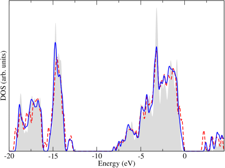
The above considerations on the energetics haven’t answered an important question yet: how can we verify that these surfaces are indeed non-polar, consistent with our predictions? A useful indication comes from the density of states. If a surface is polar, then there is a need for compensation via additional charge carriers (either electron or holes) that deplete or populate the energy bands of the crystal in proximity of the problematic termination. This typically results in a metallic surface. Conversely, if the surface is non-polar, the bulk-derived Wannier functions alone are sufficient to ensure electrostatic stability, and therefore the system can remain insulating. In Fig. 5 we show the total density of states extracted from a (013) (A- or B-type) slab model, compared with the bulk LAO density of states. In all cases there is a wide gap separating the unoccupied from the occupied states. This fact, together with the inversion symmetry and perfect bulk stoichiometry of the slabs, directly demonstrates that the surfaces are non-polar, and that every atom contributes with a total number of electrons that exactly corresponds to its formal ionic valence. Similar considerations apply to the (110) and (510) surface models (not shown).
It is important to stress that, contrary to a common misconception, all these surfaces are perfectly stoichiometric by construction, and they are non-reconstructed as they have the highest possible translational symmetry that is allowed by each plane orientation. It is often assumed that the only “legitimate” structures that can be named frozen bulk terminations are those that are obtained upon cleavage of the crystal lattice, i.e. preserving the integrity of the bulk-like atomic planes. This is, however, just a convention that has nothing fundamental to it. We believe it is more practical to truncate the Bravais lattice instead. This automatically preserves stoichiometry and translational symmetry, and dramatically simplifies the description of surface electrostatics.
As a final remark, it is fairly easy to realize that all the surface models presented in this section are non-polar for any non-ferroelectric perovskite material (or for a ferroelectric one in its high-temperature symmetric phase). This can be simply understood by observing that, by replacing the cations in each bulk primitive basis (see Fig. 4) with those of a different charge family (i.e. I-V or II-IV), the dipole moment changes its magnitude but not its direction. Also, all the surface models enjoy inversion symmetry and have ideal bulk stoichiometry – the absence of a dipole moment normal to the surface plane is therefore automatically guaranteed. Therefore, many of the considerations made here in relationship to the specific LAO case are actually completely general, and apply to all cubic perovskite compounds.
III.3 Non-polar SrTiO3(111) surfaces
To further illustrate our arguments, we move now to the case of SrTiO3. According to our definition of polar surface, and by observing that the simplest choice of the SrTiO3 bulk unit has zero dipole moment, one would conclude that in SrTiO3 any surface orientation is “non-polar”. To illustrate this point we shall consider here the (111) surface, which has been classified as polar by most authors. Note that this surface is indeed polar if one insists on terminating the crystal lattice with either a Ti or a SrO3 layer. Our prescription of cleaving the Bravais lattice and tiling it with well-defined bulk-like formula units is less restrictive, and allows for non-polar terminations as we shall see in the following.
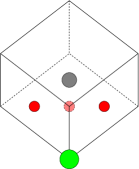
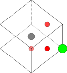
We build two inequivalent stoichiometric slab models (that we call A and B) by stacking the primitive building blocks schematically shown in Fig. 6. It is easy to verify that both choices of the primitive cell have zero dipole moment. (Again, to compute the dipole moment we use the formal charges. This is substantiated by the Wannier-based decomposition described in section II, which provides the formal link to the theory of polarization in bulk solids. King-Smith and Vanderbilt (1993)) The primitive translation vectors of the supercell are (in units of the bulk equilibrium lattice parameter a.u.) , and ; the out-of-plane spacing was chosen in order to include a sufficiently thick vacuum region separating the repeated images of the 10-layer slabs. As the slabs do not enjoy inversion symmetry (there are a total of four inequivalent surfaces in our simulations), we apply a dipole correction in the vacuum layer to avoid unphysical macroscopic fields in the bulk region of the SrTiO3 films. We use a regular -centered -point mesh to sample the surface Brillouin zone, and we fully relax our structures within the symmetry constraints allowed by the surface composition. Note that the A-type slab preserves the point group of the bulk (111) orientation, while the B-type slab has a lower symmetry due to the presence of an incomplete oxygen plane on one side.
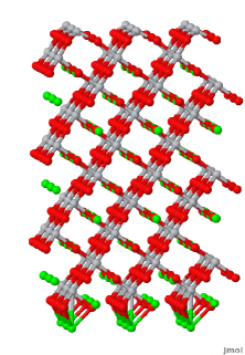
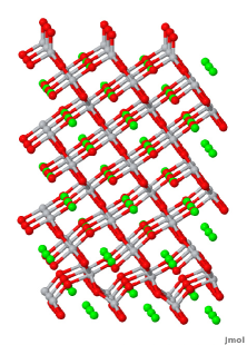
In Fig. 7 we show the relaxed structures of the two slab models described above (the primitive unit of the supercell was repeated three times in both in-plane directions to obtain a clearer view of the structure). Henceforth we shall indicate A1, A2, B1 and B2 the four inequivalent surfaces, where A and B refer to the specific slab model, and 1/2 refer to the top/bottom surface, respectively. A1 has a TiO3-type termination (i.e. an ideal Ti-type surface where the Sr atom has been removed from the topmost SrO3 layer), and correspondingly A2 contains a Sr-type termination, where undercoordinated Sr atoms protrude from the underlying oxygen group. B1 has a supplementary O atom accommodated on top of an ideal Ti-terminated surface, and this atom forms a tetrahedron surrounding the topmost Ti atom. B2 has an O vacancy in the terminating SrO2 layer; model B can be therefore obtained from model A simply by displacing a neutral SrO unit from the 2 (bottom) to the 1 (top) surface. Most of these surfaces were already considered in Ref. Marks et al., 2009, and indicated as “small unit-cell reconstructions” of SrTiO3(111). We note that surface reconstructions are typically associated with a reduction in the translational symmetry group, which is not the case for any of these models. Therefore, we rather regard these as primitive, stoichiometric bulk terminations. Whatever is the nomenclature, the authors of Ref. Marks et al., 2009 correctly recognized the formal charge neutrality of these “valence-compensated” terminations.
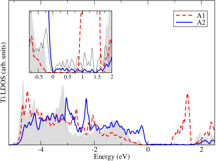
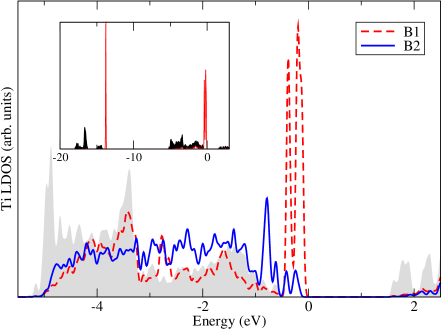
Similarly to the LaAlO3 case, we analyze the electronic properties of these surface models to verify their insulating character. We plot in Fig. 8 the local density of states (LDOS) integrated on spheres of radius 3.0 bohr surrounding the Ti atoms. In the main panels we show the average Ti LDOS in the middle of the slab (gray shaded areas), which we take as our bulk-like SrTiO3 reference curve. We also show the LDOS corresponding to the outermost Ti atom at the top (red dashed curve) and bottom (solid blue curve) surfaces. At A1 the gap is smaller than in the bulk, as a narrow band of Ti-derived unoccupied orbitals splits from the conduction band. The band gap narrowing is rather extreme at A2, where a highly dispersive surface state makes the gap as small as 0.1 eV at the point (presumably this free-electron-like state is originated from the and state of the protruding Sr ions). To better illustrate this, we show a blowup of the LDOS in the inset. Here we also plot (thin black curve) the LDOS of the outermost Sr atom, where the surface state has its maximum weight. The nearly flat DOS (the wiggles are caused by the finite resolution) between 0 and 1.5-2 eV, typical of a parabolic band in 2D, is clear. The B slab presents, overall, an energy gap which is much closer to the bulk value; this suggests that the system is electronically more stable than in A. Both at B1 and B2 the gap reduction is caused by valence-band derived surface states; these are reminiscent of the states that are found at some BO2-terminated (100) perovskite surfaces. Conversely, no conduction band-derived states are present. Especially interesting are the sharp peaks appearing at B1; these are derived from the atomic-like orbitals of the outermost O atom. To illustrate this point, we plot in the inset the LDOS on the terminating O, which lies at the vertex of the surface tetrahedron surrounding Ti; for comparison, we also show the LDOS of a bulk-like oxygen far from the surfaces. The - and the - derived features of the surface O appear extremely sharp and atomic-like, in contrast with the substantial broadening in the SrTiO3 bulk caused by band dispersion. A tetrahedral coordination might look unusual for Ti, which tends to adopt octahedral coordination in most (if not all) stable bulk oxide phases. Nevertheless, at the SrTiO3 surface, analogous tetrahedral units were recently shown both experimentally and theoretically to be energetically favorable, Enterkin et al. (2010) even in the case of the (110) orientation where there exist alternative structures with relatively low energy. Eglitis and Vanderbilt (2008)
Finally, we shall comment on the relative energy of these structures. Unlike the models discussed in the previous section, here it is not possible to construct a stoichiometric and symmetric slab; therefore, we can only calculate a cleavage energy for A and B, . Resolving this value into the contributions of the top and bottom terminations would require further considerations about the chemical potential of Sr, Ti and O; this goes beyond the scopes of the present work. We find (A)= 6.27 J/m2 and (B)= 3.94 J/m2. These values are both larger than the previously reported cleavage energies along the (100) or (110) directions. Especially the A model has a high energy cost, consistent with the “open” nature of the low-coordinated surface sites, and with the relatively unfavorable electronic configuration discussed in the previous section. Model B, on the other hand, has a cleavage energy that is significantly smaller, and (on average) reasonably close to typical (110) surface energies. It should be kept in mind that the cleavage energy might be unequally distributed between the B1 and B2 surfaces – we cannot exclude that one of the two might be quite stable in a wide range of thermodynamic conditions. (B) can be directly compared to the values reported in Ref. Marks et al., 2009, where it appears to correspond to the sum of the surface energies of model 3 and 4. The authors of Ref. Marks et al., 2009 did not use LDA but a variety of different density functionals, with values ranging from 4.94 eV (PBE) to 6.41 eV (TPSSh) per surface cell. Our LDA value of 6.31 eV per surface cell compares favorably with the highest value reported there, consistent with the systematic tendency of LDA towards overbinding.
It is interesting to compare our calculated (A)=10.0 eV/cell to the energy associated with the “textbook” cleavage, i.e. that leaving atomically flat, metallic and polar Ti / SrO3 terminations. Assuming that our LDA values are comparable to the TPSSh results of Marks et al., we can infer the Ti / SrO3 cleavage energy by summing up the TPSSh surface energies of model 1 and 2 in the aforementioned work; this yields a value of 12.3 eV / cell. As surprising as it may sound, our non-polar cleavage model A, with the severely undercoordinated Sr atoms protruding from surface A2, is still about 2 eV /cell lower in energy than the atomically flat cleavage model. This fact highlights the importance of achieving electrostatic stability from bulk-like building blocks, without invoking external compensation mechanisms (such as hole or electron doping as in the case of Ti / SrO3).
III.4 Polarity compensation of LaAlO3(100)
So far we restricted our analysis to ideal non-polar surfaces, i.e. systems where only bulk-like building blocks are present. To complete our discussion we now consider a prototypical polar surface, LaAlO3(100), and illustrate how our arguments apply to the analysis of selected compensation mechanisms, where we introduce extrinsic sources of compensating charge .
III.4.1 Via metallic carriers
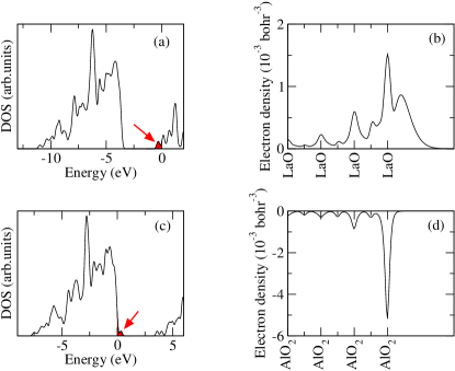
First, we consider the clean LaO- and AlO2-terminated (100) surfaces. Due to the built-in dipole of the bulk unit cell that we must use to construct these terminations, there is an excess charge of and per surface unit cell, respectively. If we don’t relax the translational symmetry, the only possible compensation comes from metallic carriers, either in the form of conduction band electrons or valence holes. By performing two separate calculations of symmetrically terminated 6.5-unit cell thick slabs, we indeed obtain metallic surfaces. In Fig. 9 we plot the total density of states for both slabs, where the Fermi level clearly crosses either the valence band (AlO2 termination) or the conduction band (LaO termination).
An interesting feature of the DOS of Fig. 9(a-c) is that, in both cases, a clear gap persists in the spectrum. This means that, in spite of the partial metallization, the conduction and valence bands preserve their respective identities. This observation implies that we can rigorously separate what we consider “bound charges” (which are all of bulk origin here, as we don’t introduce extrinsic species in the supercell) from “external compensating charge”, following the prescriptions of Ref. Stengel et al., 2011 and Stengel, 2011. The former, which we take as the total charge density of the (completely filled) valence-band manifold, are implicitly included in the definition of ; the latter can be either a positive external density of valence-band holes (ext,h) or a negative density of conduction-band electrons (ext,e),
| (18) | |||||
| (19) |
Here is the planar-averaged and energy-smeared local density of states defined in Ref. Stengel et al., 2011, and is the Fermi level. The electronic states that contribute to the integrated charge densities and are evidenced as shaded areas in the DOS plot of Fig. 9. (Note that the DOS is the volume integral of .) In Fig. 9(b-d) we plot the compensating surface densities and . Both appear localized to the surface region, although they display a relatively slow decay into bulk LaAlO3, and amount (within machine precision) to a total of exactly plus or minus half an electron per side. This demonstrates the full consistency [in the sense of Eq. (1)] between the “external charge” defined in Eq. (19) and (19), and the prediction of excess bound charge coming from the analysis of . Note that, in the case of the LaO-terminated slab, part of the charge spills out into the vacuum region. This is a consequence of the vacuum level being very close to the conduction band edge, which is populated by the compensating electrons. Conversely, only O()-derived states contribute to . By combining the total energies of the reference slabs and subtracting an appropriate number of bulk reference units, we obtain a relaxed cleavage energy of 4.53 eV per surface cell (5.13 J/m2). This is larger than the cleavage energies we computed in Sec. III.2 for the primitive non-polar surface models.
III.4.2 Via external bound charges
We shall now consider a different compensation mechanism, where instead of metallic carriers the surface acquires bound charge via adsorption of external species. As a matter of fact, this is of concrete relevance for the interpretation of a vast number of physical phenomena. A real surface is always in contact with an atmosphere where various gas-phase species are present, and a number of exchange/adsorption/redox processes are usually thermodynamically accessible. On a more general basis, there are many situations where the surface layer differs, either compositionally and chemically, from the bulk of the crystal. Consider, for instance, the Sr-decorated Si(100) surface that is used to promote coherent epitaxial growth of SrTiO3. Först et al. (2004); Kolpak et al. (2010) Given their technological and fundamental importance, it is useful here to provide some examples, without the pretention to be exhaustive, of how our arguments can be translated to address those situations.
In the specific case of LaAlO3, H atoms adsorbed at the surface of a film deposited on a SrTiO3 substrate were found to significantly alter the electrical boundary conditions, e.g. by reducing or enhancing the residual internal electric field in LaAlO3 and by influencing the free carrier concentration at the interface. Son et al. (2010) Experimentally, a humid atmosphere was demonstrated to be necessary to stabilize conducting paths at the buried interface Bi et al. (2010). In turn, these “writing” and “erasing” processes Cen et al. (2008) appear to be mediated by charged surface adsorbates Xie et al. (2010). All in all, there is growing evidence that OH and H species are crucial to explain many outstanding phenomena experimentally observed at LaAlO3 surfaces and thin films. Hence the motivation for studying H2O-based compensation mechanisms, where the surface retains the insulating character of the bulk.
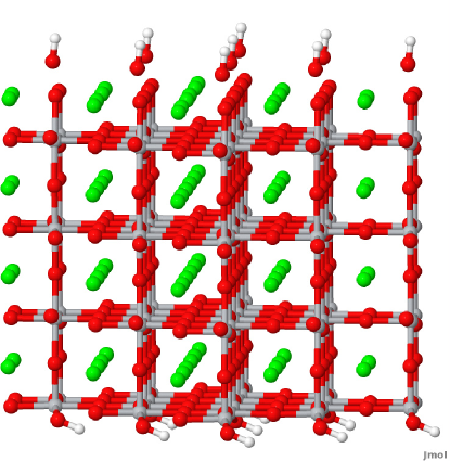
Adding external species to a surface won’t make it insulating, as the excess charge is half an electron per cell (a periodic array of external species can provide only integer multiples of ). Doubling the surface unit cell leads to exactly plus or minus one electron, that now allows for an insulating state. We compensate this excess charge with a split water molecule (H adsorbed on the “negative” AlO2 side, OH on the “positive” LaO side) per surface cell. We use a stoichiometric LaAlO3 slab with a thickness of four unit cells, a in-plane translational symmetry and we relax the structure without imposing any symmetry constraint. As usual, we use a vacuum dipole correction to ensure the correct cancellation of the macroscopic electric fields due to the asymmetry of the slab. At equilibrium, the structure appears as in Fig. 10. Note the tilted position of the H atoms on the AlO2 side, consistent with the geometry found in Ref. Son et al., 2010 for the H-LaAlO3/SrTiO3 system. The OH groups on the LaO side lie in a bridge site between two surface La atoms, thus occupying a natural lattice site for O. (An analogous location of the OH group was found on the SrO-terminated SrTiO3 surface decorated with dissociated water Guhl et al. (2010).) The system has a large insulating gap, almost equal to the bulk value, suggesting that this configuration might be fairly stable. We can estimate the energetics by considering a “wet cleavage” experiment where two LaAlO3 (001) surface are created and at the same time one free H2O molecule is split between the two terminations,
| (20) |
Here is the energy of the supercell described above with two LaAlO3 cells per surface unit and a thickness of four unit cells; is the bulk energy, calculated by including the antiferrodistortive tilt of the O octahedra, which now are allowed by symmetry; is the energy of a free water molecule, calculated by using a cubic box of approximately 10 Å lateral size. The resulting cleavage energy per surface area is 2.50 J/m2, which is the lowest value calculated in this work. This result suggests that adsorption of OH and H groups, which are ubiquitous in most experimental setups, is a very likely candidate to stabilize the LaAlO3 surface polarity. A study of LaAlO3(100) compensation via point defects was also recently reported in Ref. Seo and Demkov, 2011.
As a final remark, note that bound compensating charges, unlike the metallic carriers mediating electronic compensation, come in discrete units of . Therefore, in cases where bound-charge compensation occur, it is most appropriate to “count” the external charges per unit area, which must satisfy the relationship
| (21) |
Here (with integer) is the formal oxidation state of the external defect or adsorbate, and is the surface area per defect. Note that there exist defects (e.g. transition metal cations) that are stable in several oxidation states; of course, the actual that occurs in the situation of interest must be used in Eq. (21). In case of doubt, the Wannier-based analysis of Sec. II can be used to assess the formal oxidation state of a given defect.
IV Discussion
Here we shall put our results in the context of the current state-of-the-art in the field, especially regarding the fundamental theoretical understanding of the electrostatic stability of insulator surfaces.
IV.1 Insulating nature of the surface
As we mentioned several times when discussing our applications, it is likely that a non-polar (in the sense specified in this work) primitive surface will have a well-defined surface band gap. Here we shall further specify this point, to prevent dangerous generalizations.
It is certainly true that a polar surface with all the atoms in their bulk oxidation state cannot exist. If we insist on keeping the local stoichiometry fixed, some of the atoms must change their valence in order to avoid a diverging electrostatic energy. In many cases this produces partially filled electronic bands and a metallic surface. It is not difficult to imagine cases, however, where the surface atoms may change their oxidation state while preserving a gap in the spectrum. This would happen, for example, whenever the excess/defect charge amounts to an integer number of electrons, and there are ions in the lattice that have multiple stable oxidation states, e.g. most transition metals. Oxygen might also, in principle, change its formal valence from -2 to -1 to compensate a net surface charge – such a mechanism, stabilized via the formation of a peroxo bond, was reported in the case of a SrTiO3 surface by Bottin et al. Bottin et al. (2003). Therefore, a polar surface does not necessarily lead to a metallic surface. There are several other compensation mechanisms available (often accompanied by a reduction in the translational periodicity) that leave the surface insulating even without changes in the stoichiometry. We stress that in this latter case, however, the formal oxidation state of some atoms must change.
Also the statement that non-polar surfaces are insulating is far from universal. Indeed, by replicating a sufficiently pathological choice for the bulk primitive unit, one might end up with a surface that has a very awkward bonding configuration. This might produce a dramatic departure from the bulk bonding environment, and in such cases it is well possible that one or more surface bands may close the band gap. An example of how this may happen is provided by our A2-type SrTiO3 surface, where the band gap is reduced to a tiny value of about 0.1 eV. Gap closure would also occur for our LaAlO3 surface models for a large enough ; at some point the electrostatic energy of the large LaO- and AlO2-type terraces would become too large and eventually the gap would close. Note that surface relaxation usually helps stabilizing the truncated bonding network; in cases where our arguments would predict an insulating and non-polar surface, it is not infrequent to observe that a sizeable band gap opens only after full atomic relaxation.
In conclusion, the relationship between electrostatic stability and insulating nature is certainly not a rigorous one. It is nonetheless a useful guideline, in the sense that if the surface bonding environment is not too pathological and the solid has a marked ionic character one usually expects a non-polar surface to be insulating. Note that the insulating/metallic nature of a formally non-polar termination is more an issue of chemistry than of electrostatics – it boils down to the chemical driving force for the atoms to preserve their bulk-like oxidation state. If the surface becomes metallic this will happen through a local rearrangement of the electron cloud; the total surface charge won’t change.
IV.2 Covalency arguments and “weak polarity”
The (001) surfaces of II-IV perovskites such as SrTiO3, BaTiO3, etc. are classified as non-polar within our definitions, consistent with Tasker’s assumption of formal ionic valence. Goniakowski, Finocchi and Noguera Goniakowski et al. (2008) challenged Tasker’s classification by invoking covalent bonding effects, which would produce a smearing of the electron cloud. This, in turn, would produce a distribution of the charge between the oxide layers that differs from their formal ionic charges. According to this interpretation, SrTiO3(001) was classified as “weakly polar”.
The disagreement between the two interpretations is rooted in the way the electronic charge density is partitioned into individual building blocks at the bulk level. Choosing Mulliken or Bader populations inevitably leads to a fractional charge per ion that is typically smaller than the (integer) formal oxidation state, and the individual SrO and TiO2 layers appear charged. While these ideas have certainly some merit, there are severe drawbacks as well. The most important one is that, by insisting on a partition of the electron cloud based exclusively on the total charge density , one thwarts any further attempt at linking the discussion of surface electrostatics to the theory of polarization in bulk solids. Powerful and rigorous results of the modern theory of polarization, e.g. the “interface theorem”, are inconsistent with a description of surface polarity in terms of Mulliken, Bader or even Born effective charges. (The fact that in II-IV perovskites the individual AO and BO2 layer do not satisfy the acoustic sume rule separately is sometimes taken as a further argument in support of the weak polarity concept.) The theory of bulk polarization implies a wavefunction-based partition of . The natural tool in that sense are the spatially localized Wannier function as we discussed in section II. Covalency effects are irrelevant in this context, except that they are implicitly accounted for through the location of the ground-state Wannier centers and their spatial spread. Using Wannier functions might appear unnatural and complicated at first sight, but eventually they really lead to drastic simplifications and to an intuitive physical picture. In particular, if one wants to recover the intuitive classical formula , there is simply no other way around.
We believe that full consistency between the theory of bulk polarization and the theory of surface polarity is a must. Therefore, we caution against the use of concepts such as weak polarity or covalent charges as they are are inconsistent with the former.
IV.3 Other oxide surfaces
IV.3.1 Ferroelectric perovskites
As the concept of surface polarity is intimately linked to the polarization of the bulk solid, , it is particularly insightful to discuss cases where has a non-trivial behavior, as in ferroelectric perovskite materials. Consider a (100)-oriented slab of BaTiO3, with the spontaneous polarization vector, oriented along the normal to the surface. Imagine that we have a stoichiometric slab with ideal BaO and TiO2 terminations, and a monodomain state with perfect periodicity; assume also that points towards the TiO2-type surface.
Both surfaces are polar, as . Contrary to the LaAlO3 example, however, here is not a simple fraction (plus or minus one half) of the polarization quantum . Here , where is a real number of the order of 0.25-0.35 (depending on the in-plane strain imposed to the film). Therefore, it might be technically difficult in a calculation to construct a commensurate supercell where is accurately compensated by an appropriate coverage of charged adsorbates or defects (unless happens by accident to be exactly equal to a rational number with a small denominator). A possible trick to circumvent this difficulty is using the so-called “virtual crystal approximation” (VCA) Stengel et al. (2011). Here a fractionally charged pseudopotential is introduced at the surface to reproduce the effect of a disordered array of defects with the appropriate coverage. This way, the surface can be made insulating and charge-neutral at a low computational cost; the price to pay is that the VCA does not lend itself easily to the calculation of surface-specific properties, e.g. the energetics of a given compensation mechanism.
A second important example is that of I-V ferroelectric perovskites, e.g. KNbO3. Here the ferroelectric contribution to the polarization, , adds up to the “compositional” built-in cell dipole, Stengel (2011) which is (as in LaAlO3, the layers are formally charged, although here AO layers are negative and BO2 are positive). Note that, if were (again, by accident) equal to half a quantum of polarization, both NbO2- and KO-terminated (100) surfaces would be non-polar (i.e. would cancel out ), provided that the spontaneous polarization points in the correct direction. This would be away from the surface for the -type NbO2 termination, and towards the surface for the KO termination.
Finally, it is worthwile mentioning the case of BiFeO3. This material appears complicated at first sight, because of the tilted polarization axis [ is oriented along the (111) direction] and the compositional layer charges of (both Fe and Bi are formally 3+ ions). However, within the formalism established in this work, predicting the excess surface charge density that will be present at a given ideal termination becomes trivially simple. For example, at the FeO2 (100) termination we have [just like in the case of the AlO2-terminated LaAlO3(100) surface] an excess built-in charge of C/m2. To this value we need to add the projection of along the (100) axis, which amounts to approximately the same value. Neaton et al. (2005) Therefore, if points towards the FeO2-type (100) termination, this surface will be in practice only very weakly charged or even neutral. It goes without saying that the composition of the surface “pins” the out-of-plane component of the polarization to a fixed value that cannot be switched (unless the surface composition itself is changed, see Ref. Wang et al., 2009).
IV.3.2 ZnO
The use of ZnO in many technological areas, as well as the recent progress in fabricating tailored nanostructures and functional surfaces with this material, have generated a widespread interest in the fundamental properties of its polar (0001) surface. Wander et al. (2001); Valtiner et al. (2009); Lauritsen et al. (2011). Several possible compensation mechanisms involving, e.g. metallic free carriers Wander et al. (2001), hydroxylation/protonation Valtiner et al. (2009) or stoichiometry changes Lauritsen et al. (2011) have been proposed over the years. In spite of this activity, the question of exactly how much excess charge is present at the polar Zn- or O- terminated surfaces is still a source of confusion.
For instance, there is a common belief that, starting from an ideal unreconstructed termination, removal of 1/4 of the surface ions will lead to perfect compensation of the polarity. Lauritsen et al. (2011) This would be true if ZnO crystallized in zincblende phase. However, bulk ZnO is wurtzite-type, which means that on top of the compositional (zincblende-like) dipole it has also a non-trivial spontaneous . Dal Corso et al. (1994) This is of course not switchable, unlike the ferroelectric materials discussed in the previous section, but it does need to be taken into account when computing the surface charge. First-principles calculations of have reported relatively small values (compared to a hypothetical zincblende reference structure) of in bulk ZnO, of the order of 0.02-0.07 C/m2 Gopal and Spaldin (2006); Dal Corso et al. (1994). This implies that the necessary correction to the zincblende-like excess charge of per surface cell is of the order of 0.01-0.03 electrons. Even if this correction is not large, one should keep in mind that, in a hypothetical free-slab calculation of ZnO where 1/4 of the O (and Zn) surface ions have been removed, after full relaxation there will be a non-zero residual macroscopic electric field in the slab of approximately . Here is the vacuum permittivity and is the static dielectric constant of ZnO (including piezoelectric effects). In fact, this observation was used to calculate the spontaneous polarization of wurtzite BeO several years before the modern theory of polarization was developed. Posternak et al. (1990)
IV.4 Semiconductor surfaces
While our arguments apply most naturally to ionic materials, where the assignment of the localized Wannier charges to a given atom is unambiguous, with some care they can be easily adapted to covalently bonded insulators. The main difficulty is that in semiconductors (e.g. Si) the maximally-localized Wannier functions tend to occupy bond-centered sites, and are shared between two atoms – assigning a given Wannier function to either atom that participate to the bond is then entirely arbitrary. Nevertheless, one can usually establish a reasonable convention for partitioning the bulk solid into well-defined units. For instance, in Si one could assign four spin-up Wannier functions (their centers would form a tetrahedron around the nucleus) to one atom and four spin-down Wannier functions to the other atom in the basis. (It might appear somewhat artificial to use such a spin-split basis; however, for the present discussion, the information about the spin is irrelevant, only the charge density of the Wannier functions really matters.) Then, this decomposition yields a basis of two WIs that individually retain the full symmetry of the lattice, are charge-neutral and have zero dipole moment. Primitive Si surfaces are then predicted to be non-polar, but chemically they will be highly reactive because of the singly occupied “dangling bonds”; this picture is consistent with the widely accepted understanding of Si surfaces. It is easy to see that by saturating these bonds with H one always obtains a non-polar and chemically stable surface (H does not add a net charge density as it contributes one electron and one proton to each dangling orbital). Alternatively, one could supply one Sr atom every two dangling bonds; this stabilization mechanism is important for growth of perovskite oxide films on Si substrates. Först et al. (2004); Kolpak et al. (2010) Interestingly, in the case of the Sr-decorated surface, further oxidation does not change the surface charge count, Först et al. (2004) as additional O atoms achieve a closed-shell configuration by incorporating the electron pairs already present in the saturated dangling bonds. This is a system where oxygen adsorption does not change the surface charge, in striking contrast with typical ferroelectric surfaces. Wang et al. (2009)
Of course, one could prefer to use other conventions, e.g. assign two doubly occupied Wannier functions to each Si atom. This way the Si(100) or (111) surfaces would be understood as “polar”, and they are indeed polar if one insists on counting electrons two-by-two (the dangling bonds would need to be either empty or saturated, without the necessary countercharge to balance the electrostatics). This means that the concept of polar surface becomes somewhat ill-defined if the solid has no ionic character whatsoever. Note that the formalism developed in Ref. Vanderbilt and King-Smith, 1993, on which the present work heavily relies, provides always a rigorous means of calculating the surface charge from bulk properties, regardless of the (ionic or non-ionic) nature of the insulator, and independently of the convention that one uses to “assign” the bound electron charges to a given lattice site. A more extensive treatment of the covalent case can be found in Ref. Vanderbilt and King-Smith, 1993, and was recently discussed also in Ref. Bristowe et al., 2011.
IV.5 Interfaces
In this work we decided to focus on surfaces, which is a special case of interface between two materials (one of them is vacuum). Whenever the second material is another crystalline insulator, the same arguments apply, but the “electrostatic phase diagram” can be substantially richer. The simplest case is that of two materials that have the same crystal structure, and we assume coherent epitaxy, i.e. both semi-infinite regions have the same in-plane periodicity and the same crystallographic orientation of the atomic planes. However, there might be more complex cases – for example, the participating materials have different bulk structures, or they are not oriented along the same crystallographic direction. In any case, the electrostatics is always governed by the intuitive classical formula,
| (22) |
Here is the polarization in either material, calculated by choosing a certain basis for the primitive basis of atoms and Wannier functions; is the “remainder” interface charge, that is left behind once one removes all the bulk-like primitive units on either side; is the normal to the surface plane. As in the case of surfaces, we define an interface non-polar if, for an ideal termination of both materials with the maximum allowed translational symmetry one has .
V Conclusions
In summary, we have revisited the concept of polar surface within the context of the modern theory of bulk polarization. Our definition, which is consistent with the bound (and discrete) nature of electrons in the insulating state of matter, puts Tasker’s classification on a firmer theoretical grounds, and corroborates it at the microscopic level. We further complete Tasker’s formalism with an additional term, which comes from the polarization of the electron cloud in solids that spontaneously break space inversion symmetry. Our calculations of non-polar LaAlO and SrTiO3(111) surfaces, and of compensation mechanisms at LaAlO, demonstrate that our formalism provides a convenient way of describing the net surface charge in terms of bulk polarization and external sources (either “bound” or “free”). We have also illustrated some practical analysis tools that can be used to monitor the equilibrium distribution of compensating charge in a calculation. We hope that these techniques will be helpful for future first-principles studies, and more generally as a conceptual basis to rationalize the many interesting phenomena occurring at the surfaces of insulating materials.
Acknowledgments
I am indebted to D. Vanderbilt for a critical read of the manuscript and many illuminating discussions. This work was supported by DGI-Spain through Grants No. MAT2010-18113 and No. CSD2007-00041, and by the European Union through the project EC-FP7, Grant No. NMP3-SL-2009-228989 “OxIDes”. I thankfully acknowledge the computer resources, technical expertise and assistance provided by the Red Española de Supercomputación (RES) and by the Supercomputing Center of Galicia (CESGA).
References
- Goniakowski et al. (2008) J. Goniakowski, F. Finocchi, and C. Noguera, Reports on Progress in Physics 71, 016501 (2008).
- Enterkin et al. (2010) J. A. Enterkin, A. K. Subramanian, B. C. Russell, M. R. Castell, K. R. Poeppelmeier, and L. D. Marks, Nature Materials 9, 245–248 (2010).
- Lauritsen et al. (2011) J. V. Lauritsen, S. Porsgaard, M. K. Rasmussen, M. C. R. Jensen, K. Bechstein, Ralf an d Meinander, B. S. Clausen, S. Helveg, R. Wahl, G. Kresse, and F. Besenbacher, ACS Nano 5, 5987 (2011).
- Levchenko and Rappe (2008) S. V. Levchenko and A. M. Rappe, Phys. Rev. Lett. 100, 256101 (2008).
- Yun and Altman (2007) Y. Yun and E. I. Altman, Journal of the American Chemical Society 129, 15684 (2007).
- Garrity et al. (2010) K. Garrity, A. M. Kolpak, S. Ismail-Beigi, and E. I. Altman, Advanced Materials 22, 2969 (2010), ISSN 1521-4095.
- Son et al. (2010) W.-J. Son, E. Cho, J. Lee, and S. Han, Journal of Physics: Condensed Matter 22, 315501 (2010).
- Cen et al. (2008) C. Cen, S. Thiel, G. Hammerl, C. W. Schneider, K. E. Andersen, C. S. Hellberg, J. Mannhart, and J. Levy, Nature Materials 7, 298 (2008).
- Xie et al. (2010) Y. Xie, C. Bell, T. Yajima, Y. Hikita, and H. Y. Hwang, Nano Letters 10, 2588 (2010).
- García et al. (2009) V. García, S. Fusil, K. Bouzehouane, S. Enouz-Vedrenne, N. Mathur, A. Barthélémy, and M. Bibes, Nature (London) 460, 81 (2009).
- Vanderbilt and King-Smith (1993) D. Vanderbilt and R. D. King-Smith, Phys. Rev. B 48, 4442 (1993).
- Tasker (1979) P. W. Tasker, Journal of Physics C: Solid State Physics 12, 4977 (1979).
- King-Smith and Vanderbilt (1993) R. D. King-Smith and D. Vanderbilt, Phys. Rev. B 47, R1651 (1993).
- Stengel and Vanderbilt (2009) M. Stengel and D. Vanderbilt, Phys. Rev B 80, 241103 (2009).
- Marzari and Vanderbilt (1997) N. Marzari and D. Vanderbilt, Phys. Rev. B 56, 12847 (1997).
- Stengel and Spaldin (2006) M. Stengel and N. A. Spaldin, Phys. Rev. B 73, 075121 (2006).
- Wu et al. (2006) X. Wu, O. Diéguez, K. M. Rabe, and D. Vanderbilt, Phys. Rev. Lett. 97, 107602 (2006).
- Wu et al. (2008) X. Wu, M. Stengel, K. M. Rabe, and D. Vanderbilt, Phys. Rev. Lett. 101, 087601 (2008).
- Resta and Vanderbilt (2007) R. Resta and D. Vanderbilt, in Physics of Ferroelectrics: A Modern Perspective, edited by K. M. Rabe, C. H. Ahn, and J.-M. Triscone (Springer-Verlag, Berlin Heidelberg, 2007).
- Brouder et al. (2007) C. Brouder, G. Panati, M. Calandra, C. Mourougane, and N. Marzari, Phys. Rev. Lett. 98, 046402 (2007).
- Ohtomo and Hwang (2004) A. Ohtomo and H. Y. Hwang, Nature 427, 423 (2004).
- Bristowe et al. (2011) N. C. Bristowe, P. B. Littlewood, and E. Artacho, Journal of Physics: Condensed Matter 23, 081001 (2011).
- Higuchi and Hwang (2008) T. Higuchi and H. Y. Hwang, arXiv:1105.5779 (2008).
- Eglitis and Vanderbilt (2008) R. I. Eglitis and D. Vanderbilt, Phys. Rev. B 77, 195408 (2008).
- Bachelet et al. (2009) R. Bachelet, F. Sánchez, J. Santiso, C. Munuera, C. Ocal, and J. Fontcuberta, Chemistry of Materials 21, 2494 (2009).
- Marks et al. (2009) L. D. Marks, A. N. Chiaramonti, F. Tran, and P. Blaha, Surf. Sci. 603, 2179–2187 (2009).
- Stengel et al. (2011) M. Stengel, P. Aguado-Puente, N. A. Spaldin, and J. Junquera, Phys. Rev. B 83, 235112 (2011).
- Stengel (2011) M. Stengel, Phys. Rev. Lett. 106, 136803 (2011).
- Kolpak et al. (2010) A. M. Kolpak, F. J. Walker, J. W. Reiner, Y. Segal, D. Su, M. S. Sawicki, C. C. Broadbridge, Z. Zhang, Y. Zhu, C. H. Ahn, et al., Phys. Rev. Lett. 105, 217601 (2010).
- Först et al. (2004) C. J. Först, C. R. Ashman, K. Schwarz, and P. E. Blöchl, Nature 427, 53 (2004).
- Bi et al. (2010) F. Bi, D. F. Bogorin, C. Cen, C. W. Bark, J.-W. Park, C.-B. Eom, and J. Levy, Appl. Phys. Lett. 97, 173110 (2010).
- Guhl et al. (2010) H. Guhl, W. Miller, and K. Reuter, Phys. Rev. B 81, 155455 (2010).
- Seo and Demkov (2011) H. Seo and A. A. Demkov, Phys. Rev. B 84, 045440 (2011).
- Bottin et al. (2003) F. Bottin, F. Finocchi, and C. Noguera, Phys. Rev. B 68, 035418 (2003).
- Neaton et al. (2005) J. B. Neaton, C. Ederer, U. V. Waghmare, N. A. Spaldin, and K. M. Rabe, Phys. Rev. B 71, 014113 (2005).
- Wang et al. (2009) R. V. Wang, D. D. Fong, F. Jiang, M. J. Highland, P. H. Fuoss, C. Thompson, A. M. Kolpak, J. A. Eastman, S. K. Streiffer, A. M. Rappe, et al., Phys. Rev. Lett. 102, 047601 (2009).
- Wander et al. (2001) A. Wander, F. Schedin, P. Steadman, A. Norris, R. McGrath, T. S. Turner, G. Thornton, and N. M. Harrison, Phys. Rev. Lett. 86, 3811 (2001).
- Valtiner et al. (2009) M. Valtiner, M. Todorova, G. Grundmeier, and J. Neugebauer, Phys. Rev. Lett. 103, 065502 (2009).
- Dal Corso et al. (1994) A. Dal Corso, M. Posternak, R. Resta, and A. Baldereschi, Phys. Rev. B 50, 10715 (1994).
- Gopal and Spaldin (2006) P. Gopal and N. Spaldin, Journal of Electronic Materials 35, 538 (2006).
- Posternak et al. (1990) M. Posternak, A. Baldereschi, A. Catellani, and R. Resta, Phys. Rev. Lett. 64, 1777 (1990).