Magnetic-Field-Induced Stabilization of Non-Equilibrium Superconductivity
Abstract
A small magnetic field is found to enhance relaxation processes in a superconductor thus stabilizing superconductivity in non-equilibrium conditions. In a normal-metal (N) – insulator – superconductor (S) tunnel junction, applying a field of the order of leads to significantly improved cooling of the N island by quasiparticle (QP) tunneling. These findings are attributed to faster QP relaxation within the S electrodes as a result of enhanced QP drain through regions with locally suppressed energy gap due to magnetic vortices in the S leads at some distance from the junction.
pacs:
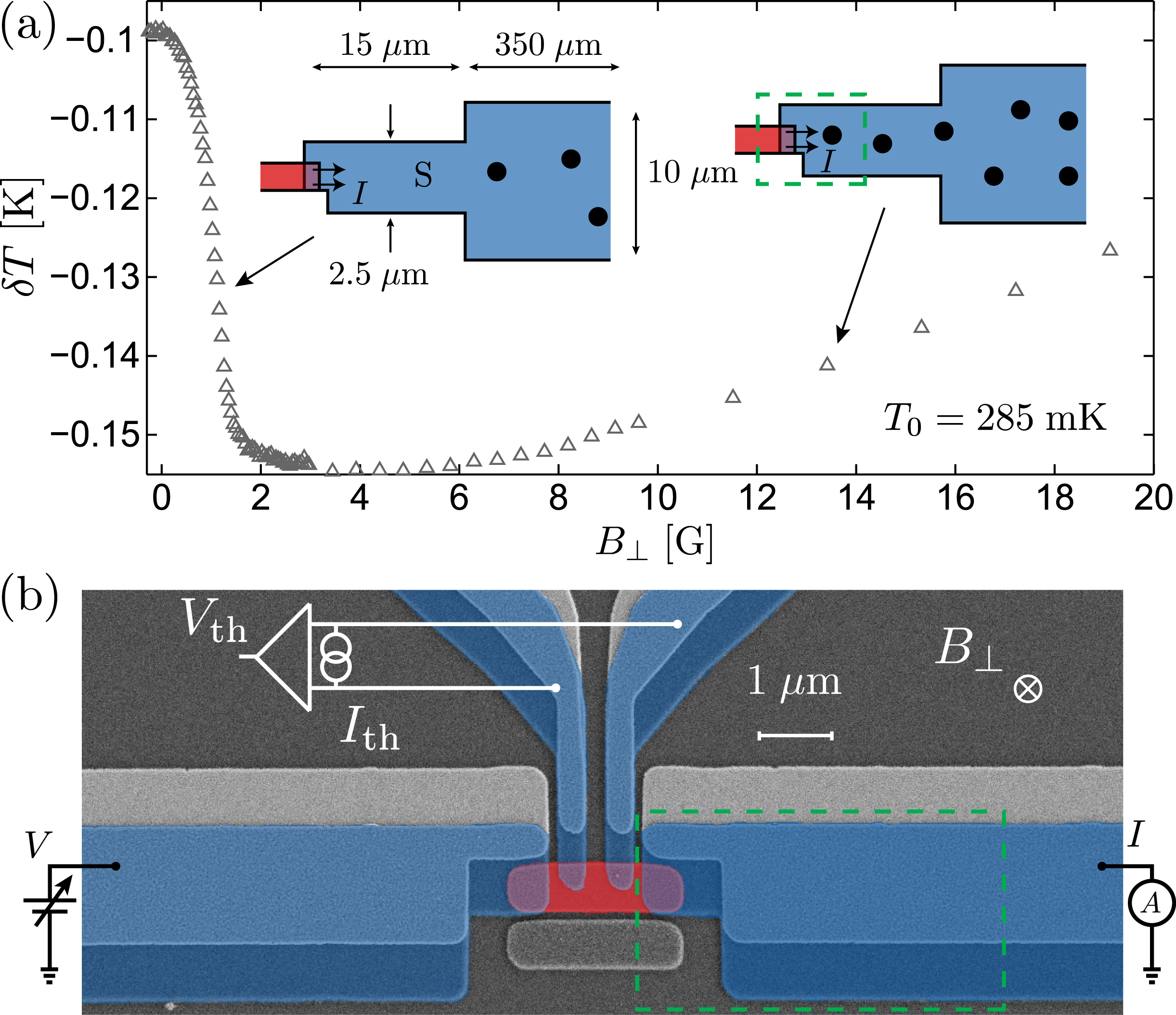
74.50.+r, 74.25.Ha, 73.40.RwIn this Letter, we report an observation that appears counterintuitive at first: a small magnetic field is found to stabilize superconductivity under quasiparticle (QP) injection. In our experiment, the cooling power of normal-metal (N) – insulator (I) – superconductor (S) tunnel structures is enhanced in perpendicular magnetic fields . Measured maximum temperature drop relative to a starting bath temperature exhibiting this behavior is shown in Fig. 1 . The improvement is unexpected, as in general the effect of a magnetic field is to suppress superconductivity. Electronic cooling in NIS junctions in the presence of magnetic fields in both perpendicular and parallel orientations has been studied before arutyunov00 , but only in higher fields where the cooling power was already reduced due to diminishing superconducting energy gap . On the other hand, the creation of magnetic vortices abrikosov57 has been shown to enhance QP relaxation in superconducting aluminum, as the QPs become trapped and thermalize in the regions of reduced ullom98b . Here we demonstrate that the additional relaxation channel due to enhanced QP drain through regions occupied by magnetic vortices enhances the superconducting performance of S leads and improves the electronic cooling in NIS junctions. This can be of relevance in superconducting qubits martinis09 ; catelani11 ; lenander11 ; gunnarsson04 , resonators devisser11 and in hybrid SINIS turnstiles pekola08 in reducing the effects from nonequilibrium and residual QPs arising due to drive and microwave radiation from the environment. Moreover, improved relaxation caused by vortex creation in the S leads can partially explain the “re-entrant superconductivity” observed in Zn and Al nanowires chen09 ; chen11 . In the present case, as sketched in Fig. 1 , vortex formation in the S electrodes away from the NIS junction improves relaxation of the injected QPs and leads to enhanced cooling of the N island. In higher fields, vortices move closer to the junction, deteriorating the cooling power.
In an NIS junction, acts as an energy filter for the tunneling QP nahum93 ; nahum94 ; giazotto06 ; leivo96 . At low temperatures and for bias voltages across the junction, the electrons in the N electrode cool considerably below the phonon temperature by hot QP extraction. The effect can be made more pronounced in a symmetric double junction SINIS structure with a small N island contacted to S leads via two NIS junctions leivo96 , allowing to construct practical solid-state refrigerators for cooling thin-film detectors to temperatures close to clark04 ; clark05 . The performance of actual devices depends crucially on the relaxation of the QPs that are injected into the S electrode, as the superconductor overheating diminishes the cooling power at an NIS junction because of enhanced QP backtunneling. The excess QP density close to the junction can be diminished by fabricating the S electrodes very thick clark04 , or covering them partially by a layer of normal metal that acts as a QP trap joyez94 ; pekola00 ; court08 . The QP population is typically modeled in terms of a diffusion equation, describing their recombination retarded by phonon retrapping, and other loss mechanisms rothwarf67 ; kaplan76 ; ullom98a ; ullom00a ; rajauria09 . Converting the excess density into an effective, position-dependent temperature ullom00b ; arutyunov11 , one finds that at phonon temperatures the S leads can be overheated on a length scale ranging from tens of micrometers to a millimeter, as the electron-phonon relaxation and electronic heat conduction are exponentially suppressed compared to their normal state values kaplan76 ; bardeen59 .
Here we present data from one of several measured symmetric SINIS structures similar to that shown in Fig. 1 , fabricated at different times and electrically characterized in a dilution refrigerator down to bath temperature. The same qualitative behavior was observed in all structures with the same geometry. A copper island of area is contacted by four overlap-type Al/Al-oxide/Cu NIS junctions. The Al electrodes with zero-temperature energy gap become superconducting below . Compared to the two small (probe) junctions in the middle, the two outer (cooler) junctions at the ends of the island have larger overlap area and therefore lower normal state tunnel resistance each. The structures were fabricated on an oxidized silicon substrate by standard electron beam lithography and two-angle shadow evaporation of Al and Cu through a polymer resist mask. First, an Al layer of thickness was deposited, followed by in situ oxidation in the e-beam evaporator chamber in a few millibars of pure oxygen for a few minutes. Finally, a Cu layer of thickness was evaporated at a different angle, forming the N island with four tunnel contacts to the Al electrodes. In addition, Cu replicas of the Al leads form large area tunnel junctions by partly covering the Al layer, serving as QP traps, albeit of suboptimal performance pekola00 .
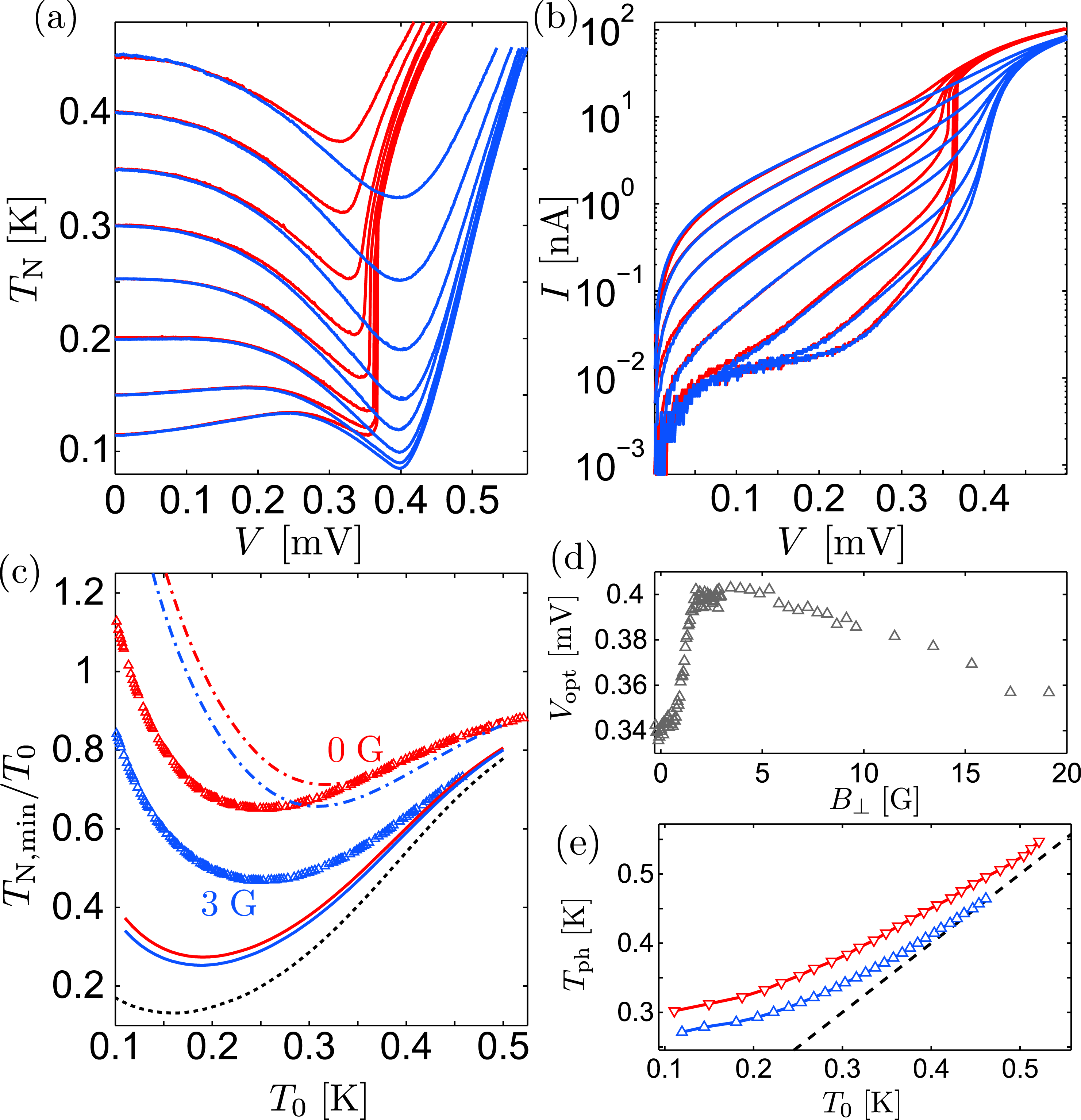
The island electron temperature is measured by biasing the probe junctions by a constant current , and measuring the voltage drop , calibrated against at . The solid lines in Fig. 2 show the measured as a function of at bath temperatures between 0.1 and , in zero field (red) and at (blue). In the following, the minimum along each curve at a fixed is denoted by , and the corresponding bias voltage by . The strong influence of small on the cooling is evident: At the maximum cooling at each increases by several tens of percents. The cooler QP current displays analogous behavior, Fig. 2 . At the same time the optimum bias voltage increases, Fig. 2 , while heating at diminishes. The cooling enhancement is symmetric in the applied field.
The improved refrigeration is summarized in Fig. 2 , where the symbols show the -dependent relative minimum temperature in zero field and close to optimum . We observed the improved cooling also with Ag as the normal metal, in single NIS junctions with various gradually widening lead geometries close to the junction, and in a parallel field. In the latter case, the required fields were larger by an order of magnitude and dependent on the field orientation in the sample plane.
The thin-film Al leads behave as a type II superconductor, so that penetrates in the form of vortices tinkhambook ; tinkhamharper . Based on a typical normal state resistivity of our Al at timofeevpeltonen , the elastic mean free path is . With the Bardeen-Cooper-Schrieffer (BCS) coherence length and the London penetration depth for bulk pure Al at low-temperatures, one obtains and for our Al films with the Ginzburg-Landau parameter and the lower critical field for the bulk material . As sketched in Fig. 1 , the S leads of the cooler junctions have an initial width of approximately . At a distance of away from the island, they widen to width and continue for before again widening to width and connecting to large-area bonding pads further away. The magnetic field below which vortices are completely expelled from a long and narrow S lead of width is of the order of stan04 , where is the magnetic flux quantum. For a strip of width , , whereas results in . Taking into account the demagnetizing factor of our films we can conclude that the initial increase in in Fig. 1 observed below and the turn-back that starts close to are consistent with vortex penetration into the wide and narrow parts of the lead, respectively.
In Ref. ullom98b, with large area NIS junctions, the increased sub-gap conductance at small could be directly associated with the fraction of vortices in the junction area. In contrast, we do not observe an increase in the cooler junction sub-gap current in the small fields. The thermometer junctions with narrower S electrodes are not considerably affected in fields even at bias voltages close to , indicating that vortices exist only further away from these junctions.
We assume quasiequilibrium with a local electronic temperature different from the bath temperature giazotto06 . The cooling power depends on the temperatures and of N and S electrodes near the interface. They are found from the equation of heat balance in the N island
| (1) |
and of the heat conduction in each superconducting lead,
| (2) |
with the boundary conditions , and at for the right or left lead ( is a wire cross section). The temperature of the lead at the interface is . The first term in the rhs of Eq. (1) describes the heat transferred to phonons in the normal island. The island volume and electron-phonon coupling constant are and , respectively. in Eq. (1) is a constant residual power due to imperfect RF-filtering of the measurement. The heat extracted from the island through a single NIS junction and the heat injected into an S lead by tunneling are
| (3) |
Here, , , are the Fermi occupation factors, and is the normalized BCS density of states (DOS).
The rhs of Eq. (2) is the power transferred from the unit volume of the superconductor into the (unbiased) normal trap with temperature . Similarly to Eq. (3),
where is the time of relaxation to the trap, being the trap/superconductor tunnel resistance of unit contact area and denotes the normal state DOS at the Fermi energy per one spin projection, while is internal energy of the superconductor with the gap at temperature Kopnin2001 . In Eq. (2) we assume that the electronic subsystem releases heat to the normal trap rather than directly to the phonon bath. Indeed, the trap relaxation rates are s-1 for the contact resistances k while the electron-phonon relaxation rate in aluminium is for the experimental temperatures. Equation (2) is obtained by averaging it over inhomogeneities in , assumed to have low areal density and short scale compared to the inelastic relaxation length, i.e., the scale of variations. The thermal conductivity and the heat current into the trap are spatially averaged quantities and for a superconductor having a normal fraction proportional to which models the presence of vortices. The thermal conductivity bardeen59 , , and the heat current, , of a superconductor at are exponentially suppressed relative to their normal-state values and according to and . Here , and is the Al normal state electrical conductivity.
Because of exponentially small and at , the temperature can be very sensitive to the vortex fraction . For reference, the black dotted line in Fig. 2 shows the calculated as a function of in the limit of perfect thermalization, . The red and blue solid lines are the results of Eqs. (1) and (2) for equilibrium phonons in the island, . The red line is obtained with , so that the S electrode overheats at most all the way to the large-area bonding pad. Especially towards the lowest bath temperatures, the observed cooling in zero field is considerably weaker than the prediction of the model for perfect thermalization of S electrodes. To estimate the effect in the optimum field, we set in the wide electrode section, but keep in the narrower section. The result is shown as the solid blue line in Fig. 2 . In our samples, a considerable fraction of the N island is located on top of the S electrodes such that can be essentially higher than . As a worst-case estimate, we assume the N island phonons to be overheated to . The result for the above two cases of full and partial S electrode overheating are shown as the red and blue dash-dotted lines, respectively. The predicted influence of the field is now stronger, and the measured cooling in both zero and optimum field is bracketed between the solid and the dash-dotted line. Approximate phonon temperatures at that reproduce exactly the observed are displayed in Fig. 2 . In both zero field (red, upper curve) and in the optimum field (lower curve), reflects the temperature of the QPs close to the junction, ranging from close to at to around at . We stress that the large field-induced improvement evident in Figs. 1 and 2 is observed because of the considerable S electrode overheating in zero field. It causes also the significant increase in as is increased from zero: is close to the ideal value giazotto06 only at optimum .
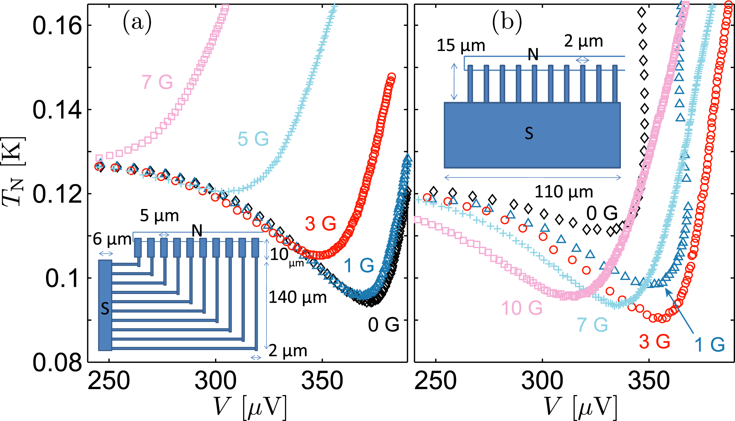
To emphasize the role of the S electrode geometry, we performed additional experiments on parallel SINIS coolers. As shown in Fig. 3 , in a sample with initially wide leads, vortices form first close to the junctions, and applying monotonously weakens the cooling. In contrast, with narrow leads close to the junctions as in Fig. 3 , the cooling is optimized at a finite .
In conclusion, we observed that a small magnetic field enhances relaxation processes in a superconductor thus stabilizing superconductivity in non-equilibrium conditions. Significantly improved electronic cooling in a tunnel junction was achieved in a small perpendicular magnetic field. The enhancement of relaxation can be relevant also for “re-entrant superconductivity” observed in Zn nanowires chen09 ; chen11 driven out of equilibrium by supercritical current. A quasiequilibrium model accounts for the field-improved QP relaxation in the S leads. The work can provide means for optimizing the performance of superconducting nanostructures, and sheds additional light on the unsolved problem of nonequilibrium and residual quasiparticles.
Acknowledgements.
We thank H. Courtois, F. Giazotto, F. Hekking and F. Taddei for useful discussions and T. Aref for assistance in sample fabrication. We acknowledge financial support from the European Community’s FP7 Programme under Grant Agreement No. 228464 (MICROKELVIN, Capacities Specific Programme), the Academy of Finland (project number 139172), the Finnish Academy of Science and Letters and EPSRC through grant EP/F040784/1. NBK acknowledges support by the Program “Quantum Physics of Condensed Matter” of the Russian Academy of Sciences.References
- (1) K. Yu. Arutyunov et al., J. Appl. Phys. 88, 326 (2000).
- (2) A. A. Abrikosov, Sov. Phys. JETP 5, 1174 (1957).
- (3) J. N. Ullom et al., Appl. Phys. Lett. 73, 2494 (1998).
- (4) J. M. Martinis et al., Phys. Rev. Lett. 103, 097002 (2009).
- (5) G. Catelani et al., Phys. Rev. Lett. 106, 077002 (2011).
- (6) M. Lenander et al., arXiv:1101.0862.
- (7) D. Gunnarsson et al., Phys. Rev. B 70, 224523 (2004).
- (8) P. J. de Visser et al., Phys. Rev. Lett. 106, 167004 (2011).
- (9) J. P. Pekola et al., Nature Physics 4, 120 (2008).
- (10) Yu Chen et al., Phys. Rev. Lett. 103, 127002 (2009).
- (11) Yu Chen et al., Phys. Rev. B 83, 054505 (2011).
- (12) M. Nahum and J. M. Martinis, Appl. Phys. Lett. 63, 3075 (1993).
- (13) M. Nahum et al., Appl. Phys. Lett. 65, 3123 (1994).
- (14) F. Giazotto et al., Rev. Mod. Phys. 78, 217 (2006).
- (15) M. M. Leivo et al., Appl. Phys. Lett. 68, 1996 (1996).
- (16) A. M. Clark et al., Appl. Phys. Lett. 84, 625 (2004).
- (17) A. M. Clark et al., Appl. Phys. Lett. 86, 173508 (2005).
- (18) P. Joyez et al., Phys. Rev. Lett. 72, 2458 (1994).
- (19) J. P. Pekola et al., Appl. Phys. Lett. 76, 2782 (2000).
- (20) N. A. Court et al., Phys. Rev. B 77, 100501 (2008).
- (21) A. Rothwarf and B. N. Taylor, Phys. Rev. Lett. 19, 27 (1967).
- (22) S. B. Kaplan et al., Phys. Rev. B 14, 4854 (1976)
- (23) J. N. Ullom et al., Phys. Rev. B 58, 8225 (1998).
- (24) J. N. Ullom et al., Phys. Rev. B 61, 14839 (2000).
- (25) S. Rajauria et al., Phys. Rev. B 80, 214521 (2009).
- (26) J. N. Ullom and P. A. Fisher, Physica B 284-288, 2036 (2000).
- (27) K. Yu. Arutyunov et al., Phys. Rev. B 83, 104509 (2011).
- (28) J. Bardeen et al., Phys. Rev. 113, 982 (1959).
- (29) M. Tinkham, Introduction to Superconductivity, 2nd ed. (McGraw-Hill, 1996).
- (30) M. Tinkham, Phys. Rev. 129, 2413 (1963), F. E. Harper and M. Tinkham, ibid. 172, 441 (1968).
- (31) A. V. Timofeev et al., Phys. Rev. Lett. 102, 200801 (2009), J. T. Peltonen et al., ibid. 105, 097004 (2010).
- (32) G. Stan et al., Phys. Rev. Lett. 92, 097003 (2004).
- (33) N.B. Kopnin, Theory of Nonequilibrium Superconductivity (Oxford, 2001).