Heat conduction in graphene flakes with inhomogeneous mass interface
Abstract
Using nonequilibrium molecular dynamics simulations, we study the heat conduction in graphene flakes composed by two regions. One region is mass-loaded and the other one is intact. It is found that the mass interface between the two regions greatly decreases the thermal conductivity, but it would not bring thermal rectification effect. The dependence of thermal conductivity upon the heat flux and the mass difference ratio are studied to confirm the generality of the result. The interfacial scattering of solitons is studied to explain the absence of rectification effect.
pacs:
65.80.Ck, 44.10.+i, 05.45.YvThermal rectification is a phenomenon that the heat flux runs preferentially along one direction and inferiorly along the opposite direction01.Casati.Nature (1, 2, 3, 4, 5, 6, 7, 8, 9, 10, 11, 12, 13, 14). It has attracted a great deal of attention in the last decade since it reveals the possibility to control the heat transportation process. With an improved understanding of thermal rectification, various devices like thermal transistors, thermal logic circuits and thermal diodes could be fabricated. Two methods are commonly used to design thermal rectifiers. The first method is to couple two or more anharmonic chains with different nonlinear potentials together03.Casati 2002 (3, 4, 5). The explanation for the observed rectification effect is that the phonon bands of different regions of the chain will change from overlap to separation when the heat flux is reversed. The asymmetry of interaction potential controls the phonon band shift and it plays the central role here. The second method is to implement asymmetric geometric shape in quasi-1D and 2D systems. For example, it is applied in deformed carbon nanotubes06.deformed CNT (6), carbon nanohorns07.horns (7), triangle shaped, trapezoid shaped and U-shaped graphene flakes08.Hu nanoletter (8, 9, 10). Thermal conductivity is higher when the heat flux runs from the narrow to the wide region. The explanation for the observed rectification is that the asymmetric geometric shape introduces asymmetric boundary scattering of phonons. The asymmetry of geometric shape controls the phonon scattering and it plays the central role in this case.
Recently a new procedure is considered by Chang et al. in carbon and boron nitride nanotubes11.science (11). They introduce the asymmetry of mass distribution by covering external platinum compound on the nanotubes. Comparing with nanotubes, the thermal contribution of the platinum compound can be neglected. So the mass-loading procedure is idealized by Chang et al. as changing the atomic mass of the atoms in the heat conduction process. Higher thermal conductivity is observed when the heat flux runs from the heavy mass region to the light mass region. However the observed rectification effect cannot be explained by phonons. First, the externally loaded molecules do not contribute to any bond, thus the anharmonic coupling between the atoms in the nanotubes is not changed. The asymmetry of interaction potential does not contribute here. Second, the associated geometric deformation of the nanotubes is not dominant, thus the boundary scattering of phonons is also not changed. The asymmetry of geometric shape also does not contribute in this case. Then Chang et al. surmise that the origin of the rectification effect is due to the asymmetric interfacial scattering between the two regions with inhomogeneous mass. However as pointed by Change et al, it is well known that the interfacial scattering of phonons is independent on the incident direction. Therefore they postulate that solitons are responsible for the asymmetric interfacial scattering process. Later similar thermal rectification effect has been observed in molecular dynamic simulation of mass-graded carbon nanotubes12.cnt1 (12, 13, 14). In the simulations, the atomic mass of carbon atoms is gradually increased from 12 to 300 along the axis of tubes. The setup is treated as a combination of multiple inhomogeneous mass interfaces.
Graphene15.graphen1 (15, 16), a single layer of carbon atoms in a honeycomb lattice with sp2 bonds, reveals superior high thermal conductivity up to 2500-5000 W/mK at room temperature17.graphene3 (17, 18). It has been considered as a promising candidate for various thermal devices. Graphene is similar to carbon nanotube in both structure and thermal property, so it is interesting to know whether thermal rectification would occur if the mass interface is implemented. Besides, managing heat transportation across the interface is very common in nanoelectronic design, thus it is also interesting to understand the influence of mass interface upon the thermal conductivity of graphene.
Here we study the heat conduction in graphene flakes with inhomogeneous mass interface between two regions by NEMD (nonequilibrium molecular dynamics) simulations. The graphene flakes are composed by two regions. One region is intact and the other region is externally mass-loaded. For simplicity the mass-loaded region is realized by modulating the atomic mass of carbon atoms in the molecular dynamics simulations. This setup is widely accepted as the idealized method for the mass-loading procedure12.cnt1 (12, 13, 14). We report that thermal rectification effect do not exist even a large mass difference ratio is implemented. In order to understand the microscopic mechanism leading to the absence of thermal rectification effect, we also study the interfacial scattering of solitons in graphene.
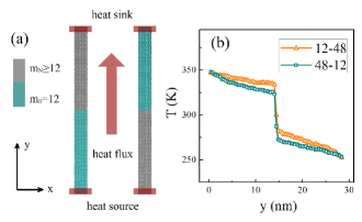
We carry out the molecular dynamics simulations of the heat conduction in two rectangle graphene flakes with zig-zag edges along the x-axis and armchair edges along the y-axis. The graphene flakes are shown in Fig. 1(a). They are both 288 Å long and 21 Å wide. The heat sources and heat sinks are covered by red boxes with 100 carbon atoms. The outmost edges of the heat sources/sinks are frozen. It corresponds to fixed boundary conditions in the y-axis. Periodic boundary condition is used along the x-axis. The atomic mass of the intact carbon atoms is and they are drawn in cyan. The atomic mass of the mass-loaded carbon atoms is and they are drawn in silver. The upper half region of the first graphene flake in Fig. 1(a) is mass-loaded, thus we label it as the as the graphene flake. Similarly we label the second one in Fig. 1(a) as the graphene flake. The heat flux runs along the graphene flake is equivalent to the reversed heat flux runs along the graphene flake. Thermal conduction process is investigated by imposing the same heat flux along the two graphene flakes. It is much more convenient later to compare the temperature profiles since the heat sources and heat sinks are in the same direction. We use the same reactive empirical bond-order (REBO) potential19.rebo (19) as implemented in the LAMMPS20.lammps (20) code to simulate the anharmonic coupling between the carbon atoms. Equations of motions are integrated with velocity Verlet algorithm with the minimum timestep fs.
First the graphene flakes are equilibrated at a constant temperature T=300 K in the Nose-Hoover thermostat by 0.75 ns. After that the heat flux is imposed. It is realized by the energy and momentum conserving velocity rescaling algorithm developed by Jude and Jullien21.Jund (21). A constant rate of kinetic energy is added in the heat source and removed in the heat sink at each time step . The heat flux is calculated as . It is widely used to study the interfacial heat conduction in different materials22.j1 (22, 23, 24). We divide the graphene flakes by several 4 Å long slabs along the y-axis to obtain the temperature profiles. Each slab contains about 60-70 carbon atoms. The local temperature in each slab is calculated from the averaged kinetic energy of the carbon atoms. The temperature profiles are averaged over every 100 ps after the heat flux is imposed. The whole nonequilibrium simulation process covers 3 ns and the last 1 ns is utilized as the steady state since the temperature profiles do not change much. Thermal conductivity of the whole graphene flake is calculated by the Fourier’s Law:
| (1) |
Here is the heat flux, is the cross section of the heat transfer defined by the product of the width and the thickness of the graphene flakes. The thickness of the graphene flake is usually considered as the bond length of the carbon atoms and it is taken as 1.4 Å in our computation25.thickness1 (25, 26). () is the temperature (distance) difference between the two ends on the graphene flake. Thermal conductivity G represents the thermal conducting capacity of the whole graphene flake. eV/ps is selected as the unit for the heat flux, Å is selected as the unit for the width and thickness, K is selected as the unit for the temperature. W/mK is selected as the unit for the thermal conductivity, so the associated numerical results are converted to this unit.
In Fig. 1(b) we show the typical temperature profiles of the two graphene flakes. Here and eV/ps are implemented. A sudden temperature drop is observed near the mass interface. It indicates that the mass interface behaves like a strong thermal resistive boundary. In Fig. 1(b), it also shows that although the temperature profiles are different in the two graphene flakes, but the temperature differences between the two ends are the same. The temperature difference in the graphene flake is 94.0 K and the temperature difference in the graphene flake is 93.8 K. Thus the thermal conductivity G of the two graphene flakes are the same. It indicates that even for such a large temperature difference, there is still no observable thermal rectification effect. The and the graphene flakes have the same thermal conducting capacity and the heat flux runs equivalently without preferred direction.
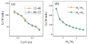
In order to further confirm the result that there is no thermal rectification effect brought by the mass interface in the graphene flakes, the dependence of thermal conductivity upon the heat flux and the mass difference ratio are studied. First we keep the mass difference ratio invariant and vary the heat flux from 0.15 to 0.5 eV/ps. In Fig. 2(a) we show the dependence of thermal conductivity upon the heat flux. Thermal conductivity is almost the same in the two graphene flakes. It indicates that there is no thermal rectification effect by using different value of heat flux. Meanwhile it is found that thermal conductivity is decreasing with the heat flux. For eV/ps, the thermal conductivity is about 110 W/mK. For eV/ps, it is reduced to 38 W/mK which is about 35% of the original value. It indicates that interfacial scattering is enhanced by the amount of heat flux and the effect might be taken into consideration in real application.
Second we keep the heat flux eV/ps invariant and vary the mass difference ratio from 1 to 5. Here stands for the graphene flake without the mass interface. In Fig. 2(b) we show the dependence of thermal conductivity upon the mass difference ratio. Thermal conductivity is almost the same in the two graphene flakes. It indicates there is no thermal rectification effect by using different mass difference ratio. Meanwhile it is found that thermal conductivity is greatly decreased by the mass interface. The thermal conductivity of the graphene flake without the mass interface is about 269 W/mK. When the mass interface is implemented (), it is reduced to 45 W/mK. It is only about 16% of the original value. Here it provides a possible route to tune the thermal behavior of graphene. The mass interface can be implemented by two methods. One is to load external heavy and thermal insulating molecules upon the carbon atoms11.science (11, 12, 13, 14). The other one is to use different ratio of isotope substitutions27.iso (27, 28, 29) which is demonstrated possible in experiment by chemical vapor deposition growth of graphene on metal30.iso (30).
The heat conduction results suggest that inhomogeneous mass interface cannot lead to thermal rectification effect in graphene. In the above simulations, the anharmonic coupling between the carbon atoms is kept constant and there is no geometric deformation by using periodic boundary condition along the width. Therefore just like carbon nanotubes, the asymmetry of interaction potential and the asymmetry of geometric shape also do not contribute in the graphene flakes. Furthermore, the interfacial scattering of solitons in surmised to be responsible for the thermal rectification effect in carbon nanotubes11.science (11). So in order to understand the absence of thermal rectification effect, it is necessary to study the interfacial scattering of solitons in graphene. Recently, subsonic NLS (Nonlinear Schrödinger) equation described solitons are found in graphene31.zhao Jigger (31). They preserve their identities in propagation and exhibit strong interactions and phase shifts in collision. Their energy reflection rates between the two regions with different mass are needed if one tends to know whether the solitons would bring rectification effect in the interfacial scattering process32.JPS (32, 33, 34).
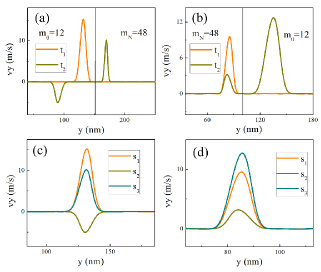
Here we first generate a longitudinal soliton in a 485 nm long graphene flake with atomic mass .The chirality of the graphene flake is the same as the two graphene flakes in Fig. 1(a). In the curve t1 of Fig. 3(a), we show the longitudinal velocity (vy) distribution of the carbon atoms before the interfacial scattering. The soliton is set as the incident soliton and its amplitude is positive. After that we change the atomic mass of the carbon atoms ahead of the solitons to be to set up a mass interface. The barrier line in the middle of Fig. 3(a) separates the graphene flake into two regions. The atomic mass of the left region is intact () and the atomic mass of the right region is mass-loaded (). The interfacial scattering from the to the region happens when the incident soliton hits the mass interface. In the curve t2 of Fig. 3(a), we show the longitudinal velocity distribution of the carbon atoms after the interfacial scattering. The incident soliton is scattered to a transmitted soliton and a reflected soliton. The amplitude of the transmitted soliton is positive and the amplitude of the reflected soliton is negative in the scattering. Similarly we obtain the interfacial scattering from the to the region. In Fig. 3(b) we show that the amplitude of the transmitted soliton is positive and the amplitude of the reflected soliton is also positive in the scattering. The scattering results indicate that the amplitude of the reflected soliton is dependent upon the incident direction. It is negative in the scattering and positive in the scattering. Such behavior of the reflected soliton has also been obtained in the interfacial scattering of similar NLS solitons in 1D nonlinear chain32.JPS (32). It represents a different kinetic behavior of the NLS solitons from the KdV solitons which have no reflected solitons in the scattering.
There is a rescaling relation between the width of the scattered solitons. The propagating velocity of a soliton in the region is 20 km/s and in the section31.zhao Jigger (31) is . Since the scattering time is very short thus we can neglect the amplitude dependent parameters in the formula to estimate . In the scattering can be estimated by the width of the incident soliton as . So the width of the reflected soliton in the region and the width of transmitted soliton in the region are:
| (2) |
| (3) |
Similar relations can be obtained in scattering. The width of the reflected soliton in the region and the width of transmitted soliton in the region are:
| (4) |
| (5) |
In Fig. 3(c) and Fig. 3(d) we show the width rescaling relations between the scattered solitons. The width of the reflected soliton s2 and the transmitted soliton s3 are rescaled well according to the width of the incident soliton s1.
In order to understand the role of solitons play in the heat conduction process, the energy reflection rate is needed. We measure the energy and the momentum of a soliton in graphene as the aggregated momentum and energy of all the carbon atoms along the width of the soliton35.zhao (35, 36):
| (6) |
Here only the carbon atoms with m/s are counted. The widths of the scattered solitons also could be estimated by the rescaling relation in Eq. (2)-(5). When the energy and the momentum of the scattered solitons are obtained, the energy reflection rate and the momentum reflection rate are defined as:
| (7) |
Here and are the energy and the momentum of the incident soliton. and are the energy and the momentum of the reflected soliton.
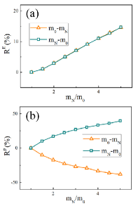
In Fig. 4 we show the dependence of the energy and the momentum reflection rate upon the mass difference ratio. In Fig. 4(a) it shows that the energy reflection rates in the and the scattering are the same. In Fig. 4(b) it shows that the momentum reflection rates are asymmetric. In the () scattering, the negative (positive) momentum reflection rates are obtained. The results explain the absence of thermal rectification in graphene: although the momentum reflection rate is dependent upon the incident direction, the energy reflection rate is directional independent. The same amount of energy would be reflected by the mass interface, thus it brings no reflection effect in the heat conduction process.
Here we point out that the role of the KdV solitons surmised by Chang et al. plays in thermal rectification is still under heavy debate01.Casati.Nature (1, 12, 13, 14, 37). First, an extremely large excitation is needed to generate the supersonic KdV solitons. In carbon nanotubes, they are surmised to be generated by the collision of electrons, ultrashort laser light or strong compressions38.cnt kdv (38, 39). So it is almost impossible that in the heat conduction process at room temperature, the KdV solitons could be generated. So far there is still no direct evidence of the supersonic KdV solitons in either carbon nanotubes or graphene flakes. Second, Chang et al. suggest the preferred direction of the heat flux is from the heavy to the light mass regions by considering KdV solitons11.science (11). However in the MD simulations of carbon nanotubes, it shows that the preferred direction is from the light to the heavy mass regions. It contradicts the existence of the KdV solitons in carbon nanotubes12.cnt1 (12, 13, 14). In our molecular dynamics simulations of graphene flakes, there is no thermal rectification effect in the heat conduction process. The result is also against the existence of the KdV solitons in graphene. Third, the square of the amplitudes is used to estimate the energy of a soliton by Chang et al. However, the dependence of energy upon the amplitude is far more complicated35.zhao (35, 36). Thus the width of a soliton is also necessary to be taken into consideration in order to measure the amount of energy.
In summary, the inhomogeneous mass interface cannot bring thermal rectification effect in graphene. The absence of rectification effect is confirmed by studying different heat flux and mass difference ratio. The microscopic mechanism is explained by the interfacial scattering of solitons in graphene which reveals directional independent energy reflection rate. Our results imply that the mass interface or the mass gradient which is a combination of multiple mass interfaces cannot be applied to design graphene based thermal rectifiers.
Acknowledgements.
We thank Jiao Wang and Yong Zhang for helpful discussion and preparing of the manuscript. This work was supported by National Natural Science Foundation of China(#10775115 and #10925525).References
- (1) Casati G 2007 Nature Nanotech. 2 23
- (2) Roberts N A and Walker D G 2011 Int. J. Therm. Sci. 50 648
- (3) Terraneo M, Peyrard M and Casati G 2002 Phys. Rev. Lett. 88 094302
- (4) Li B, Wang L and Casati G 2004 Phys. Rev. Lett. 93 184301
- (5) Hu B, Yang L and Zhang Y 2006 Phys. Rev. Lett. 97 124302
- (6) Wu G and Li B 2007 Phys. Rev. B. 76 085424
- (7) Wu G and Li B 2008 J. Phys.: Condens. Matter. 20 175211
- (8) Hu J, Ruan X and Chen Y P 2009 Nano Lett. 9 2730
- (9) Yang N, Zhang G and Li B 2009 Appl. Phys. Lett. 95 211908
- (10) Cheh J and Zhao H 2011 e-print arXiv:1108.5270v1 [cond-mat.mtri-sci]
- (11) Chang C W, Okawa D, Majumdar A and Zettl A 2006 Science 314 1121
- (12) Alaghemandi M, Algaer E, Bohm M C and Müller-Plath F 2009 Nanotechnology 20 115704
- (13) Alaghemandi M, Leroy F, Algaer E, Bohm M C and Müller-Plath F 2010 Nanotechnology 21 075704
- (14) Alaghemandi M, Leroy F, Algaer E, Müller-Plath F and Bohm M C 2010 Phys. Rev. B. 81 125410
- (15) Geim A K and Novoselov K S 2007 Nat. Mater. 6 183
- (16) Geim A K 2009 Science 324 1530
- (17) Balandin A A, Ghosh S, Bao W, Calizo I, Teweldebrhan D, Miao F, et al. 2008 Nano Lett. 8 902
- (18) Cai W, Moore A L, Zhu Y, Li X, Chen S, et al. 2010 Nano Lett. 10 1645
- (19) Brenner D W et al. 2002 J Physics: Condensed Matter. 14 783
- (20) Plimpton S 1995 J. Comput. Phys. 117 1
- (21) Jund P and Jullien R 1999 Phys. Rev. B. 59 13707
- (22) Hu M, Keblinski P and Li B 2008 Appl. Phys. Lett. 92 211908
- (23) Hu M, Keblinski P and Schelling P K 2009 Phys. Rev. B. 79 104305
- (24) Liang Z and Tsai H L 2011 Phys. Rev. E. 83 041602
- (25) Guo Z, Zhang D and Gong X G 2009 Appl. Phys. Lett. 95 163103
- (26) Wei N, Xu L, Wang H Q and Zheng J C 2011 Nanotechnology 22 105705
- (27) Ouyang T, Chen Y P, Yang K K and Zhong J X 2009 Europhys. Lett. 88 28002
- (28) Hu J, Schiffli S, Vallabhaneni A, Ruan X and Chen Y P 2010 Appl. Phys. Lett. 97 133107
- (29) Balasubramanian G, Puri I K, Bohm M C and Leroy F 2011 Nanoscale. 3 3714
- (30) Li X, Cai W, Colombo L and Ruoff R S 2009 Nano Lett. 9 4268
- (31) Cheh J and Zhao H 2011 e-print arXiv:1107.3696v2 [cond-mat.mtrl-sci]
- (32) Iizuka T and Wadati M 1992 J. Phys. Soc. Jpn. 61 3077
- (33) Nesterenko V F, Daraio C, Herbold E B and Jin S 2005 Phys. Rev. Lett. 95 158702
- (34) Vergara L 2005 Phys. Rev. Lett. 95 108002
- (35) Wen Z and Zhao H 2005 Chin. Phys. Lett. 22 1341
- (36) Zhao H, Wen Z, Zhang Y and Zheng D 2005 Phys. Rev. Lett. 94 025507
- (37) Pereira E 2011 Phys. Rev. E. 83 031106
- (38) Astakhova T Y, Gurin O D, Menon M and Vinogradov G A 2001 Phys. Rev. B. 64 035418
- (39) Astakhova T Y, Menon M and Vinogradov G A 2004 Phys. Rev. B. 70 125409