Bottle microresonator with actively stabilized evanescent coupling
Abstract
The evanescent coupling of light between a whispering-gallery-mode bottle microresonator and a sub-wavelength-diameter coupling fiber is actively stabilized by means of a Pound-Drever–Hall technique. We demonstrate the stabilization of a critically coupled resonator with a control bandwidth of 0.1 Hz, yielding a residual transmission of for more than an hour. Simultaneously, the frequency of the resonator mode is actively stabilized.
Microresonators are key elements in a wide range of applications such as microlasers, cavity quantum electro dynamics (CQED), cavity opto-mechanics, and optical signal processing Vahala:2003aa ; Ilchenko:2006 ; Kippenberg:2008 ; Notomi:2010 . In this context, whispering-gallery-mode (WGM) microresonators have attained special interest since they combine ultra-high quality factors and small mode volumes Kippenberg:2004aa with the ability to evanescently couple light into and out of the resonator with very high efficiency using evanescent couplers such as prisms, angle-polished fibers and micro-tapered optical fibers Knight:1997aa ; Spillane2003a ; Matsko2006 . WGM resonators are monolithic dielectric structures that confine light near the resonator surface by continuous total internal reflection Matsko2006 . They have been realized in several different designs, such as microspheres, microtoroids, microdisks Vahala:2003aa ; Matsko2006 , and, recently, bottle microresonators Sumetsky04 ; Louyer2005 ; SenthilMurugan:09 ; Pollinger2009 (see inset to Fig. 1 (a)). While being conceptually similar to traditional WGM resonators and sharing many properties, bottle microresonators have the additional advantage of combining the tunability typical to Fabry-Pérot resonators. Light is coupled into such resonators by matching the phase and frequency of the field of the evanescent coupler with the WGM while the coupling strength is set by their spatial overlap Knight:1997aa . This coupling strength determines the intracavity intensity for a given input power. The latter is maximized in the case of so-called critical coupling, i.e., when the losses induced by the evanescent coupler equal the intrinsic round trip losses in the cavity. In order to maintain a stable intracavity intensity, the gap between an evanescent coupler and a WGM microresonator must remain stable within a few tens of nanometers. So far, evanescent coupling has mostly relied on the passive stability of the setup. In practice, however, long-term drifts on the nanometer scale will occur.
At critical coupling, the intensity of the light field transmitted through the evanescent coupler past the resonator is not a monotonous function of the coupling strength but goes through a minimum Spillane2003a . Thus, the transmitted intensity cannot be directly used as an error signal for stabilizing the coupling gap. Instead, a modulation technique can be employed in order to gain information about the sign of the change in coupling strength.
In this letter, we present a novel method, based on the Pound-Drever–Hall (PDH) modulation technique Drever:1983aa , to actively stabilize the evanescent coupling between a bottle microresonator and the sub-wavelength-diameter waist of a tapered optical fiber (coupling fiber). The idea of the scheme is to use an off-resonant PDH signal to sense the linewidth broadening of the bottle mode which is proportional to the coupling strength. This scheme avoids any mechanical modulation of the coupling gap size Wilcut:09 and its bandwidth can in principle reach the dynamical limits of the mechanical coupling setup.
The amplitude of the PDH error signal for light of frequency is given by the relation Black2001
| (1) |
where is the phase modulation frequency which also determines the spectral separation of the carrier and the sidebands. For a WGM resonator, the amplitude transmission through the coupling fiber, , also depends on the coupling gap and is given by Haus:84aa
| (2) |
Here, and are the intrinsic linewidth (FWHM) and the resonance frequency of the resonator mode, respectively. The coupling fiber induces a gap-dependent linewidth broadening which scales as , where is the evanescent field decay length.
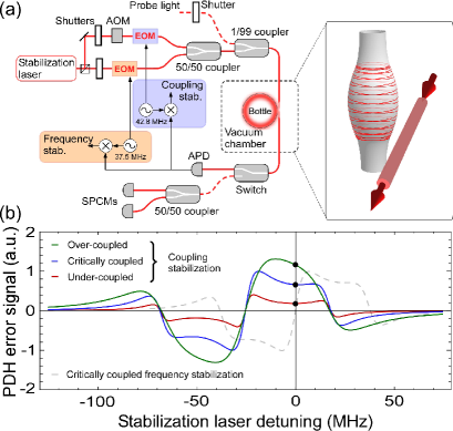
Figure 1 (b) shows the calculated PDH signal for different coupling regimes. For decreasing coupling gaps, the linewidth increases and there is a corresponding increase of the off-resonant PDH signal (solid black circles) which therefore behaves monotonically for a large range of gap sizes. In order to generate the off-resonant PDH signal, a constant resonator–laser detuning is required. The experimental setup, shown in Fig. 1 (a), therefore uses two laser beams derived from an external cavity diode laser (50 kHz linewidth) which are phase modulated using electro-optic modulators (EOMs). For one laser beam ( MHz), the carrier is resonant with the bottle mode and is used for stabilizing the frequency of the resonator OShea2010 . Simultaneously, a second, laser beam with a constant carrier frequency detuning of 20–25 MHz relative to the resonance frequency of the bottle mode is used to create the off-resonant PDH signal for the coupling stabilization ( MHz). Both beams are sent through the coupling fiber and the light transmitted past the resonator is detected with an avalanche photodiode (APD). The APD signal is split and mixed with the modulation frequencies and , respectively, to create the two PDH signals.
The bottle microresonator has a diameter of 38 m and is made from a silica glass fiber in a heat-and-pull-process as described in Pollinger2009 . In this work, we excite bottle modes with linewidths of 8–15 MHz at critical coupling, corresponding to intrinsic quality factors of –. We tune the bottle mode frequency via mechanical strain, applied to the glass fiber carrying the resonator by means of a shear piezo stack. The coupling fiber is mounted on a positioning stage that enables sub-nanometer control of the coupling gap. The coupling setup is placed in a vacuum chamber with a background pressure of mbar, compatible with the requirements of a cold-atom CQED experiment oshea:2011 . We note, however, that our scheme should work equally well under ambient conditions.
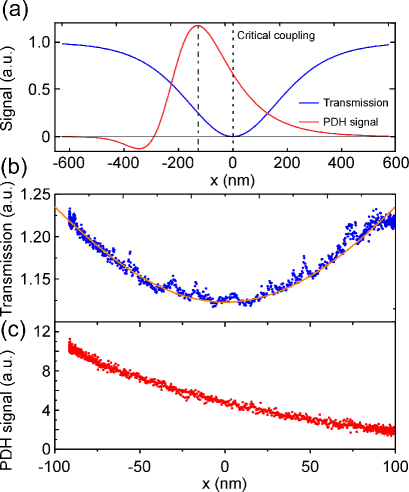
Figure 2 (a) shows a plot of the calculated intensity transmission and of the calculated off-resonant PDH signal as a function of the coupling gap for our experimental parameters. As discussed above, , vanishes at critical coupling and all light is dissipated in the resonator. The off-resonant PDH signal has the desired monotone behavior for gap variations around critical coupling and is therefore a suitable error signal for coupling stabilization. For decreasing coupling gaps, the mode linewidth can exceed the modulation frequency. If the detuning from resonance is half the modulation frequency, , this results in a rolloff of the PDH signal for a coupling gap (see dash-dotted line in Fig. 2 (a)), determined by the condition . Thus, for a given -factor, can be shifted over a large range of values by appropriate choice of .
In order to experimentally verify our simulations, we scanned the coupling gap around the critical coupling value in open-loop mode and recorded simultaneously the intensity transmission detected by the APD and the off-resonant PDH signal, see Fig. 2 (b), (c). The transmission and the off-resonant PDH signal are in good qualitative agreement with the theoretical predictions in Fig. 2 (a). In particular, the PDH signal is monotonous around critical coupling.
We verify the correct operation of the stabilization scheme by using a lock–probe method: The system is cyclically stabilized for one second and subsequently, the transmission is probed for 5 ms with a weak (pW), resonant laser beam (see Fig. 1 (a)). During the probing, the frequency and coupling stabilization beams (with about 20 nW in each beam) are turned off with shutters and the probe transmission is detected with two single photon counting modules (SPCMs).
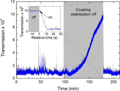
Figure 3 shows the corresponding probe transmission, recorded over several hours. It can be seen that the system remains stabilized at the critical coupling point with a very low average intensity transmission of while the standard deviation is . After 90 minutes, the coupling stabilization is turned off while the frequency stabilization is still operating. In the following, drifts of the coupling gap cause the transmission to change, reaching a value of 0.1 after 70 min. At that point, the coupling stabilization is switched on again and the stabilization scheme successfully restores the critical coupling condition. The inset of Fig. 3 shows a zoom of the recapturing process. From this signal, we estimate the bandwidth for the stabilization technique to be 0.1–0.2 Hz. This value is limited by the time constant of a low pass filter that has been inserted into the control loop in order to avoid the excitation of mechanical resonances of the coupling setup. The temporary transmission fluctuations around 50 min occur on a timescale of 1–7 s and are assigned to mechanical vibrations of the coupling setup probably from seismic, thermal, or acoustic noise at frequencies exceeding the stabilization bandwidth.
From the transmission noise in Fig. 3, we furthermore determine the fluctuations of the coupling gap. At critical coupling, these fluctuations cause asymmetric noise that can be differentiated from noise sources that yield a symmetric distribution like, e.g., detector noise. From this analysis, we estimate the rms-fluctuation of the gap to be nm in the frequency range up to 200 Hz.
In conclusion, our method holds great potential for applications involving evanescently coupled WGM microresonators if a high coupling stability is required over an extended period of time, especially in the case of critical coupling. Such applications range, e.g., from optical signal processing Ilchenko:2006 ; Pollinger:2010 and CQED with WGM resonators Aoki:2006aa to single molecule detection with cavities in bio-sensing Armani2007 . Moreover, our technique can be equally well applied to other evanescent coupling schemes Matsko2006 and other types of evanescently coupled cavities, such as, e.g., photonic crystals Srinivasan2004 .
We gratefully acknowledged financial support by the DFG (Research Unit 557), the Volkswagen Foundation (Lichtenberg Professorship), and the ESF (EURYI).
References
- (1) K. J. Vahala, Nature 424, 839 (2003), and references therein.
- (2) V. Ilchenko and A. Matsko, Selected Topics in Quantum Electronics, IEEE Journal of 12, 15 (2006).
- (3) T. J. Kippenberg and K. J. Vahala, Science 321, 1172 (2008).
- (4) M. Notomi, Rep. Prog. Phys. 73, 096501 (2010).
- (5) T. J. Kippenberg, S. M. Spillane, and K. J. Vahala, Appl. Phys. Lett. 85, 6113 (2004).
- (6) J. C. Knight, G. Cheung, F. Jacques, and T. A. Birks, Opt. Lett. 22, 1129 (1997).
- (7) S. Spillane, T. Kippenberg, O. Painter, and K. Vahala, Phys. Rev. Lett. 91, 043902 (2003).
- (8) A. Matsko and V. Ilchenko, IEEE J. Sel. Top. Quant. 12, 3 (2006).
- (9) M. Sumetsky, Opt. Lett. 29, 8 (2004).
- (10) Y. Louyer, D. Meschede, and A. Rauschenbeutel, Phys. Rev. A 72, 1 (2005).
- (11) G. S. Murugan, J. S. Wilkinson, and M. N. Zervas, Opt. Express 17, 11916 (2009).
- (12) M. Pöllinger, D. O’Shea, F. Warken, and A. Rauschenbeutel, Phys. Rev. Lett. 103, 053901 (2009).
- (13) R. W. P. Drever, J. L. Hall, F. V. Kowalski, J. Hough, G. M. Ford, A. J. Munley, and H. Ward, Appl. Phys. B 31, 97 (1983).
- (14) E. Wilcut Connolly, “Experiments with toroidal microresonators in cavity QED”, Ph.D. thesis, California Institute of Technology (2009).
- (15) E. D. Black, Am. J. Phys. 69, 79 (2001).
- (16) H. A. Haus, Waves and fields in optoelectronics, vol. 1 (Prentice-Hall New Jersey, 1984).
- (17) D. O’Shea, A. Rettenmaier, and A. Rauschenbeutel, Appl. Phys. B 99, 623 (2010).
- (18) D. O’Shea, C. Junge, M. Poellinger, A. Vogler, and A. Rauschenbeutel, Appl. Phys. B (to be published), eprint: arXiv:1105.0330 (2011).
- (19) M. Pöllinger and A. Rauschenbeutel, Opt. Express 18, 17764 (2010).
- (20) T. Aoki, B. Dayan, E. Wilcut, W. P. Bowen, A. S. Parkins, T. J. Kippenberg, K. J. Vahala, and H. J. Kimble, Nature 443, 671 (2006).
- (21) A. M. Armani, R. P. Kulkarni, S. E. Fraser, R. C. Flagan, and K. J. Vahala, Science 317, 783 (2007).
- (22) K. Srinivasan, P. Barclay, M. Borselli, and O. Painter, Phys. Rev. B 70, 081306 (2004).