Current address: ]Materials Science Division, Argonne National Laboratory
Enhancement of vortex pinning in superconductor/ferromagnet bilayers via angled demagnetization
Abstract
We use local and global magnetometry measurements to study the influence of magnetic domain width on the domain-induced vortex pinning in superconducting/ferromagnetic bilayers, built of a Nb film and a ferromagnetic Co/Pt multilayer with perpendicular magnetic anisotropy, with an insulating layer to eliminate proximity effect. The quasi-periodic domain patterns with different and systematically adjustable width , as acquired by a special demagnetization procedure, exert tunable vortex pinning on a superconducting layer. The largest enhancement of vortex pinning, by a factor of more than 10, occurs when m is close to the magnetic penetration depth.
pacs:
74.25Ha, 74.25Qt, 74.78Db, 74.78FkOne of the most important parameters for the application of type II superconductors is the critical current density, . To achieve high it is necessary to pin vortices, which exist in the mixed state. The usual method for pinning vortices utilizes microscopic defects in the material that locally suppress superconductivity and trap normal vortex cores. Magnetic pinning (MP) instead relies on the electromagnetic interaction between the vortex magnetic field and the stray field generated by the magnetic texture in the vicinity of the superconductor surface velez ; Luks ; aladysh . Since magnetic pinning acts on a length scale comparable to the penetration depth, , it is dominant at temperatures close to the superconducting transition temperature, , where pinning by defects becomes ineffective.
A novel magnetic pinning method utilizes a planar superconductor(S)/ferromagnet(F) bilayer (SFB) separated by a thin insulating layer, which eliminates proximity effects Luks ; aladysh ; velez ; bula ; bezpy . As previously suggested, the magnetic domains in the F layer create pinning centers for the vortices in the S layer so that tuning the domain structure can result in tuning bula ; bezpy . While the principle of magnetic pinning in the SFB’s has been extensively discussed theoretically Luks ; aladysh ; bula ; bezpy ; Milo ; erdin ; sonin ; laiho ; kayali ; erdin2 and demonstrated experimentally garcia ; zhang ; jan ; Lange ; Cieplak ; Cieplak2 ; feig ; vv ; vv2 ; belkin ; karapetrov ; leyizhu ; vv3 ; iava ; vis , the magnitude of the pinning enhancement thus far reported has been modest with a factor of no more than 3, and sometimes even suppression of pinning has been described feig . Furthermore, it has not been feasible to compare various magnetic pinning results, since the different SFB bilayers used in these studies would render such comparison impractical.
In this work we show that it is possible to systematically vary and achieve much higher enhancement of in planar SFB’s with Nb as the S layer and Co/Pt multilayer with perpendicular magnetic anisotropy (PMA) as the F layer. The PMA in the F layer assures a direct effect in magnetic pinning that is not well defined in F layer with in-plane anisotropy. Using a single SFB, we use a special demagnetization method to continuously tune the width of the domains, , in the quasi-periodic stripe domain pattern of the F layer with equal domain, and observe the dramatic effect of tuning on vortex pinning using the global (SQUID) and the local (Hall sensors) magnetometry measurements. Using a single SFB with an identical S layer, we have quantitatively determined enhancement as a result of changing domain width. We have observed enhancement in excess of 10.
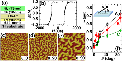
The SFB’s were grown by sputtering at room temperature on Si(100) substrates with the same sequence of Si(10)/Pt(10)/[Co(0.6)/Pt(0.3)]8/Si(10)/Nb(), with the thickness denoted in nanometers in parentheses (Fig. 1(a)). The Si(10) layer between [Co/Pt]8 and Nb eliminates the proximity effect. Two samples (A and B) with nominally = 76 nm were studied by magnetometry, whereas the third sample (C) with = 20 nm with an additional Si(10) protective layer on the top was used to extract the vortex activation energy from transport experiment, as described separately leyizhu . All three samples (A, B, C) display a square hysteresis loop in the normal state, with the coercive fields at 10 K of = 720 Oe (A), 775 Oe (B), and 750 Oe (C) (Fig. 1(b)). From magnetoresistance measurements of SFB magnetized to saturation we extract the superconducting parameters of the Nb layer of = 8.56K (A), 8.42 K (B), and 7.95 K (C), coherence length, 14.5 nm (A), 12.4 nm (B), and 12 nm (C), and estimated Ginzburg-Landau parameter for dirty-limit superconductors tinkham of 3.8 (A), 5.2 (B), and 5.6 (C).
A well known method to acquire multi-domains with equal domains in an F layer with PMA is AC demagnetization with field perpendicular to the film plane. However, we can also obtain domain pattern with equal domains but with different width by demagnetization with an AC magnetic field at an angle with the sample plane. Figs. 1(c)-(e) show MFM images of sample A at 300 K for various ’s. Indeed, the images reveal equal amount of positive and negative domains, but the average width increases with increasing . From these MFM images, using two-dimensional Fourier analysis we extract the mean value of and the standard deviation, as shown in Fig. 1(f). Demagnetization at results in a similarly small 0.31 - 0.35 m for all samples, but the width increases with with a more rapid growth of at small . This increase of with is caused by the fact that in ferromagnets with PMA the magnetic moments are out-of-plane in the uniform domain area but with an in-plane component within the domain walls. With increasing the demagnetization field has a decreasing in-plane component, which tends to align less spins in-plane and thus creates less domain walls, resulting in a larger leyizhu . Based on the -dependence of we estimate that the domains may shrink upon cooling down to by less than 10%.
As alluded to earlier, the samples A and B are nominally the same and yet they display slightly but noticeably different superconducting transition temperature , coercivity , coherence length , and the Ginzburg-Landau parameter . As shown in Fig. 1, the width of the domains for samples A and B is also measurably different. These are unavoidable sample-to-sample variations for SFB’s at these small layer thicknesses, and underscore the importance of performing experiment with -tuning on a single SFB sample.
Figure 2(a) shows the hysteresis loops for sample B measured in a SQUID magnetometer. The loops were measured in a small external magnetic field, , between -90 Oe and 90 Oe, after setting the domain pattern by AC demagnetization at angle followed by cooling the sample just below . The cycling of the small magnetic field has no effect on the domain pattern, and no relaxation of magnetization in the superconducting state has been observed. Also included in Fig. 2 (a), with the narrowest hysteresis loop, is the sample with a saturated F layer. The width of the hysteresis loop, , increases dramatically as a result of demagnetization indicating a large enhancement of vortex pinning by the magnetic domains. The largest is at = 0∘, when is small, and decreases as grows with increasing . Even at = 90∘ with the largest of about 0.7 m, is still much larger than that of the saturated F layer. We have also observed a slight asymmetry in the hysteresis curve, particularly at large .
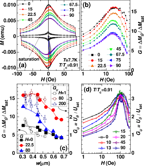
To estimate the enhancement of from the global magnetometry results one needs a model of the critical state with a specific dependence of on the magnetic induction . The simplest is the Bean model, which assumes to be independent of , leading to the well-known prediction of poole . Under this model, the ratio reflects the enhancement of induced by the domain pattern as set by the demagnetization, where and are the hysteresis loop width for sample demagnetized at and that of the saturated F layer respectively. The dependence of on is shown in Fig. 2(b) on a semi-logarithmic scale, omitting the same dependence for negative . The dependencies are similar for various . The largest value of is observed for small in the intermediate field range of Oe. The value of at all fields decreases with increasing of , but still retains a high peak value of at . Fig. 2(c) shows the dependence of (left scale, full data points) on the actual domain width for three representative field values, at the peak ( Oe), low- (), and high- ( Oe). The is reduced almost linearly with increasing at low- (bottom curve). At the peak (top curve) the remains large for narrow domains, and starts to decrease rapidly for exceeding about 0.45 m. The high- behavior (middle curve) is intermediate, with the weak suppression of for small , and more rapid suppression for large .
To obtain model-independent assessment of , we need microscopic measurement of at various locations. For this purpose we employ a linear array of miniature Hall sensors to probe locally the dependence of on the distance from the sample edge. The local magnetic field is defined as , and is obtained from the relation brandt . From sample A, we cut a 240 m wide strip and placed a line of 10 sensors, each of which m2 in size and 20 m apart, across the strip. An additional sensor, placed a few mm outside the sample edge, is used to measure the actual applied field as shown in Fig. 3(a). The is registered simultaneously by Hall sensors while is swept from 0 up to +100 Oe, and from +100 Oe to -100 Oe. The evolution of during the second part of the sweep is shown in Figs. 3(b)-(c) for 0∘ and 90∘. As is swept, the flux remains trapped inside, so that increases in the sample center, eventually reaching a maximum of 41 Oe () or 27 Oe () just after changes sign to negative, while in the saturated sample 5.5 Oe is observed. The calculated has a maximum at approximately the same , reaching about Am-2 for , and Am-2 for , while it is only Am-2 in the saturated sample. This confirms the conclusion of strong pinning enhancement, particularly for narrow domains at . Interestingly, Figs. 3(b)-(c) reveal that the change of is much smoother during the sweep from +100 Oe to 0 than during the sweep from 0 to -100 Oe, where there are many sudden and large drops of across the whole sample. Such abrupt decrease of indicates the abrupt annihilation of flux over the large sample area. It is most likely triggered by the strong interaction between the positive flux still trapped inside and negative flux entering the sample. This effect likely contributes to the asymmetry of hysteresis seen in Fig. 2(a).
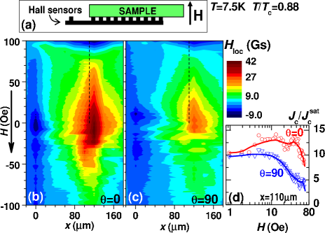
Figure 3(d) shows the ratio of to (where is in the saturated sample), calculated for m, the approximate position at which is the largest (along the dashed line in Figs. 3(b)-(c)). The calculation has been made for , since for negative is highly irregular because of the jumps of . As shown in Fig. 3(d), is higher for in the whole -range than that for , the same conclusion as that in Fig. 2(b), although the shape of , while generally similar to in Fig. 2(b), differs noticeably in details. This is not surprising because the local measurements using an array of Hall sensors are more susceptible to local irregularities of the flux penetration inside the narrow sample, while the global magnetometry measurement integrates over the large sample. Nevertheless, the most essential conclusion that pinning is strongest for narrow domains remains unchanged. Similar result is obtained at lower , but the maximal magnitude of the decreases, by about 17% at , and by 30% at .
The results clearly establish that the strongest pinning occurs at the smallest . This is due to several factors. The magnitude of the stray field at the domain center scales as maksimova , and moreover, the density of pinning centers also increases with decreasing . As a result, at low the vortices are most effectively pinned when is the smallest. An additional argument comes from the comparison of to the penetration depth, since this is the length scale of the vortex-domain interaction. The thickness of Nb in sample B is nm, slightly larger than nm. As increases, grows as , so at we obtain nm. However, at high one approaches the limit of , for which one should use the effective penetration depth, nm tinkham . While this higher limit is not quite reached here, it is likely that approaches, and perhaps even exceeds, the average domain width of nm for . Since in the quasi-ordered domain pattern there are areas in which is smaller than average, vortices cannot move freely along domains, thus enhancing the pinning. The value of grows with increasing , and the vortices flow more easily, thus diminishing the value of .
As shown in Fig. 2(b), for each value of , increases with reaching a maximum presumably when the vortex lattice becomes commensurate with the magnetic domain pattern. This is followed by a decrease of , when the vortex density exceeds that of the domain-induced pinning centers. Since the domain density decreases with increasing , the suppression of at high is weaker for smaller as shown by the blue triangles in Fig. 2(c).
The commensurability of vortex pinning can be advantageously observed using an ordered array of pinning centers, which lead to enhanced pinning at well-defined matching fields velez . In the SFBs the vortices are confined to the irregular domains of one sign. In the case of regular stripe domain pattern with the period single or multiple chains of vortices are pinned by each domain, as recently shown by scanning tunneling microscopy karapetrov . We have recently performed transport measurements on sample C demagnetized at different to capture different domain widths and we have inferred a similar chain-pinning phenomenon leyizhu . At sufficiently below the resistance is thermally activated, with the activation energy for vortex pinning, , enhanced by magnetic domains. The exhibits maxima at matching fields when narrow domains (small ) pin single vortex chains, and wider domains (large ) pin double vortex chains.
It is interesting to compare the activation energy from transport measurements on sample C leyizhu with the present data on sample B. From the transport results, we calculate the enhancement of induced by demagnetization at , using the parameter , where is for sample C demagnetized at , and is for saturated sample. The values of versus for several values of are shown in Fig. 2(d). One notes that and display strikingly similar dependence. Furthermore, both display the largest value at the smallest values of , decreasing monotonically with increasing . These systematic dependencies are illustrated in Fig. 2(c), where (filled symbols) and (open symbols) are for three representative fields, from the low field, peak, and high field regions ( = 0, 22.5, and 80 Oe for , and = 1, 80, and 200 Oe for , respectively). The qualitative similarity suggests a common origin, which is pinning of vortex chains by domains.
However, there are also noticeable differences between and . One notes that the peak in has a narrower width but it is located at a higher than that of , whereas reaches a maximum magnitude about 5 times larger than that of . Most of these differences are due to the different Nb thickness in sample B (76 nm) for and sample C (20 nm) for . In addition, sample B shows larger dispersion of . The dispersion of contributes directly to the broadening of matching field, while a thicker Nb layer leads to a progressive reduction of the domain-induced stray field (by up to about 25% on the other side of Nb maksimova ), and therefore reduction of the density of pinning centers across , shifting peak to smaller . The difference in magnitude between and is also mainly related to thickness. The strength of the magnetic interaction roughly depends on the ratio of the domain width , to the range of magnetic interaction, given approximately by . In the thicker sample B the magnetic interaction is stronger because is comparable to , whereas in the thinner sample C, is about 4 times larger so that the magnetic interaction is substantially reduced.
In conclusion, we have demonstrated a method to induce large enhancement of vortex pinning in the superconductor/ferromagnet bilayers using a ferromagnetic layer with perpendicular magnetic anisotropy. By demagnetizing the sample at an angle to the sample surface, we obtain domain patterns with equal domains but different domain width . This unique attribute allows a single bilayer to acquire different domain width to exert tunable vortex pinning on a superconducting layer. Magnetometry and local measurements using an arrays of Hall sensors show conclusively vortex pinning enhancement, by a factor of more than 10 at domain width of about 310 nm, much larger than previously obtained.
This work was supported by Polish MNiSW grant N202 058 32/1202, by NSF grant DMR05-20491, by the French-Polish Bilateral Program PICS 4916, and by the European Union within the European Regional Development Fund, through the Innovative Economy grant POIG.01.01.02-00-108/09.
References
- (1) M. Velez, J.I. Mart n, J.E. Villegas, A. Hoffmann, E.M. Gonz lez, J.L. Vicent and Ivan K. Schuller, J. Mag. Magn. Mat. 320, 2547 (2008).
- (2) I. F. Lyuksyutov and V. L. Pokrovsky, Adv. Phys. 54, 67 (2004).
- (3) A. Yu. Aladyshkin, A. V. Silhanek, W. Gillijns, and V. V. Moshchalkov, Supercond. Sci. Technol. 22, 053001 (2009).
- (4) L. N. Bulaevskii, E. M. Chudnovsky, and M. P. Maley, Appl. Phys. Lett. 76, 2594 (2000).
- (5) Yu. I. Bezpyatykh, W. Wasilevski, M. Gajdek, I. P. Nikitin and S. A. Nikitov, Sov. Phys. -Solid State 43, 1827 (2001).
- (6) M. V. Milosevic, S. V. Yampolskii, and F. M. Peeters, Phys. Rev. B 66, 174519 (2002).
- (7) S. Erdin, I. F. Lyuksyutov, V. L. Pokrovsky, and V. M. Vinokur, Phys. Rev. Lett. 88, 017001 (2002).
- (8) E. B. Sonin, Phys. Rev. B 66, 136501 (2002).
- (9) R. Laiho, E. Lahderanta, E. B. Sonin, and K. B. Traito, Phys. Rev. B 67, 144522 (2003).
- (10) M. A. Kayali and V. L. Pokrovsky, Phys. Rev. B 69, 132501 (2004).
- (11) S. Erdin, Phys. Rev. B 73, 224506 (2006).
- (12) A. Garcia-Santiago, F. Sanchez, M. Varela, and J. Tejada, Appl. Phys. Lett. 77, 2900 (2000).
- (13) X. X. Zhang, G. H. Wen, R. K. Zheng, G. C. Xiong, and G. J. Lian, Europhys. Lett. 56, 119 (2001).
- (14) D. B. Jan, J. Y. Coulter, M. E. Hawley, L. N. Bulaevskii, M. P. Maley, Q. X. Jia, B. B. Maranville, F. Hellman, and X. Q. Pan, Appl. Phys. Lett. 82, 778 (2003).
- (15) M. Lange, M. J. Van Bael, V. V. Moshchalkov, and Y. Bruynseraede, Appl. Phys. Lett. 81, 322 (2002).
- (16) M. Z. Cieplak, X. M. Cheng, C. L. Chien, and Hai Sang, J. Appl. Phys. 97, 026105 (2005).
- (17) M. Z. Cieplak Z. Adamus, A. Abal’oshev, I. Abal’osheva, M. Berkowski, X. M. Cheng, Hai Sang, C. L. Chien, Phys. Status Solidi C 2, 1650 (2005).
- (18) M. Feigenson, L. Klein, M. Karpovski, J. W. Reiner, and M. R. Beasley, J. Appl. Phys. 97, 10J120 (2005).
- (19) V. Vlasko-Vlasov, U. Welp, G. Karapetrov, V. Novosad, D. Rosenmann, M. Iavarone, A. Belkin, and W.-K. Kwok, Phys. Rev. B 77, 134518 (2008).
- (20) A. Belkin, V. Novosad, M. Iavarone, J. Pearson, G. Karapetrov, Phys. Rev. B 77, 180506 (2008).
- (21) V. K. Vlasko-Vlasov, U. Welp, A. Imre, D. Rosenmann, J. Pearson, and W. K. Kwok, Phys. Rev. B 78, 214511 (2008).
- (22) G. Karapetrov, M. V. Milošević, M. Iavarone, J. Fedor, A. Belkin, V. Novosad, and F. M. Peeters, Phys. Rev. B 80, 180506(R) (2009).
- (23) L. Y. Zhu, M. Z. Cieplak, and C. L. Chien, Phys. Rev. B 82, 060503(R) (2010).
- (24) V. Vlasko-Vlasov, U. Welp, W. Kwok, D. Rosenmann, H. Claus, A. A. Buzdin, and A. Melnikov, Phys. Rev. B 82, 100502(R) (2010).
- (25) M. Iavarone, A. Scarfato, F. Bobba, M. Longobardi, G. Karapetrov, V. Novosad, V. Yefremenko, F. Giubileo, and A. M. Cucolo, Phys. Rev. B 84, 024506 (2011).
- (26) C. Visani, P. J. Metaxas, A. Collaudin, B. Calvet, R. Bernard, J. Briatico, C. Deranlot, K. Bouzehouane, J. E. Villegas, arXiv:1107.1122v1.
- (27) M. Tinkham, Introduction to superconductivity, Dover Publications, 2004.
- (28) C. P. Bean, Phys. Rev. Lett. 8, 250 (1962); Rev. Mod. Phys. 36, 31 (1964).
- (29) E. H. Brandt, Phys. Rev. B 54, 4246 (1996).
- (30) G. M. Maksimova, R. M. Ainbinder, D. Y. Vodolazov, Phys. Rev. B 78, 224505 (2008).