Mechanically Compliant Grating Reflectors for Optomechanics
Abstract
We demonstrate micromechanical reflectors with a reflectivity as large as 99.4% and a mechanical quality factor as large as for optomechanical applications. The reflectors are silicon nitride membranes patterned with sub-wavelength grating structures, obviating the need for the many dielectric layers used in conventional mirrors. We have employed the reflectors in the construction of a Fabry-Perot cavity with a finesse as high as , and used the optical response to probe the mechanical properties of the membrane. By driving the cavity with light detuned to the high-frequency side of a cavity resonance, we create an optical antidamping force that causes the reflector to self-oscillate at 211 kHz.
pacs:
07.10.Cm,85.85.+j,05.40.Jc,42.50.Wk,42.50.Ct,42.79.Dj,78.67.Pt,07.60.LyOptical Fabry-Perot cavities employing mechanically compliant mirrors have been the subject of intense recent interest for their utility in quantum-limited position measurements Tittonen et al. (1999), creating nonclassical states of the optical cavity field and mirror Bose et al. (1997); Marshall et al. (2003), and attempting to optically cool fabricated mesoscopic systems into the quantum regime Arcizet et al. (2006); Thompson et al. (2008); Wilson et al. (2009); Gr oblacher et al. (2009). The optical cavity provides a means to interrogate the dynamics of a mechanical resonator with extremely high sensitivity, while simultaneously providing a large circulating optical power whose radiation pressure can be employed to alter the mechanics.
The ideal optomechanical element for such work combines low mass, high mechanical quality factor , and near-unity reflectivity. A small mass confers a large mechanical zero-point motion, which is directly proportional to the optomechanical coupling Bose et al. (1997), closely related to the standard quantum limit for continuous position detection Tittonen et al. (1999), and of particular relevance to experiments aimed at observing superposition states of the mirror Marshall et al. (2003). A high mechanical is desirable to minimize thermal noise in position detection Tittonen et al. (1999). In addition, optical cooling can reduce the mean number of mechanical quanta from an initial value of by at most a factor of the quality factor of the resonator Wilson et al. (2009). Finally, high mirror reflectivity is essential to achieve the high cavity finesse required for sensitive position detection, high circulating optical power, and efficient optical cooling Kippenberg and Vahala (2007).
The majority of the mirrors used in micromechanical Fabry-Perot cavities Kleckner et al. (2010) have incorporated a traditional quarter-wave stack reflector, in which alternating layers of dielectric materials with different refractive indices are deposited. The mirrors typically employ 16 - 40 layers, and have a thickness in the range of to . Mechanical resonators exhibiting room-temperature quality factors in the range of to have been fabricated directly out of the dielectric stack itself B ohm et al. (2006); Cole et al. (2008); Gr oblacher et al. (2008); a discussion of the tradeoffs involved with specific dielectric materials is given in Cole et al. (2008). Somewhat higher values of , up to , have been realized with a silicon substrate coated with such a stack Arcizet et al. (2006). Substantially higher values of , up to at room temperature, have been obtained by using a silicon mechanical resonator to support a smaller reflecting element Tittonen et al. (1999); Kleckner and Bouwmeester (2006). An attractive alternative paradigm is to work with a rigid optical cavity containing a weakly-reflecting silicon nitride membrane Thompson et al. (2008); Wilson et al. (2009). This approach exploits the extremely high mechanical quality factor ( at room temperature) of silicon nitride membranes, in conjunction with macroscopic cavity mirrors made with well-established methods.
In this work, we demonstrate a micromechanical reflector with an unprecedented combination of high reflectivity, high mechanical , and low mass per unit area, by taking an altogether different approach. In a dielectric slab patterned as a diffraction grating with a period smaller than the wavelength of the incident light, only zero-order diffraction is allowed. With appropriate design, the transmitted beam can be made arbitrarily small, corresponding to near-unity reflection Magnusson and Wang (1992); Sharon et al. (1997); Fan and Joannopoulos (2002); Mateus et al. (2004); Lalanne et al. (2006); Chang-Hasnain (2011). Recently, devices employing sub-wavelength grating structures as reflectors have been demonstrated inside active (VCSEL) Huang et al. (2007) and passive Brückner et al. (2010) optical resonators. Here, we start with a silicon nitride membrane with a reflectivity of , and by removing material so as to pattern it as a grating, we simultaneously reduce its mass and endow it with a reflectivity exceeding 99.4%. We use the patterned membrane as the end mirror in a passive optical cavity and demonstrate an optical finesse and room-temperature mechanical quality factors as high as . The mass per unit area of these reflectors is more than an order of magnitude smaller than that of a conventional mirror with the same reflectivity, and the mechanical quality factor is two orders of magnitude higher.

The design of our silicon nitride grating reflectors started with simulation based on 2D rigorous coupled wave analysis (RCWA) Moharam and Gaylord (1981); Germer (mech). We chose a relatively long design wavelength of in order to make the device less susceptible to fabrication imperfections. Early fabrication attempts revealed sloped sidewalls, as shown in Fig. 1a. Simulations showed that the nonrectangular cross section need not lead to performance degradation, but it must be included in the RCWA calculations. The thickness of the silicon nitride film and finger width were chosen in an attempt to make two high-reflectivity modes of the grating coincide Mateus et al. (2004), in order to make the region of high reflectivity less sensitive to imperfections in fabrication.
We initiate membrane fabrication by coating silicon wafers with low stress silicon nitride on both sides in a low-pressure chemical vapor deposition system. We then etch out a photolithographically defined patch of silicon nitride from the back surface of the wafer using reactive ion etching (RIE), and subsequently etch the exposed silicon in KOH to form a silicon nitride membrane. We pattern the individual membranes with grating structures by means of electron beam lithography and a subsequent RIE step, in which the electron beam resist is used as a mask. The membrane used in this work has dimensions of 1 mm 1 mm 470 nm, and is patterned with 81 different grating structures, each 50 m on a side; one such structure is shown in Fig. 1b. There is a 50 m separation between grating patterns, and each grating has a slightly different period and finger width. All of the results in this paper employ a grating located on a diagonal of the membrane, 280 m from the membrane center, with a period of 1410 nm and a mean finger width of 660 nm.
In order to characterize the grating reflectors, we constructed a setup allowing an individual grating to be one mirror of a macroscopic Fabry-Perot cavity, as shown in Figure 1c. The other cavity mirror is a standard curved dielectric mirror with a radius of curvature mm and reflectivity better than over the wavelength range of m - m. We use a cavity length close to the limit of the stability region given by Kogelnik and Li (1966), where the waist of the optical mode diminishes rapidly with cavity length. Correspondingly, the cavity free spectral range is approximately 6 GHz. The Fabry-Perot cavity is constructed inside a small vacuum chamber, with the curved mirror and the grating samples mounted on positioning stages. Light from a tunable laser is phase-modulated with an electro-optic modulator (EOM) in order to derive a Pound-Drever-Hall (PDH) signal, and collimated. It is then focused through a window in the vacuum chamber and directed onto the grating membrane, which acts as the input coupler for the Fabry-Perot cavity. Light reflected by the cavity is deflected and used to derive a PDH error signal.
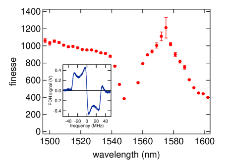
The optical response of a cavity employing a particular grating is obtained by sweeping the laser frequency over a cavity resonance while monitoring the cavity transmission and reflection. Fig. 2 shows the finesse measured over a wavelength range of 1500 nm to 1600 nm, where the cavity FWHM is obtained from Lorentzian fits to the transmission. The inset shows the PDH signal at a wavelength of 1560 nm; the width (peak - valley) of the steep central section is approximately equal to . The finesse varies substantially, with maxima at 1500 nm () and 1575 nm (). The finesse of a low-loss cavity is related to the mirror reflectivities by Siegman (1986)
| (1) |
where describes all other round-trip losses, such as absorption, scattering, and diffraction. A lower bound for the reflection is thus provided by
| (2) |
and yields a value of at 1575 nm. Variations in the reflectivity with wavelength are predicted with RCWA calculations Mateus et al. (2004); Germer (mech), and we will employ such data in future sample designs. Even at a wavelength of 1548 nm, where the finesse takes its minimum value of , the reflectivity is . By comparison, a quarter-wave stack employing conventional dielectrics would need 16 - 34 dielectric layers to achieve a reflectivity of , would be 7 - 10 times thicker, and have 16 - 31 times the mass per unit area.
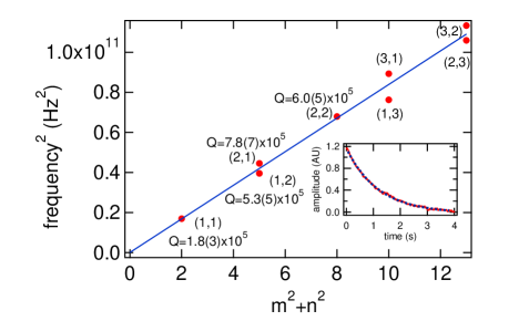
We next describe the mechanical characteristics of the grating reflectors. To this end, we lock a laser with a wavelength of 1560 nm to the cavity with a bandwidth of approximately 12 kHz by means of the PDH signal shown in Fig. 2. Analysis of the rapid (12 kHz) variations in the PDH signal by means of an rf spectrum analyzer reveals hundreds of well-resolved spectral lines in the frequency range of 130 kHz to several MHz. The normal mode frequencies of a uniform square membrane of side , tensile stress , and density are given by Timoshenko (1937)
| (3) |
where and are positive integers. Fig. 3 shows an identification of the eight lowest-frequency modes according to eqn. (3). Clearly the degeneracy of modes with the same sum is broken, a fact readily attributable to the asymmetric stress imposed by patterning the membranes with gratings (Fig. 1b). The amplitude of the response is found to decrease substantially at frequencies above 3 MHz; this is easily understood, as the distance between antinodes Timoshenko (1937) of the mode is then smaller than the size of the optical spot on the grating.
An interesting question that arises is whether the motion of individual fingers in the grating can be observed as well. In the present sample, the frequency of the fundamental finger mode is MHz, at which point the density of membrane modes is very high (mean spacing between modes 3 kHz). Thus, even if the motion of a finger were transduced by the cavity, the response would not be distinguishable from that of a membrane mode. The situation is vastly more favorable for a smaller membrane. In a square membrane with and finger length , for example, the fundamental mode of a finger would fall midway between the (1,1) and (1,2) modes of the membrane, and thus would be easily identified.
The rf spectrum analyzer does not have the resolution necessary to measure the intrinsic linewidths of the individual mechanical modes, so for this purpose we turn to a time-domain approach. The membrane is driven to oscillate at one of its natural frequencies by means of radiation pressure from an intensity-modulated auxiliary laser, and after extinguishing the excitation, the mechanical ringdown is measured with a resonant PDH probe. In this case, the PDH response is demodulated at the mechanical frequency with a lockin amplifier, and the oscillation amplitude is recorded as a function of time. A typical ringdown measurement, taken on the (2,1) mode with a frequency of 211 kHz, is shown in the inset to Fig. 3. The decay is exponential with a time constant of s, corresponding to a mechanical quality factor of . We have measured in this way the mechanical quality factors of the first four modes, which are given in Fig. 3 and range from to .
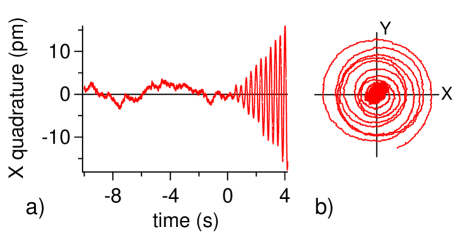
Finally, we illustrate qualitatively the case of self-induced oscillation when the light injected into the cavity is detuned to the high-frequency (“blue”) side of the cavity resonance. By locking the laser to the cavity with a DC offset in the PDH signal we force a detuning of while maintaining an approximately linear response of the signal to the cavity length. The PDH signal is demodulated at a frequency of 211 kHz corresponding to the (2,1) mode. Fig. 4a shows one quadrature of the demodulated signal where the laser is initially tuned to resonance with the optical cavity, and then abruptly detuned to the blue at . The signal for reflects thermal motion, and a detailed analysis confirms motion with a fluctuating amplitude given by Boltzmann statistics. In the phasor representation of both demodulated quadratures shown in Fig. 4b, the transition between thermal motion with a fluctuating phase and a well-defined oscillatory behavior is clearly seen, and the fact that the demodulated phase evolves with time (spiral behavior) is evidence of an optically-induced modification of the oscillation frequency Kippenberg and Vahala (2007).
We have demonstrated a micromechanical grating reflector with a reflectivity as high as 99.4%, a mechanical quality factor two orders of magnitude higher than that of mirrors made from conventional quarter-wave stacks, and a mass per unit area more than an order of magnitude lower. Fine-tuning the grating parameters and improving the fabrication process for less surface roughness should allow us to build devices with even higher reflectivity. The mass can be further reduced by using substantially thinner membranes, although calculations show that they will be more sensitive to variations in fabrication. By working with high-stress silicon nitride we expect to be able to significantly increase the mechanical as well Wilson et al. (2009).
We are currently studying how the cavity finesse depends upon the optical spot size on the grating reflector. This is a matter of interest in its own right Kleckner et al. (2010) and may be crucial to substantially increasing the finesse. Preliminary finite difference time-domain calculations suggest that a finesse of is realistic. We are also making a number of refinements in our experimental apparatus aimed at optical cooling, and to this end we soon plan to fabricate membranes containing only a single grating structure. Such a membrane with sides of m would have a mass of kg, 130 times lower than the membrane studied here, mode frequencies 11 times higher, and, as noted earlier, the response of individual fingers within each grating would be easily distinguished from the membrane modes. Finally, in addition to their utility in conventional Fabry-Perot cavities, such highly reflective membranes should be of considerable interest in “membrane in a cavity” experiments as well Thompson et al. (2008); Wilson et al. (2009), which to date have employed membranes with reflectivities below 20%.
We acknowledge National Science Foundation support through the Physics Frontier Center at the Joint Quantum Institute. Research performed in part at the NIST Center for Nanoscale Science and Technology.
References
- Tittonen et al. (1999) I. Tittonen, G. Breitenbach, T. Kalkbrenner, T. Müller, R. Conradt, S. Schiller, E. Steinsland, N. Blanc, and N. F. de Rooij, Physical Review A 59, 1038 (1999).
- Bose et al. (1997) S. Bose, K. Jacobs, and P. L. Knight, Physical Review A 56, 4175 (1997).
- Marshall et al. (2003) W. Marshall, C. Simon, R. Penrose, and D. Bouwmeester, Physical Review Letters 91, 130401 (2003).
- Arcizet et al. (2006) O. Arcizet, P.-F. Cohadon, T. Briant, M. Pinard, A. Heidmann, J.-M. Mackowski, C. Michel, L. Pinard, O. Français, and L. Rousseau, Physical Review Letters 97, 133601 (2006).
- Thompson et al. (2008) J. Thompson, B. Zwickl, A. Jayich, F. Marquardt, S. Girvin, and J. Harris, Nature 452, 72 (2008).
- Wilson et al. (2009) D. Wilson, C. Regal, S. Papp, and H. Kimble, Phys. Rev. Lett. 103, 207204 (2009).
- Gr oblacher et al. (2009) S. Gr oblacher, J. Hertzberg, M. Vanner, G. Cole, S. Gigan, K. Schwab, and M. Aspelmeyer, Nature Physics 5, 485 (2009).
- Kippenberg and Vahala (2007) T. J. Kippenberg and K. J. Vahala, Optics Express 15, 17172 (2007).
- Kleckner et al. (2010) D. Kleckner, W. Irvine, S. Oemrawsingh, and D. Bouwmeester, Physical Review A (2010).
- B ohm et al. (2006) H. R. B ohm, S. Gigan, F. Blaser, A. Zeilinger, M. Aspelmeyer, G. Langer, D. B auerle, J. Hertzberg, and K. Schwab, Applied Physics Letters 89, 223101 (2006).
- Cole et al. (2008) G. D. Cole, S. Gr oblacher, K. Gugler, S. Gigan, and M. Aspelmeyer, Applied Physics Letters 92, 261108 (2008).
- Gr oblacher et al. (2008) S. Gr oblacher, S. Gigan, B. H.R., A. Zeilinger, and M. Aspelmeyer, Europhysics Letters 81, 54003 (2008).
- Kleckner and Bouwmeester (2006) D. Kleckner and D. Bouwmeester, Nature 444, 75 (2006).
- Magnusson and Wang (1992) R. Magnusson and S. S. Wang, Appl. Phys. Lett. 61, 1022 (1992).
- Sharon et al. (1997) A. Sharon, D. Rosenblatt, and A. A. Friesem, Journal of the Optical Society of America A 14, 2985 (1997).
- Fan and Joannopoulos (2002) S. Fan and J. D. Joannopoulos, Physical Review B 65, 235112 (2002).
- Mateus et al. (2004) C. F. R. Mateus, M. C. Y. Huang, Y. Deng, A. R. Neureuther, and C. J. Chang-Hasnain, IEEE Photonics Technology Letters 16, 518 (2004).
- Lalanne et al. (2006) P. Lalanne, J. P. Hugonin, and P. Chavel, Journal of Lightwave Technology 24, 2442 (2006).
- Chang-Hasnain (2011) C. J. Chang-Hasnain, Semiconductor Science and Technology 26, 014043 (2011).
- Huang et al. (2007) M. Huang, Y. Zhou, and C. Chang-Hasnain, Nature Photonics 1, 119 (2007).
- Brückner et al. (2010) F. Brückner, D. Friedrich, T. Clausnitzer, M. Britzger, O. Burmeister, K. Danzmann, E.-B. Kley, A. Tünnermann, and R. Schnabel, Phys. Rev. Lett. 104, 163903 (2010).
- Moharam and Gaylord (1981) M. G. Moharam and T. K. Gaylord, Journal of the Optical Society of America 71, 811 (1981).
- Germer (mech) T. Germer, “Mist: Modeled integrated scatter tool, version 3.01,” (available at http://pml.nist.gov/scatmech).
- Kogelnik and Li (1966) H. Kogelnik and T. Li, Proceedings of the IEEE 54, 1312 (1966).
- Siegman (1986) A. Siegman, Lasers (University Science Books, 1986) Chap. 11.
- Timoshenko (1937) S. Timoshenko, Vibration Problems in Engineering (D. Van Nostrand Company, 1937) Chap. 6.