Spinmotive Force due to Intrinsic Energy of Ferromagnetic Nanowires
Abstract
We study, both analytically and numerically, a spinmotive force arising from inherent magnetic energy of a domain wall in a wedged ferromagnetic nanowire. In a spatially-nonuniform nanowire, domain walls are subjected to an effective magnetic field, resulting in spontaneous motion of the walls. The spinmotive force mechanism converts the ferromagnetic exchange and demagnetizing energy of the nanowire into the electrical energy of the conduction electrons through the domain wall motion. The calculations show that this spinmotive force can be several microvolts, which is easily detectable by experiments.
Recently, an electromotive force of spin origin has been theoretically predictedbarnes1 and experimentally observedyang ; tanaka . This “spinmotive force” reflects the energy conversion of magnetic energy of a ferromagnet into electric energy of conduction electrons via the spin exchange interaction. This offers a new functionality for future spintronic devices. Theoretically, it has been pointed out that the spinmotive force is produced by the spin electric field acting on conduction electronsvolovik ; sanvito ; duine ; tser ; yuta :
| (1) |
where is the unit vector paralell to the direction of the local magnetization in a ferromagnet, the spin polarization of the conduction electrons, and the elementaly charge. It is requied that the magnetization depends both on time and space. To demonstrate the spinmotive force, Yang et al. studied a field-induced domain wall (DW) motion in a uniform nanowireyang , in which the moving DW releases its Zeeman energy into conduction electrons through the spinmotive force mechanism. On the other hand, it has been suggested that a DW motion can be induced solely by “shape effect”barnes2 ; ieda . In addition to the Zeeman energy, a DW has a surface-tension-like intrinsic energy due to the ferromagnetic exchange and magnetic anisotropic energy of the magnetization. Thus in a spatially-nonuniform nanowire a DW spontaneously tends to move to narrower regions in order to reduce its intrinsic energy, which is proportinal to the cross-sectional area of the wireieda ; barnes2 . The shape-effect-induced DW motion thereby gives rise to a spinmotive force without any external field, using the inherent energy of the magnetic texture, i.e., the ferromagnetic exchange and anisotropic energybarnes2 . In reality, the DW motion in a spatially-nonuniform nanowire shows highly nonlinear behaviorsieda ; kyoto1 ; kyoto2 ; parkin ; barnes3 , for a quantitative understanding of which numerical methods are of particular importance.
In this paper, we study, both analytically and numerically, the spinmotive force in a wedged magnetic nanowire. The results of the numerical simulations strongly support this concept, and show that this spinmotive force can be large and lasts long enough to be detected in experiments.
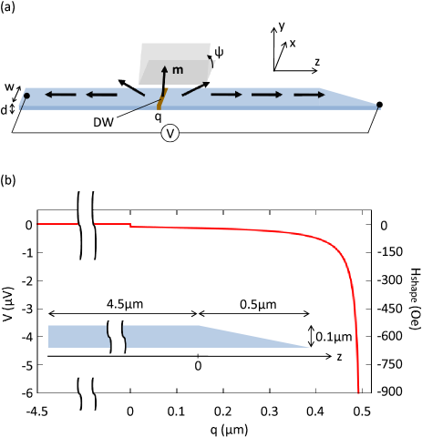
We consider a Permalloy thin wire in which one of its ends is wedged as illustrated in Fig. 1. The length, width, and thickness of the wire are m, nm, and nm, respectively. The cross-sectional area of the wire tapers toward the end as
| (2) |
First, we analyticaly investigate influence of the wedge on the spinmotive force based on a collective-coordinate model. Here we employ the one-dimensional magnetization dynamics along the -axis, assuming uniformity in the lateral direction (the - plane), in which the dynamics of a DW is characterized by two collective coordinates, i.e., the center position and the tilt angle of the DW plane relative to the - plane as indicated in Fig. 1 (a). The time evolution of () is described by the reduced Landau-Lifshiz-Gilbert equationsieda
| (3) | |||||
| (4) |
where is the gyromagnetic ratio, is the Gilbert damping constant, is the wall width parameter, is an external magnetic field, and is a perpendicular anisotropy field due to the demagnetizing interaction. Here and hereafter, upper (lower) sign corresponds to the tail-to-tail (head-to-head) configuration of the DW. In a spatially-nonuniform nanowire, in addition to , DWs are subjected to the “shape-effect” fieldbarnes2 ; ieda :
| (5) |
where is surface tension energy of a DW and is the saturation magnetization. As in the text booktext , energy minimization gives . Here with the exchange stiffness constant, the uniaxial anisotropy constant, and is the ratio of to the perpendicular anisotropy constant. This illustrates that the gradient of the intrinsic DW energy exerts a force acting on the DW. In the present system, the magnetic anisotropy comes from the demagnetizing field while the crystalline magnetic anisotropy is negligible. It is the exchange and the demagnetizing interaction between the magnetization that is responsible for .
From Eqs. (3) and (4), in a spatially-nonuniform magnetic nanowire, can drive a DW and make precess the DW plane even without the external field . In the light of this simplification, with some sign convention the spinmotive force across the DW is obtained as
| (6) |
Equation (6) indicates that the sign of the spinmotive force reflects that of the precession rate of the DW plane , and is independent of the translational motion of the DWbarnes1 ; yang . When is smaller than the Walker breakdown field , the Larmor torque due to cannot overcome the countertorque due to the perpendicular anisotropy; in Eq. (4) are canceled out by the third term with a certain , resulting in . In contrast, if is larger than , the DW plane precesses with finite . Thus, the spinmotive force appears only when is above the Walker breakdown field. Once the DW configuration is fixed, the sign of the spinmotive force is determined by the direction of .
The shape-effect field and the spinmotive force , calculated from Eqs. (2), (4), (5) and (6), with and the tail-to-tail configuration, as a function of the DW position are shown in Fig. 1 (b). Typical values for a Permalloy nanowire are employed; Hz/T, , T, J/m, J/m3, and . We neglect the third term in Eq. (4), in which is tens of Oersted for the Permalloy nanowire, and is assumed. In this scheme is proportional to , and in the wedged part () the finite spinmotive force appears. Figure 1 (b) indicates that the spinmotive force of several microvolts can be obtained in the present system without any applied field but using the intrinsic magnetic energy of the nanowire.
The collective-coordinate model imposes a number of assumptions, i.e., the uniformity in the - plane , a rigid wall structure, and constant magnetic shape anisotropies. In fact, these assumptions are no longer guaranteed without check for nanowires with the shape modulation and in particular for relatively higher driving field region (). To confirm the above prediction and to obtain the detailed real-time spectrum of the induced spinmotive force with high accuracy, here we perform numerical calculations free from the constraint. We solve the original Landau-Lifshiz-Gilbert equation
| (7) |
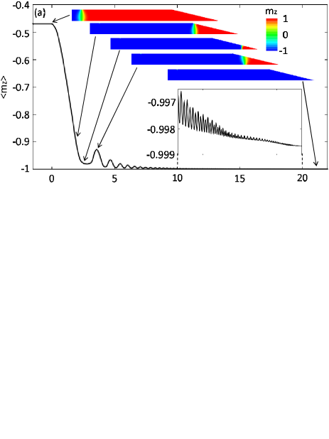
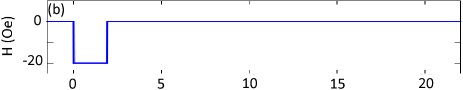
using the OOMMF codeoommf with dividing the sample into nm3 cells. Here is the effective magnetic field including the external, exchange and demagnetizing fields. The parameters are the same as used in the one-dimensional calculation. Here the demagnetizing field is taken into account by the dipole interaction, instead of . To track the DW position we calculate the time evolution of spatially-averaged value of the -component of the magnetization, , as shown in Fig. 2 (a). Initially (), a transverse tail-to-tail DW is trapped at m, where the nm3 defect is introduced. From to ns a constant magnetic field pulse , where Oe, is applied, see Fig. 2 (b); during this period, the DW has been dislodged from the defect, traveled about 1 m and entered the wedged part. The DW maintains its transverse structure through the field-induced motion. Even after the applied field is turned off at ns, the DW keeps moving forward and slides down the slope with the help of the shape-effect. In this stage there arises an oscillation of the DW position, i.e. the back and forth motion of the DW, with the periodic nucleation and annihilation of antivortices. This is because of the Walker breakdown induced by the shape-effect. In the one-dimensional model, as the tilt angle develops through the Walker breakdown motion, in Eq. (3) oscillates and thus can be negative. This oscillatory motion continues until the DW reaches the end of the nanowire and disappears at ns. We remark here that after the whole event, the exchange and the demagnetizing energy of the nanowire has obviously decreased. The spinmotive force mechanism, which guarantees the total energy conservation, dictates that the decreased magnetic energy is received by the conduction electrons, resulting in an electromotive force.
 |
 |
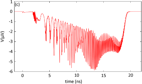 |
A measurable voltage between given two points can be calculated as the spatial difference of the spin-independent electric potential between the points, which is obtained by solving the Poisson equation yang ; ohe . Figure 2 (c) shows the spinmotive force between the ends of the nanowire [see Fig. 1 (a)] versus time. In spite of the field-induced DW motion, from to ns, a very small spinmotive force is observed since Oe is below the Walker breakdown field for the present nanowire. After the system goes into the Walker breakdown, with no applied magnetic field, the finite spinmotive force is induced until the DW vanishes at ns. The observed spinmotive force is of the order of microvolts, oscillating but unipolar. These facts agree with the analytical prediction from Eq. (6). The oscillation of the spinmotive force reflects the DW structure transformation. Apparently becomes larger in an anti-vortex motion than in that of a transeverse wall and so does . The peaks of the spinmotive force signal in Fig. 2 (c) are associated with the traverse motion of an antivortex, i.e., the plateau in the DW position curve in Fig. 2 (a). The DW moves back and forth with changing its structure, whereas, the sign of the spinmotive force is unchanged and determined by the direction of the shape-effect magnetic field as estimated in Fig. 1 (b) [see also the discussion below Eq. (6)].
In conclusion, we have investigated the spinmotive force in a wedged magnetic nanowire, and numerically confirmed the spinmotive force of several microvolts for tens of nano seconds, using only the inherent magnetic energy of the nanowire. The behavior of the spinmotive force depends on the shape and the material nature of the sample, which implies the posibility of various applications.
Acknowledgements.
We are grateful to M. Hayashi and S. Mitani in National Institute for Material Science for helpful comments on this work. This research was suported by Giant-in-Aid for Science Research from MEXT, Japan, and the Next Generation Supercomputer Project, Nanoscience Program from MEXT, Japan.References
- (1) S. E. Barnes and S. Maekawa: Phys. Rev. Lett. 98 (2007) 246601.
- (2) S. A. Yang, G. S. D. Beach, C. Knutson, D. Xiao, Z. Zhang, M. Tsoi, Q. Niu, A. H. MacDonald, and J. L. Erskine: Phys. Rev. B 82 (2010) 054410.
- (3) P. N. Hai, S. Ohya, M. Tanaka, S. E. Barnes, and S. Maekawa: Nature 458 (2009) 489.
- (4) G. E. Volovik: J. Phys. C 20 (1987) L83.
- (5) M. Stamenova, T. Todorov, and S. Sanvito: Phys. Rev. B 77 (2008) 054439.
- (6) R. A. Duine: Phys. Rev. B 77 (2008) 014409.
- (7) Y. Tserkovnyak and M. Mecklenburg: Phys. Rev. B 77 (2008) 134407.
- (8) Y. Yamane, J. Ieda, J. Ohe, S. E. Barnes, S. Maekawa: J. Appl. Phys. (2011) 07C735.
- (9) S. E. Barnes, J. Ieda, and S. Maekawa: Appl. Phys. Lett. 89 (2006) 122507.
- (10) J. Ieda, H. Sugishita, and S. Maekawa: J. Magn. Magn. Mat. 322 (2010) 1363.
- (11) A. Yamaguchi, T. Ono, S. Nasu, K. Miyake, K. Mibu, and T. Shinjo: Phys. Rev. Lett. 92 (2004) 77205.
- (12) A. Himeno, K. Kondo, H. Tanigawa, S. Kasai, and T. Ono: J. Appl. Phys. 103 (2008) 07E703.
- (13) S. S. P. Parkin, M. Hayashi, and L. Thomas: Science 320 (2008) 190.
- (14) V. Lecomte, S. E. Barnes, J. P. Eckmann, and T. Giamarchi: Phys. Rev. B 80 (2009) 054413.
- (15) A. P. Malozemoff and J. C. Slonczewski: Magnetic Domain Walls in Bubble Materials (Academic Press, New York, 1979) Chap. 5, 7, and 10.
- (16) http://math.nist.gov/oommf/
- (17) J. Ohe and S. Maekawa: J. Appl. Phys. 105 (2009) 07C706.