Enhanced Transmission in Rolled-up Hyperlenses utilizing Fabry-Peŕot Resonances
Abstract
We experimentally demonstrate that the transmission though rolled-up metal/semiconductor hyperlenses can be enhanced at desired frequencies utilizing Fabry-Pérot resonances. By means of finite difference time domain simulations we prove that hyperlensing occurs at frequencies of high transmission.
Metamaterials offer the possibility to tailor their effective optical parameters Pendry et al. (1999); Smith et al. (2000) allowing e.g. sub-wavelength imaging. Beside metamaterials with negative index of refraction Veselago (1968); Pendry (000a); Fang et al. (2005), metamaterials consisting of alternating layers of metal and dielectric Ramakrishna et al. (2003); Wood, Pendry, and Tsai (2006) are able to transmit electromagnetic waves containing sub-wavelength details of an object. In the latter case sub-wavelength imaging relies on the anisotropic permittivity of the multilayer structure leading to unidirectional propagation of electromagnetic waves. Magnification of a sub-wavelength object can be achieved if the multilayers are curved Jacob, Alekseyev, and Narimanov (2006). As a consequence the light is channeled in radial direction. These so called hyperlenses have been fabricated consisting of multilayers of Ag and oxides with an effective plasma frequency in the violet and ultraviolet regime Liu et al. (2007); Rho et al. (2010). They are most efficient close to the effective plasma frequency in the longitudinal component of the permittivity of the metamaterial Ramakrishna et al. (2003), which can be tuned by the ratio of the thicknesses of the dielectric and metal layer. Recently we have shown that using the concept of self-rolling strained layers Prinz et al. (2000); Schmidt and Eberl (2001); Schumacher et al. (2005); Mendach et al. (2005), one can fabricate a rolled-up metal/semiconductor microtube which exhibits optical anisotropy and acts as a hyperlens Schwaiger et al. (2009). The operation frequency of these rolled-up hyperlenses (RHLs) is tunable in the visible and near-infrared regime.
In this letter we propose a concept to optimize the transmission through a metamaterial. We utilize Fabry-Pérot resonances related to the total thickness of the metamaterial to obtain increased transmission in a desired frequency regime. We illustrate this concept for the example of a RHL Schwaiger et al. (2009, 2011); Smith et al. (2009, 2010) consisting of alternating layers of Ag and semiconductor as sketched in Fig. 1(a). We show that the number of rotations of our RHL can be used to maximize the transmission at their operation frequency and obtain values as high as 52. Finite difference time domain (FDTD) simulations prove the hyperlensing ability of the presented structures.
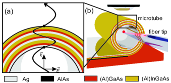
The preparation of the RHLs is described in the following: Initially a semiconductor heterostructure is grown on a GaAs substrate using molecular beam epitaxy. The heterostructure consists of a GaAs buffer layer ( nm), an AlAs sacrificial layer ( nm) followed by a strained Al20In13Ga67As layer ( nm), a strained In16Ga84As layer ( nm), and an unstrained Al23Ga77As layer ( nm). On top of these semiconductors an Ag layer is deposited by thermal evaporation. Finally the AlAs sacrificial layer is removed by selective etching and the AlInGaAs/InGaAs/AlGaAs/Ag system minimizes its strain energy by rolling up into a RHL with several rotations.
To perform transmission measurements through the RHLs we use a fiber based transmission measurement setup which is sketched in Fig. 1(b). A tapered single mode fiber with a tip diameter of m can be manipulated into the microtubes with the help of an XYZ piezo stage. Monochromatic light, which is coupled into the optical fiber is guided to a hole in the sidewall near the tip and emitted perpendicularly to the fiber axis. After being transmitted through the wall of the microtube the light is collected with a near-infrared corrected objective, and detected by an InGaAs photodiode using lock-in technique. For normalization of the spectra we acquire spectra with the fiber tip inside the microtube and spectra with the tip outside the microtube.
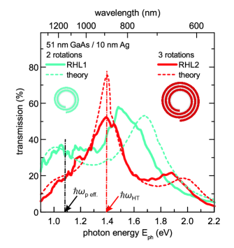
In Fig. 2 we compare the transmission through two exemplary hyperlenses RHL1 and RHL2 with identical operation frequency, i.e. identical individual layer thicknesses (nm) and (AlIn)GaAs (nm), but varying number of rotations. RHL1 exhibits a total thickness of nm, while RHL2 exhibits a total thickness of nm. In the range from eV to eV the transmission through RHL2 exceeds that one through RHL1 even though the total wall thickness is increased, i.e. . The maximum transmission through RHL1 occurs at eV with a value of . In the case of the RHL2 the maximum transmission occurs at eV with a value of .
To model the measurements we calculate the transmission using the transfer matrix method Born and Wolf (1980) and approximate the RHL as a flat superlattice of Ag and GaAs. The dielectric functions of Ag and GaAs were taken from Ref. Palik (1985). The calculated transmission curves for the fabricated RHLs are presented in Fig. 2 (dashed lines). They show a good agreement with the measured data. To understand the origin of the transmission maxima we perform further calculations. We vary the single layer thicknesses of Ag and GaAs while keeping the layer thickness ratio constant. This allows us to vary the total thickness of the RHL while maintaining the effective optical properties and the effective plasma frequency . We find that the maximum occurring in the calculations on RHL2 can be shifted to lower photon energies with increasing total thickness of the RHL. Furthermore, we double and triple the total thickness (nm and nm) and determine a transmission maximum at the same energetical position eV. This clearly shows that the observed transmission maximum is a Fabry-Pérot resonance related to the total thickness of the RHL.
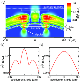
In order to obtain hyperlensing, the operation frequency of the RHL has to be in the vicinity of the plasma frequency of the effective medium Schwaiger et al. (2009) which is marked in Fig. 2 with a black arrow. On the other hand the transmission through any metallic material drops below the plasma frequency. A compromise of high transmission and hyperlensing operation quality has to be found in the case of hyperlensing devices. In the following we use FDTD to show that RHL2 exhibits pronounced hyperlensing not only directly at the plasma frequency but also at a nearby Fabry-Pérot maximum at (Fig. 2 red arrow) where the transmission is increased to . We simulate the transmission through RHL2 using the same optical parameters as in the transfer matrix calculations in Fig 2 and the inner radius corresponding to RHL2 (m).
We place two dipoles at a distance of nm from the inner surface of RHL2. Both emit at an energy of eV which corresponds to the maximum transmission of calculations on RHL2. The magnetic field vector was chosen to point along the rolling axis of RHL2 and the electric field vector perpendicular to it. In Fig. 3(a) we show the intensity of magnetic field in a color plot. We observe that the field is radially channeled which indicates that the structure exhibits an unidirectional propagation of electromagnetic waves. As a consequence, the fields of the two dipoles can be clearly resolved at the outer perimeter. This is also demonstrated in Fig. 3(b) and (c) where we collected the intensity of the magnetic field in a distance of m from the dipoles, with (Fig. 3(b)) and without (Fig. 3(c)) RHL2. Without RHL2 between the sources and the monitor the field of the two dipoles have already merged to a Gaussian-shaped intensity distribution. With RHL2 the peak fields of the two dipoles are still distinguishable, which demonstrates hyperlensing.
In conclusion we experimentally showed that the transmission through a RHL can be optimized by tuning the Fabry-Pérot resonance related to multiple reflection at the inner and outer surface of the RHL and achieve a transmission value as high as . Furthermore, using FDTD simualtions we demonstrated that hyperlensing is possible at the frequency of high transmission.
We gratefully acknowledge support of the Deutsche Forschungsgemeinschaft via the Graduiertenkolleg 1286 “Functional Metal-Semiconductor Hybrid Systems” and LExI “Nano-Spintronics”.
References
- Pendry et al. (1999) J. B. Pendry, A. J. Holden, D. J. Robbins, and W. J. Stewart, IEEE Trans. Microwave Theory Tech. 47, 2075 (1999).
- Smith et al. (2000) D. R. Smith, W. J. Padilla, D. C. Vier, S. C. Nemat-Nasser, and S. Schultz, Phys. Rev. Lett. 84, 4184 (2000).
- Veselago (1968) V. G. Veselago, Soviet Physics USPEKHI 10, 509 (1968).
- Pendry (000a) J. B. Pendry, Phys. Rev. Lett. 85, 3966 (2000a).
- Fang et al. (2005) N. Fang, H. Lee, C. Sun, and X. Zhang, Science 308, 534 (2005).
- Ramakrishna et al. (2003) S. A. Ramakrishna, J. B. Pendry, M. C. K. Wiltshire, and W. J. Stewart, J. Mod. Opt. 50, 1419 (2003).
- Wood, Pendry, and Tsai (2006) B. Wood, J. B. Pendry, and D. P. Tsai, Phys. Rev. B 74, 115116 (2006).
- Jacob, Alekseyev, and Narimanov (2006) Z. Jacob, L. V. Alekseyev, and E. Narimanov, Opt. Expr. 14, 8247 (2006).
- Liu et al. (2007) Z. Liu, H. Lee, Y. Xiong, C. Sun, and X. Zhang, Science 315, 1686 (2007).
- Rho et al. (2010) J. Rho, Z. Ye, Y. Xiong, X. Yin, Z. Liu, H. Choi, G. Bartal, and X. Zhang, Nat. Commun. 1, 143 (2010).
- Prinz et al. (2000) V. Y. Prinz, V. A. Seleznev, A. K. Gutakovsky, A. V. Chehovskiy, V. V. Preobrazhenskii, M. A. Putyato, and T. A. Gavrilova, Physica E 6, 828 (2000).
- Schmidt and Eberl (2001) O. G. Schmidt and K. Eberl, Nature 410, 168 (2001).
- Schumacher et al. (2005) O. Schumacher, S. Mendach, H. Welsch, A. Schramm, C. Heyn, and W. Hansen, Appl. Phys. Lett. 86, 143109 (2005).
- Mendach et al. (2005) S. Mendach, T. Kipp, H. Welsch, C. Heyn, and W. Hansen, Semicond. Sci. Technol. 20, 402 (2005).
- Schwaiger et al. (2009) S. Schwaiger, M. Bröll, A. Krohn, A. Stemmann, C. Heyn, Y. Stark, D. Stickler, D. Heitmann, and S. Mendach, Phys. Rev. Lett. 102, 163903 (2009).
- Schwaiger et al. (2011) S. Schwaiger, M. Klingbeil, J. Kerbst, A. Rottler, R. Costa, A. Koitmäe, M. Bröll, C. Heyn, Y. Stark, D. Heitmann, and S. Mendach, arXiv:1104.2208v1 (2011).
- Smith et al. (2009) E. J. Smith, Z. Liu, Y. F. Mei, and O. G. Schmidt, Appl. Phys. Lett. 95, 083104 (2009).
- Smith et al. (2010) E. J. Smith, Z. Liu, Y. F. Mei, and O. G. Schmidt, Appl. Phys. Lett. 96, 019902 (2010).
- Born and Wolf (1980) M. Born and E. Wolf, Principles of Optics (Pergamon Press, Oxford, 1980).
- Palik (1985) E. D. Palik, Handbook of Optical Constants of Solids (Academic Press, 1985).