Minimization of the Switching Time of a Synthetic Free Layer in Thermally Assisted Spin Torque Switching
Abstract
We theoretically studied the thermally assisted spin torque switching of a synthetic free layer and showed that the switching time is minimized if the condition is satisfied, where , , and are the coupling field of two ferromagnetic layers, the amplitude of the spin torque, and the Gilbert damping constant, respectively. We also showed that the coupling field of the synthetic free layer can be determined from the resonance frequencies of the spin-torque diode effect.
Spin random access memory (Spin RAM) using the tunneling magnetoresistance (TMR) effect [1, 2] and spin torque switching [3, 4] is one of the important spin-electronics devices for future nanotechnology. For Spin RAM application, it is highly desired to realize the magnetic tunnel junction (MTJ) with high thermal stability , a low spin-torque switching current , and a fast switching time. Recently, large thermal stabilities have been observed in anti-ferromagnetically [5] and ferromagnetically [6] coupled synthetic free (SyF) layers in MgO-based MTJs. In particular, the ferromagnetically coupled SyF layer is a remarkable structure because it shows thermal stability of more than 100 with a low switching current [6].
Since the coupling between the ferromagnetic layers in the SyF layer is indirect exchange coupling, we can systematically vary the sign and strength of the coupling field by changing the spacer thickness between the two ferromagnetic layers. As shown in ref. [7] , the thermal switching probability of the SyF layer is a double exponential function of the coupling field, and a tiny change in the coupling field can significantly increase or decrease the switching time. Therefore, it is of interest to physical science to study the dependence of the thermal switching time on the coupling field.
In this paper, we theoretically studied the spin-current-induced dynamics of magnetizations in an SyF layer of an MTJ. We found the optimum condition of the coupling field, which minimizes the thermally assisted spin torque switching time. We showed that the coupling field of the two ferromagnetic layers in the SyF layer can be determined by using the spin torque diode effect.
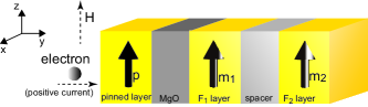
Let us first briefly describe the thermal switching of the SyF layer in the weak coupling limit, , where , , , and are the uniaxial anisotropy energy per unit volume, the coupling energy per unit area, and the volume and cross-sectional area of the single ferromagnetic layer, respectively. For simplicity, we assume that all the material parameters of the two ferromagnetic layers (F1 and F2) in the SyF layer are identical. A typical MTJ with an SyF layer is structured as a pinned layer/MgO barrier/ferromagnetic (F1) layer/nonmagnetic spacer/ferromagnetic (F2) layer (see Fig. 1), where the F1 and F2 layers are ferromagnetically coupled due to the interlayer exchange coupling [6]. The F1 and F2 layers have uniaxial anisotropy along the axis and two energy minima at , where is the unit vector pointing in the direction of the magnetization of the Fk layer. The spin current injected from the pinned layer to the F1 layer exerts spin torque on the magnetization of the F1 layer [8]. Then, the magnetization of the F1 layer switches its direction due to the spin torque, after which the magnetization of the F2 layer switches its direction due to coupling. By increasing the coupling field, the potential height of the F1 (F2) layer for the switching becomes high (low), which makes the switching time of the F1 (F2) layer long (short). Then, a minimum of the total switching time appears at a certain coupling field, as we shall show below.
The switching probability from the parallel (P) to antiparallel (AP) alignment of the pinned and free layer magnetizations is given by [7]
| (1) |
where is the switching rate of the Fk layer. The attempt frequency is given by , where , , and . , , , , , and are the Gilbert damping constant, gyromagnetic ratio, applied field, uniaxial anisotropy field, coupling field, and thermal stability, respectively, and is the ferromagnetic layer thickness. is given by [7, 9]
| (2) |
| (3) |
is the potential height of the F1 layer before the F2 layer switches its magnetization while is the potential height of the F2 layer after the F1 layer switches its magnetization. is the amplitude of the spin torque in the unit of the magnetic field, where is the spin polarization of the current . The positive current corresponds to the electron flow from the pinned to the F1 layer; i.e., the negative current () induces the switching of the F1 layer. The field strengths should satisfy and because eq. (1) is valid in the thermal switching region. In particular, means that . The effect of the field like torque is neglected in Eq. (2) because its magnitude, where the beta term satisfies , is less than 1 Oe in the thermal switching region and thus, negligible.
Figure 2 shows the dependences of the switching times at and on the coupling field with the currents (a) , (b) , and (c) A. The values of the parameters are taken to be , MHz/Oe, Oe, emu/c.c., nm2, nm, and K [6]. The values of and are taken to be Oe and , respectively. The value of is chosen so as to make the potential heights for the switching low as much as possible ( and ). As shown in Fig. 2, the switching time is minimized at a certain coupling field. We call this as the optimum coupling field for the fast thermally assisted spin torque switching.
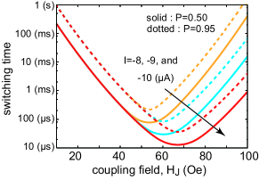
Let us estimate the optimum coupling field. For a small , the switching time of the F2 layer is the main determinant of the total switching time; thus, eq. (1) can be approximated as . By increasing , increases and the switching time () decreases. Fast switching is achieved for in this region. On the other hand, for a large , the switching time of the F1 layer dominates, and eq. (1) is approximated as . The switching time () decreases with decreasing . Fast switching in this region is also achieved for . The switching rate is mainly determined by . By putting , the optimum coupling field is obtained as
| (4) |
This is the main result of this paper. The values obtained with eq. (4) for and A are 53.7, 60.5, and 67.2 Oe, respectively, which show good agreement with Fig. 2.
The condition means that the most efficient switching can be realized when two switching processes of the F1 and F2 layers occur with the same rate. means that the magnetization of the F1 layer can easily switch due to a large spin torque. However, the system should stay in this state for a long time because of a small switching rate of the F2 layer. On the other hand, when , it takes a long time to switch the magnetization of the F1 layer. Thus, when and are different, the system stays in an unswitched state of the F1 or F2 layer for a long time, and the total switching time becomes long. For thermally assisted field switching, we cannot find the optimum condition of the switching time because the switching probabilities of the F1 and F2 layers are the same. Factor 2 in eq. (4) arises from the fact that affects the switchings of both the F1 and F2 layers, while assists that of only the F1 layer. When , the total switching time is independent of the current strength, because the total switching time in this region is mainly determined by the switching time of the F2 layer, which is independent of the current. In the strong coupling limit, , two magnetizations switch simultaneously [7], and the switching time is independent of the coupling field.
For the AP-to-P switching, the factors and are given by , , , and . In this case, a positive current () induces the switching. By setting , the optimum coupling field is obtained as . Thus, for both P-to-AP and AP-to-P switchings, the optimum coupling field is expressed as .
In the case of the anti-ferromagnetically coupled SyF layer, and in eqs. (2) and (3) should be replaced by and , respectively, where the sign of the coupling field is negative (). The optimum condition is given by , where the negative current is assumed to enhance the switching of the F1 layer. For a sufficiently large positive field , this condition cannot be satisfied because is always smaller than .
One might notice that the condition for the ferromagnetically coupled SyF layer has another solution , which is independent of the coupling field. We exclude this solution because such and cannot satisfy the conditions for the thermal switching regions and simultaneously. Similarly, for the anti-ferromagnetically coupled SyF layer, we exclude the solution obtained from .
The natural question from the above discussion is how large the coupling field is. The coupling field of a large plane film can be determined from two ferromagnetic resonance (FMR) frequencies [10, 11] corresponding to the acoustic and optical modes, which depend on . The antiferromagnetic coupling field can also be determined by the magnetization curve [5], in which finite magnetization appears when the applied field exceeds the saturation field . These methods are, however, not applicable to nanostructured ferromagnets such as the Spin RAM cells because the signal intensity is proportional to the volume of the ferromagnet, and thus, the intensity from the Spin RAM cell is negligibly small. It is desirable to measure the coupling field of each cell because strongly depends on the surface state and may differ significantly among the cells obtained from a single film plane.
Here, we propose that the coupling field can be determined by using the spin torque diode effect [12, 13, 14] of the SyF layer. This method is applicable to a nanostructured ferromagnet, although the basic idea is similar to that of FMR measurement.
The spin torque diode effect is measured by applying an alternating current to an MTJ, which induces oscillating spin torque on the magnetization of the F1 layer. The free layer magnetizations oscillate due to the oscillating spin torque and the coupling, which lead to the oscillation of the TMR and the d.c. voltage . Here, , and and correspond to the resistances at the parallel and antiparallel alignments of and , respectively. is the unit vector pointing in the direction of the pinned layer magnetization. is given by
| (5) |
where . The SyF layer shows large peaks of d.c. voltage at the FMR frequencies of the acoustic and optical modes. The coupling field can be determined from these frequencies.
The resonance frequency of the ferromagnetically coupled system is obtained as follows. The free energy of the SyF layer is given by
| (6) |
where the first, second, third, and fourth terms are the Zeeman energy, uniaxial anisotropy energy, demagnetization field energy, and coupling energy, respectively. The and axes are normal to the plane and parallel to the easy axis, respectively. The applied field, , lies in the plane with angle from the axis. The equilibrium point is located at , where satisfies . We employ a new coordinate in which the and axes are parallel to the axis and , respectively, and denote a small component of the magnetization around as . The magnetization dynamics is desribed by using the Landau-Lifshitz-Gilbert (LLG) equation , where is the field acting on . By assuming the oscillating solution () of and , keeping the first-order terms of and , and neglecting the damping term, the LLG equations can be linearized as . The nonzero components of the coefficient matrix are , , , and . The FMR resonance frequencies are obtained under the condition , and are given by and , where and . can be determined from these frequencies. For the anti-ferromagnetically coupled system, in equilibrium in general, and the resonance frequencies are obtained by solving the matrix equation.
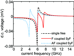
Figure 3 shows the dependences of the d.c. voltage of the single free layer (solid) and the ferromagnetically (dotted) and anti-ferromagnetically (dashed) coupled SyF layers on the applied current frequency calculated by solving the LLG equations of the F1, F2, and pinned layers. The spin torque term, , is added to the LLG equation of the F1 layer. Here the field like torque is taken into account because it affects the shape of significantly [12]. The magnetic field acting on is given by , where is the pinning field due to the bottom anti-ferromagnetic layer [6]. In Fig. 3, mA, , Oe, Oe, kOe, and [12]. The and of the ferromagnetically coupled SyF layer are estimated to be 5.98 and 7.50 GHz, respectively, which show good agreement with the peak points in Fig. 3. These results indicate that the spin torque diode effect is useful in determining the coupling field.
In summary, we theoretically studied the dependence of the thermally assisted spin torque switching time of a SyF layer on the coupling field. We found that the switching time is minimized if the condition of is satisfied. We showed that the coupling field can be determined from the resonance frequency of the spin torque diode effect.
The authors would like to acknowledge H. Kubota, T. Saruya, D. Bang, T. Yorozu, H. Maehara, and S. Yuasa of AIST for their support and the discussions they had with us.
References
- [1] S. Yuasa, T. Nagahama, A. Fukushima, Y. Suzuki, and K. Ando: Nature Materials 3 (2004) 868.
- [2] S. S. P. Parkin, C. Kaiser, A. Panchula, P. M. Rice, B. Hughes, M. Samant, and S. H. Yang: Nature Materials 3 (2004) 862.
- [3] J. C. Slonczewski: Phys. Rev. B 39, 6995 (1989); J. Magn. Magn. Mater. 159 (1996) L1.
- [4] L. Berger: Phys. Rev. B 54 (1996) 9353.
- [5] J. Hayakawa, S. Ikeda, K. Miura, M. Yamanouchi, Y. M. Lee, R. Sasaki, M. Ichimura, K. Ito, T. Kawahara, R. Takemura, T. Meguro, F. Matsukura, H. Takahashi, H. Matsuoka, and H. Ohno: IEEE. Trans. Magn. 44 (2008) 1962.
- [6] S. Yakata, H. Kubota, T. Sugano, T. Seki, K. Yakushiji, A. Fukushima, S. Yuasa, and K. Ando: Appl. Phys. Lett. 95 (2009) 242504.
- [7] T. Taniguchi and H. Imamura: Phys. Rev. B 83 (2011) 054432.
- [8] Private communication with Hitoshi Kubota. It was experimentally shown that the critical current in the CoFeB/Ru/CoFeB spin valve is one order of magnitude larger than that in CoFeB/MgO/CoFB MTJs (unpublished). This result means that the spin torque arising between the free layers is negligible compared with that arising from the spin current injected from the pinned layer.
- [9] In ref. [7] , is expressed as , which is equivalent to eq. (2).
- [10] Z. Zhang, L. Zhou, and P. E. Wigen: Phys. Rev. B 50 (1994) 6094.
- [11] J. Lindner, U. Wiedwald, K. Baberschke, and M. Farle: J. Vac. Sci. Technol. A 23 (2005) 796.
- [12] A. A. Tulapurkar, Y. Suzuki, A. Fukushima, H. Kubota, H. Maehara, K. Tsunekawa, D. D. Djayaprawira, N. Watanabe, and S. Yuasa: Nature 438 (2005) 339.
- [13] H. Kubota, A. Fukushima, K. Yakushiji, T. Nagahama, S. Yuasa, K. Ando, H. Maehara, Y. Nagamine, K. Tsunekawa, D. D. Djayaprawira, N. Watanabe, and Y. Suzuki: Nature Physics 4 (2008) 37.
- [14] J. C. Sankey, Y.-T. Cui, J. Z. Sun, J. C. Slonczewski, R. A. Buhrman, and D. C. Ralph: Nature Physics 4, (2008) 67.