Laser spot position dependent photothermal mode cooling of a micro-cantilever
Abstract
We explore the laser spot position (LSP) dependent photothermal mode cooling of a micro-cantilever in a Fabry-Pérot (FP) cavity. Depending on the LSP along the lever, photothermal coupling to the first two mechanical modes can be either parallel or anti-parallel. This LSP dependent behavior is analyzed theoretically by a simple model, which is in quantitatively agreement with our experimen tal observation. From simulation, the parallel and anti-parallel coupling region is identified along the lever. We conclude that a more efficient mode cooling may be achieved in the parallel coupling region.
pacs:
05.40.Jc,42.50.Wk,85.85.+j,42.65.SfMicro-resonator has become an ideal candidate for exploring quantum phenomena, such as the Heisenberg uncertainty principle and quantum entanglement, at the boundary between classical and quantum realms 1 ; 2 ; 3 . Preparing the micro-resonator close to its ground mechanical state is a crucial step towards observation of such quantum effects at macroscale 4 ; 5 ; 6 . In addition, cooling operation of the micro-resonator also attracts enormous interest in diverse areas of applied science, ranging from ultra-high sensitive measurement 7 ; 8 to quantum information processing 9 . Recently, cooling schemes for the micro-resonator have been intensely studied 10 ; 11 ; 12 ; 13 , among which optomechanical schemes are proposed as one of the most promising strategies to access the macroscopic quantum regime 14 ; 15 ; 16 ; 17 ; 18 ; 19 . As demonstrated in the pioneer works, the brownian vibrational fluctuations of the micro-resonator can be quenched significantly by the actively controlled optical forces of radiation pressure 20 . On the other hand, implemented through the retarded backaction of optical forces, passive optical cooling of the optomechanical resonator also demonstrates the ability of cooling the fundamental mechanical mode close to ground mechanical state 21 ; 22 ; 23 . Further investigations on passive optical cooling scheme show that the direction of photothermal coupling is mechanical mode dependent, which could be either parallel or anti-parallel for different modes 21 ; 24 . Since anti-parallel coupling may excite one mode while cooling the other, cooling operation could be always benefited from the parallel coupling effect. Thus, it raises an important issue in cooling modes simultaneously. Here we study the mechanical mode dependence of photothermal mode cooling at laser spot positions (LSP) along the optomechanical resonator of compliant micro-cantilever in a low fineness FP cavity. Experiments at five different LSPs clearly revealed a LSP dependent behavior of photothermal mode cooling. With the assistance of theoretical analysis, two types of coupling regions, the parallel coupling region (PCR) and anti-parallel coupling region (aPCR), are sketched out along the micro-cantilever according to the relative direction of bolometric backaction. And we demonstrated that simultaneous cooling of the first two mechanical modes can be realized at the PCR. It paves the way for more efficient cooling of an optomechanical resonator to its classical limit.
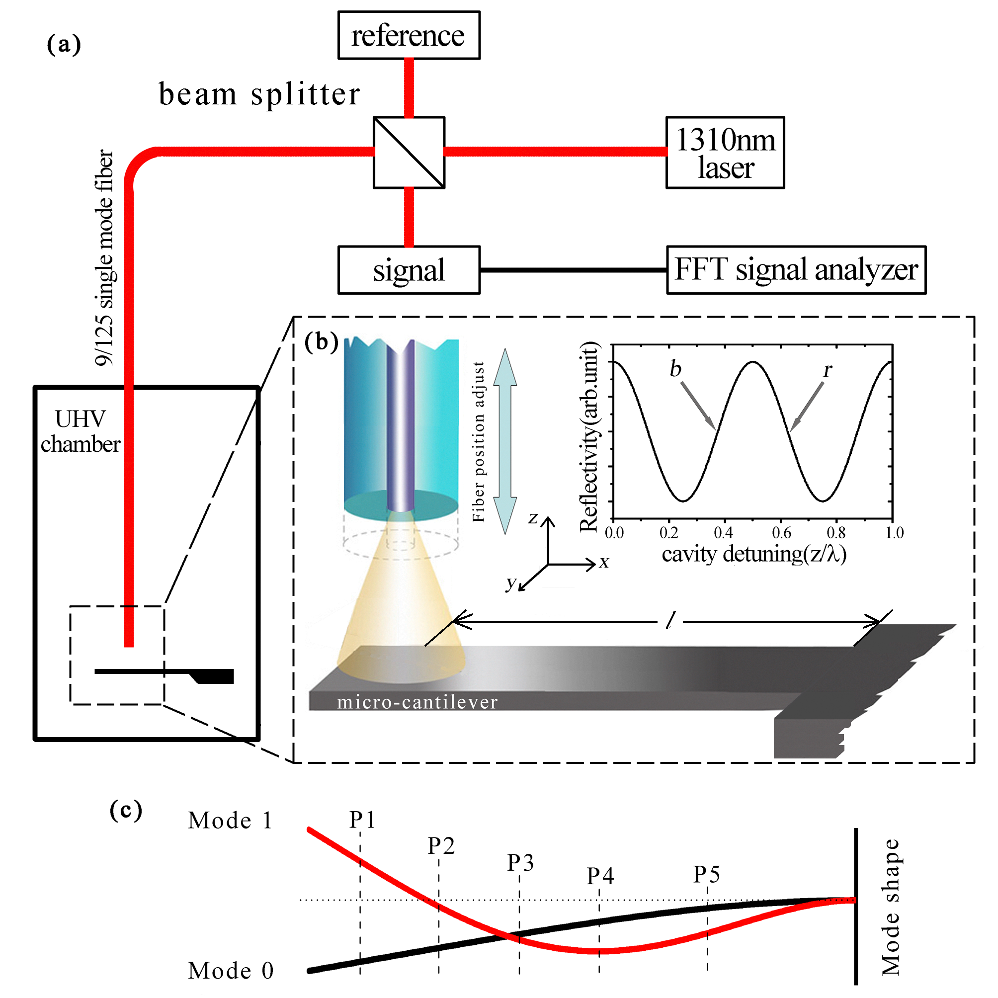
In our experiment, a single crystal silicon micro-cantilever with dimension of 480m10m0.8m is used 25 . And gold film of 80nm thickness is thermally evaporated onto the top side of the lever. The intrinsic resonant frequencies of mode 0 and mode 1 of the micro-cantilever are f0= 4443.4Hz and f1 = 27736.4Hz respectively. In ultra-high vacuum (Torr) and at room temperature, the lever exhibits inherent thermal dissipation with the damping factors =2.9Hz and =15.4Hz for the first two modes. The experimental setup is schematically illustrated in Fig.1. A laser beam of wavelength =1310nm is supplied by a semiconductor diode with power programmable from 10W to 5mW. After split by a 10dB directional optical coupler (reflection = 90%, transmission = 10%), the laser beam is coupled into the ultra-high vacuum system by a single mode optical fiber. Aligning the polished fiber end and the surface of micro-cantilever parallel, a low fineness level-based FP cavity is formed. A fiber stage piezo capable of accurately regulating the fiber position in range of 1m at 300K is employed to switch the working position from the maximum sensitive interference detection point of red detuning r to that of blue detuning b 26 . Laser reflected off the top surface of micro-cantilever partly couples back to the fiber and interferes with the laser reflected from the fiber end to produce the micro-cantilever oscillation signal. The oscillation signal is monitored by a photodetector and analyzed by an FFT spectrum analyzer (SR760, Stanford Research System) in the vicinity of the first two resonant frequencies of micro-cantilever.
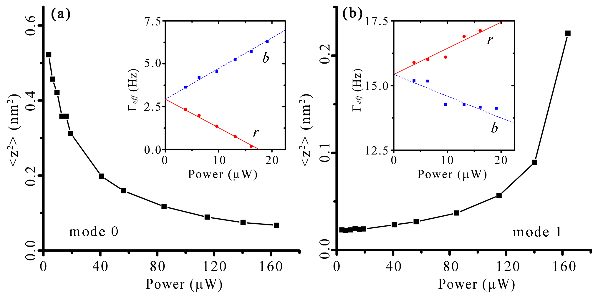
The deformable mirror of FP cavity formed by the compliant micro-cantilever is subject to action of optical forces. It in turn modulates the stored optical energy and results in the optical forces backaction on the oscillation of micro-cantilever as a consequence. The mutual modulation between the laser field inside the cavity and the motion of micro-cantilever forms the foundation of passive optical cooling. Under the low cavity fineness condition, only the retarded backaction of photothermal force (or bolometric backaction) participates in optomechanical cooling 21 . Other optical forces, such as radiation pressure, react instantaneously with the oscillation of micro-cantilever, thus modify only the resonant frequency. Depending on the detuning condition of micro-cavity, the thermal oscillation of the micro-cantilever can be either enhanced or suppressed. However, the direction of bolometric backaction is mechanical mode dependent. As shown in Fig.2, cooling operation on the fundamental mode (mode 0) always accompanies the warm-up of mode 1 at position P3 indicated in Fig.1(c). Its thermal oscillation is enhanced continuously with laser power increasing. Once crossing the threshold of =0, mode 1 will be driven into self-sustained oscillation. This result is in consistent with the observation in the work by G. Jourdan et al 24 .
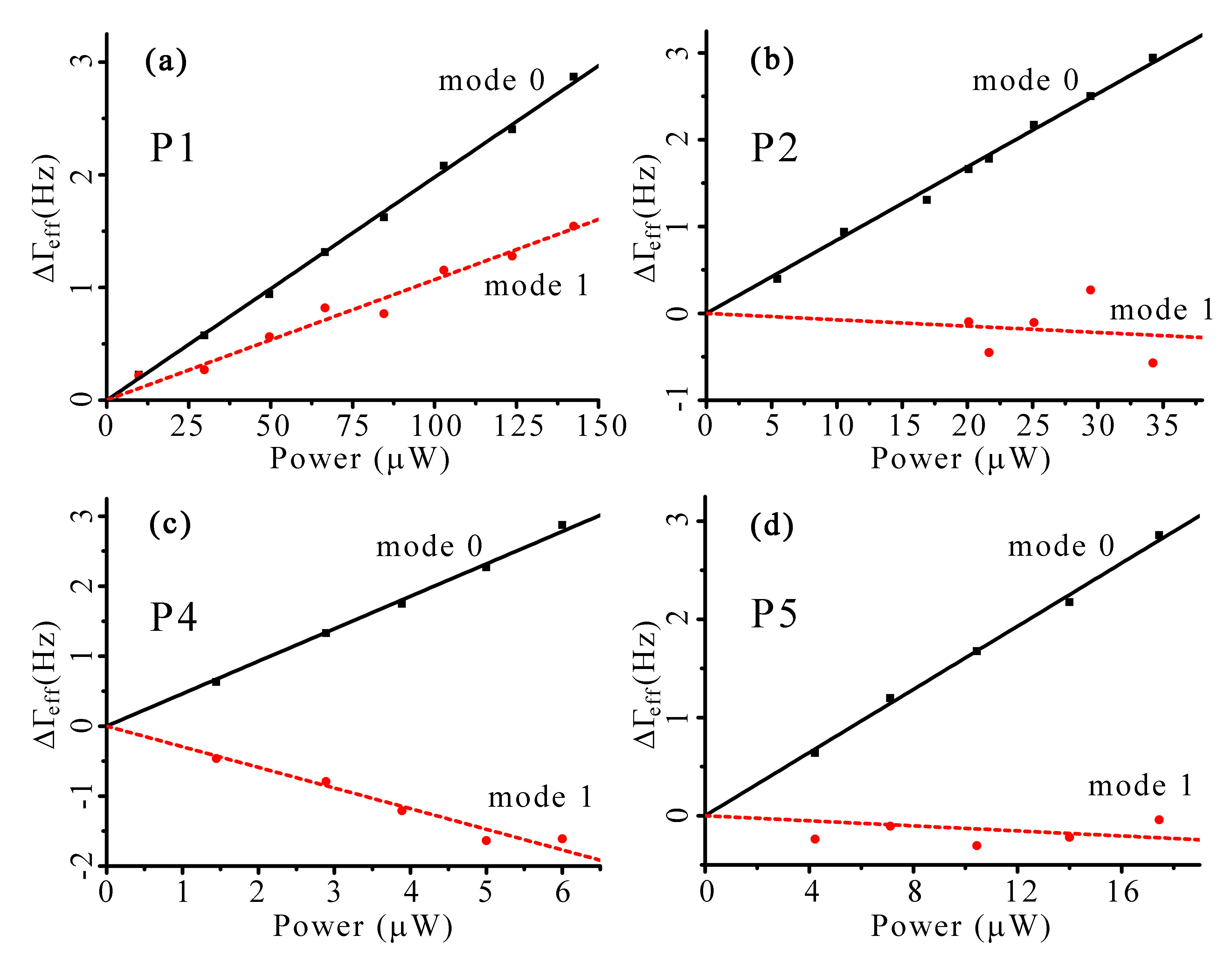
This mode dependent photothermal coupling is investigated further at other LSPs denoted in Fig.1(c). The photothermal damping for mode n can be represented by , where and are the effective damping of micro-cantilever at working position b and r respectively. In the case of , mode n of the micro-cantilever is enhanced at blue cavity detuning while cooled at red cavity detuning, and vice versa for . For mode 0, is always a positive value, whereas its value changes with illuminating point for mode 1. As showed in Fig.3, it indicates a LSP dependent behavior in photothermal mode cooling. At position P1, the bolometric backaction is exerted on the two modes in the same direction. Depending on the detuning of cavity, it provides a possibility of cooling the two modes simultaneously. Although the bolometric backaction on mode 1 maintains its direction at those LSPs beyond the vibration node, its relative strength is varied evidently. The accompanied enhancement of mode 1 at position P2 and P5 is so weak that its influences become apparent only in the case of strong photothermal coupling. However, at position P3 and P4, mode 1 is excited obviously during cooling operation on mode 0.
In order to understand such LSP dependent behavior, we develop a simple model for the photothermal coupling. As long as the displacement of micro-cantilever from its equilibrium position is the summation of all mechanical modes, denoted by where is the shape of mode i, the motion equation for mode n of micro-cantilever driven by both thermal force Fth and bolometric force Fbol can be expressed as
| (1) |
where m, E, and Kn are the effective mass, Young’s modulus, damping factor and spring constant of mode n respectively 24 . The integration term includes the photothermal stress generated all along the length L of the micro-cantilever. A detailed understanding of the moment of inertia is extremely difficult, because the dynamic temperature field inside the lever body is intricate, which depends on the optical and thermal properties of lever materials, structural geometry, environment temperature, laser wavelength and so on. For our gold film coated micro-cantilever, the photothermal force originates primarily from the different thermal expansion coefficients between gold film and silicon material of the lever. The small temperature variation through the thickness of micro-cantilever is therefore negligible 27 . Providing the small width of the micro-cantilever as comparing with the laser spot profile, the temperature distribution can be reduced to a one dimension field for this composite lever structure. In the limit of small oscillation amplitude, the oscillation modulated laser intensity I(z) is approximated by the Taylor expansion around equilibrium position z0: . Thus the laser induced dynamic temperature field along the micro-cantilever can be described as:
| (2) |
A is the absorptivity of laser power. The retarded backaction of photothermal force is described by the response function , where is referred to as the delay time constant of bolometric backaction 21 . This expression generally takes the contribution of all mechanical modes into account.
Since the photothermal coupling to higher order mechanical modes is attenuated by the low pass filter behavior of bolometric backaction, in this letter, we consider the contribution of the first two modes only. Combining Eq.1 and Eq.2, the Fourier transform yields:
| (3) |
where is cavity detuning condition dependent. In particular, when working position inside the micro-cavity changes from blue detuning point b to the adjacent red detuning point r, the slope of interference is reversed and hence changes its sign. The mechanical mode dependent behavior of bolometric backaction is introduced by the function . Since the temperature profile is concentrated around the LSP 28 , it functions to window the contribution of mode shape in the vicinity of the laser illumination point only, which decides the LSP dependent nature of photothermal mode cooling. As Eq.3 describes, photothermal coupling involves both self-coupling and inter-modes coupling for each mechanical mode, which are represented by the diagonal terms and non-diagonal terms of the matrix, respectively. The contribution of inter-modes coupling is typically overwhelmed by the self-coupling. Thus, the responses of the micro-cantilever are dominated by the self-coupling terms, with the resonant frequency and damping factor modified by the real and imaginary part of bolometric backaction accordingly. Providing the relatively small frequency shift, the relative photothermal cooling effect of mode n with respect to fundamental mode can be represented by the photothermal damping ratio , which is defined as:
| (4) |
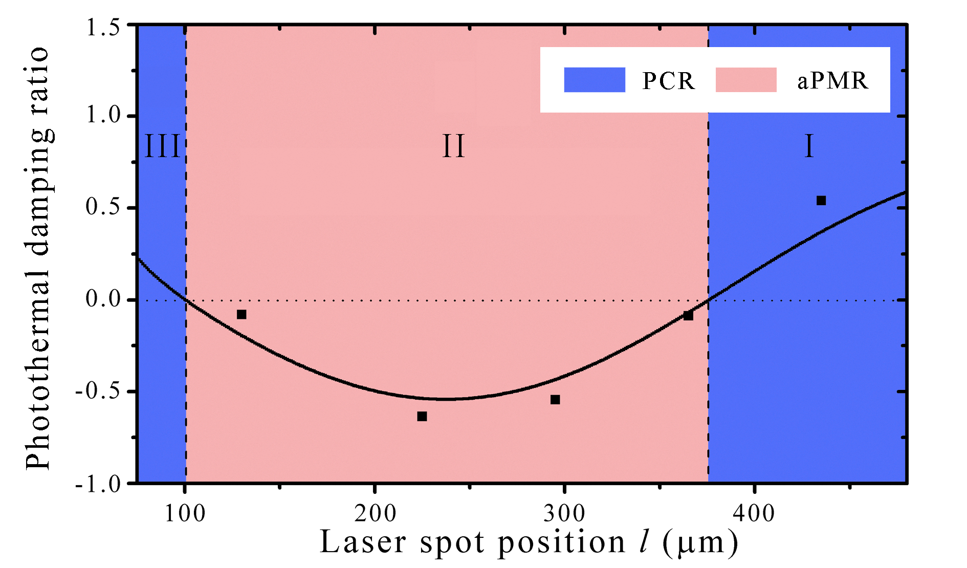
Either the bolometric backaction acting in opposite directions on the two modes simultaneously or not depends completely on the sign of . Simulation shows that three functional regions of two types, the PCR and aPCR, are divided for mode 1 along the micro-cantilever by two nodes, as illustrated in Fig.4. In region I, bolometric backaction applying onto the two modes of the optomechanical resonator in the same direction results in a parallel coupling. Crossing the vibration node of mode 1 such that the sign of is changed, reversing of the vibration phase results in altering the direction of bolometric backaction. Operating in the aPCR of region II, damping of one mode always accompanies with the enhancement of the other at the same time. It is not surprising that locally laser heating imposes the second node in the vicinity of the position , which imposes the other boundary of aPCR. Beyond this node, in region III, the mode dependent coupling function changes its sign, whereas mode function does not. It leads to the second PCR along the micro-cantilever. By positioning the laser beam into the PCR, simultaneous cooling of the two modes is achieved at blue cavity detuning condition. The delay time constant , which sets the cutoff frequency for the bolometric backaction, is calculated to be 2.5ms for our micro-cantilever at room temperature 21 . To obtain a more efficient cooling, the dimension of the micro-cantilever should be designed according to experiment temperature to satisfy the optimal cooling condition of .
It is worth noted here that even higher order mechanical modes of micro-cantilever may become significant in strong photothermal coupling condition. The photothermal cooling involving higher order mechanical modes can also be analyzed in the same principle. For higher modes, we predict theoretically that the micro-cantilever could still be divided into three functional regions, with both boundaries of aPCR expanding towards two ends of micro-cantilever continuously as the order of mechanical modes increases as a result. However, the details inside aPCR become increasingly complicated for higher order modes, which introduce more nodes within aPCR and emphasize the necessity of a more accurate description of the temperature field distribution.
In conclusion, by positioning the laser beam onto different points along the FP optomechanical resonator of the gold film coated micro-cantilever, we have investigated the LSP dependent behavior of photothermal mode cooling. Experiments show that not only the direction but also the efficiency of photothermal mode cooling is LSP dependent. According to the direction of bolometric backaction, we divide the micro-cantilever into three coupling region of two types, the PCR and aPCR. Simultaneous cooling of the first two modes can be achieved when laser beam is pointed onto the PCR of micro-cantilever. After satisfying the optimal cooling condition such that the residual thermal effect is minimized, photothermal cooling limitation may ultimately reach by illuminating the micro-cantilever at the cross section of the PCRs of the first few mechanical modes.
This work was supported by the Grand Project of Instrumentation and Equipments for Scientific Research of the Chinese Academy of Sciences under contract YZ0637. We gratefully acknowledge Y. Miyatake in Unisoku Scientific Instruments for technical supports.
References
- (1) Haixing Miao et al., Phys. Rev. A 81, 012114 (2010).
- (2) D. Vitali et al., Phys. Rev. Lett 98, 030405 (2007).
- (3) W. Marshall, C. Simon, R. Penrose and D. Bouwmeester, Phys. Rev. Lett. 91, 130401 (2003).
- (4) T. Rocheleau et al., Nature (London) 463, 72 (2010).
- (5) A. Naik et al., Nature (London) 443, 193 (2006).
- (6) H. Miao, S. Danilishin and Y. Chen, Phys. Rev. A. 81, 052307 (2010).
- (7) H. Fu, Y. Liu, J. Chen, and G. Cao, Sens. Actuators A 163, 533 (2010).
- (8) S. Kuehn, S. A. Hickman and J. A. Marohn, J. Chem. Phys. 128, 052208 (2008).
- (9) M. D. Lahaye, O. Buu, B. Camarota and K. C. Schwab, Science 304, 74 (2004).
- (10) M. A. Macovei, Phys. Rev. A. 81, 043411 (2010).
- (11) P. Zhang, Y. D. Wang, and C. P. Sun, Phys. Rev. Lett. 95, 097204 (2005).
- (12) K. Xia, and J. Evers, Phys. Rev. Lett. 103, 227203 (2009).
- (13) M. Poggio, C. L. Degen, H. J. Mamin, and D. Rugar, Phys. Rev. Lett. 99, 017201 (2007).
- (14) F. Marquardt and S. M. Girvin, Physics 2, 40 (2009).
- (15) T. J. Kippenberg and K. J. Vahala, Science 321, 1172 (2008).
- (16) Y. S. Park and H. Wang, Nature Phys. 5, 489 (2009).
- (17) A. Schiliesser et al., Nature Phys. 5, 509 (2009).
- (18) S. Groblacher et al., Nature Phys. 5, 485 (2009).
- (19) I. Favero and K. Karrai, Nature Photonics 3, 201 (2009).
- (20) D. Klechner and D. Bouwmeester, Nature (London) 444, 75 (2006).
- (21) C. Metzger, I. Favero, A. Ortlieb and K. Karrai, Phys. Rev. B 78, 035309 (2008).
- (22) C. H. Metzger and K. Karrai, Nature (London) 432, 1002 (2004).
- (23) I. Favero et al., Appl. Phys. Lett. 90, 104101 (2007).
- (24) G. Jourdan, F. Comin and J. Chevrier, Phys. Rev. Lett. 101, 133904 (2008).
- (25) Y. Liu et al., 5th IEEE international conference on nano/micro engineered and molecular systems, 633 (2010).
- (26) K. J. Bruland et al., Rev. Sci. Instrum. 70, 3542 (1999).
- (27) J. R. Serrano, L. M. Phinney and J. W. Rogers, Int. J. Heat Mass Transfer 52, 2255 (2009).
- (28) G. C. Ratcliff, D. A. Erie and R. Superfine, Appl. Phys. Lett. 13, 1911 (1998).