LOFAR-UK
Abstract:
The LOFAR-UK station at Chilbolton has recently been completed and significantly increases the angular resolution of the International LOFAR Telescope, as well as providing a unique training site and testbed for british experience with next-generation software telescopes. The station has been funded primarily through the LOFAR-UK, the largest astronomy collaboration in Britain, as well as via the South East Physics Network (SEPNET) and STFC. In this brief paper we discuss the history and organisation of LOFAR-UK, provide a technical description of the Chilbolton site, and discuss how LOFAR stations can be augmented by the addition of extra local processing capabilities such as ARTEMIS.
1 LOFAR
LOFAR (www.lofar.org) is a ‘next generation’ radio telescope operating at the low frequency (30–240 MHz) end of the radio spectrum. The telescope will be more than two orders of magnitude more sensitive than previous observatories in this frequency range, a dramatic increase facilitated in large part by advances in computing power and data transport, hence the use of the term ‘software telescope’. LOFAR is also the largest low-frequency pathfinder for the Square Kilometre Array (SKA, www.skatelescope.org). The project is led by ASTRON and most of the collecting area (%) is in The Netherlands.
International stations are important for LOFAR both scientifically because they improve the angular resolution of the telescope, and politically because they draw international partners into the project. LOFAR stations separated by large distances also act as useful anti-coincidence tests against local RFI when making wide-field searches for fast transients. On 12 June 2010, at the official inauguration of LOFAR, the Memorandum of Understanding (MoU) of the International LOFAR Telescope (ILT) was signed by partners from The Netherlands, Germany, Sweden, France and The United Kingdom. On 9 November 2010 the ILT Foundation came into existence and LOFAR can genuinely be said to be a pan-European project, with the UK as one of its founding members.
2 LOFAR-UK

2.1 Background
The LOFAR-UK (www.lofar-uk.org) consortium was created in 2006 with the goal of securing UK involvement in LOFAR. The aim was to purchase, construct and connect one or more LOFAR stations and in this way allow UK involvement in LOFAR science, mainly via the existing Key Science Projects (KSPs). The case for UK participation in LOFAR was presented in the LOFAR-UK white paper (Best et al., 2008). By 2009 over 20 UK institutions had joined the project, directly committing resources to the project (in most cases funding at the level of GBP 50k). The research council site at Chilbolton (www.chilbolton.rl.ac.uk), in the south of England, was identified as the prefered site for the station, although equally good sites at Jodrell Bank and Lord’s Bridge were also considered. Significant funding (GBP k) was also provided to the project by the UK South East Physics Network (SEPnet, www.sepnet.ac.uk), which identified LOFAR as its key astrophysics theme. Figure 1 illustrates the breadth of the consortium.
In early 2010, the Science and Technology Facilities Council (www.scitech.ac.uk) also made a significant contribution (GBP k) and agreed to cover operations costs in 2011 and 2012. At this point the contract was signed with ASTRON and construction began at Chilbolton. At the time of writing (March 2011), construction of the station is complete, the fibre connection to the correlator in Groningen is complete, and scientific commissioning of both international array and ‘stand-alone’ operations has begun.
2.2 Chilbolton
The site chosen for the LOFAR-UK station was the Chilbolton Observatory. This is an existing Science and Technology Facilities Council (STFC) facility run by the Chilbolton Group of the Rutherford Appleton Laboratory. The site is located on the edge of the village of Chilbolton near Stockbridge in Hampshire, England. Apart from the necessary land area, the site has a good aspect and all the necessary scientific infrastructure to accomplish the project.
The LOFAR facility installed is what is referred to as an International Station. It comprises two fields of antennas. They are the High-Band Array (HBA) and Low-Band Array (LBA), with the high and low referring to the frequency ranges. The LBA comprises 96 aerials set out in a pseudo-random pattern with a diameter of approximately 70m. Each aerial stands 1.8m tall, with two crossed, sloped dipoles. The nominal frequency range of the LBA system is 30 to 80 MHz, although observations have since been successfully carried out beyond this range, as low as 22 MHz.
The HBA comprises 96 square tiles, 5 by 5 metres in size with a height of 0.5m. Each tile is split into 16 cells containing crossed-bowtie antennas. Each tile has its own analogue beamformer to combine the signals from the cell antennas. The outputs of the 96 tiles can then be treated as individual antennas in the same way as the LBA. The HBA system covers the 120 to 240 MHz range. A 97th passive tile is located in the centre for RF-balancing and wind-loading reasons; it has no signal output (it is indicated by a C in Fig 2).
The 80 to 120 MHz spectral region is the allocated band for FM radio broadcast and the LOFAR system is designed to suppress this spectral region. The antenna fields are enclosed within a perimeter fence, made of timber and synthetic mesh to minimise the RF impact. The fence prevents incursions by wildlife or stock onto the antenna field.
Also within the enclosure there is a converted 20-foot (6.1 m) shipping container with air-conditioned Faraday enclosure holding the digital signal processing electronics. Two coaxial cables connect each aerial and tile to the central RF-container. These carry the analogue RF signals, as well as DC power and low-baud control signals.
From the RF container, there is an optical fibre which carries the digital data to the main observatory buildings. A further network interface there completes the connection of the local system to a commercial fibre routed offsite. This link extends to Groningen in the Netherlands, which is where the Central Processing (CEP) supercomputer facility is located.

2.2.1 Construction history
Installation work was carried out during the summer of 2010. The project management, site supervision and quality assurance was carried out by STFC staff, with the primary contractors for the ground works being Kier-Moss and subcontractors Coral Constructors. Antenna hardware was supplied by Autonational and RF electronics installation was carried out by Excel assemblies (both under contract from ASTRON). After an initial planning phase, ground works commenced on 17 March 2010. In early June, the LBA aerials were installed with the support of students of local universities. The following month, the HBA tiles were installed with assistance from U. Manchester and U.Cambridge. A SEPnet data acquisition system, developed and installed by U.Oxford (see section 2.3) demonstrated a working system in early September and the facility was officially opened by Dame Jocelyn Bell Burnell on 20 September 2010. The station’s official designation is UK608.
Construction and project management at Chilbolton was led by Derek McKay-Bukowski (SEPnet / STFC).
2.2.2 Timeline
The following is a timeline of important events in the construction and commissioning of UK608 Chilbolton.
| 17-Mar-2010 | Start of ground works |
| 19-Apr-2010 | RF-container placed in final location |
| 18-May-2010 | Laying of all antenna signal cables complete |
| 07-Jun-2010 | Start of LBA aerial deployment |
| 11-Jun-2010 | LBA installation complete |
| 02-Jul-2010 | Start of HBA tile deployment |
| 14-Jul-2010 | HBA installation complete |
| 15-Jul-2010 | Electronics in RF container installed |
| 01-Sep-2010 | First signal from antenna to fibre |
| 06-Sep-2010 | First pulsar detected using local computing |
| 20-Sep-2010 | Site officially opened by Dame Jocelyn Bell Burnell |
| 12-Oct-2010 | Network installation and offsite fibre |
| 09-Dec-2010 | First network packet at 10 Gbit/s from site to CEP |
| 11-Jan-2011 | First fringes between UK608 and Dutch core stations |
| 18-Jan-2011 | Observations for first long-baseline image |
| Antenna: | 96 sloped crossed-dipoles |
| Polarisations: | 2 linear |
| Longitude: | 1.433500703 deg W |
| Latitude: | 51.143833512 deg N |
| Mean height: | 176.028 m |
| Diameter: | 70 m (approx) |
| Array: | 96 tiles |
| Tile: | 16 crossed-bowtie |
| Polarisations: | 2 linear |
| Longitude: | 1.434454726 deg W |
| Latitude: | 51.143546200 deg N |
| Mean height: | 177.048 m |
| Diameter: | 62 m (approx) |
2.3 Artemis
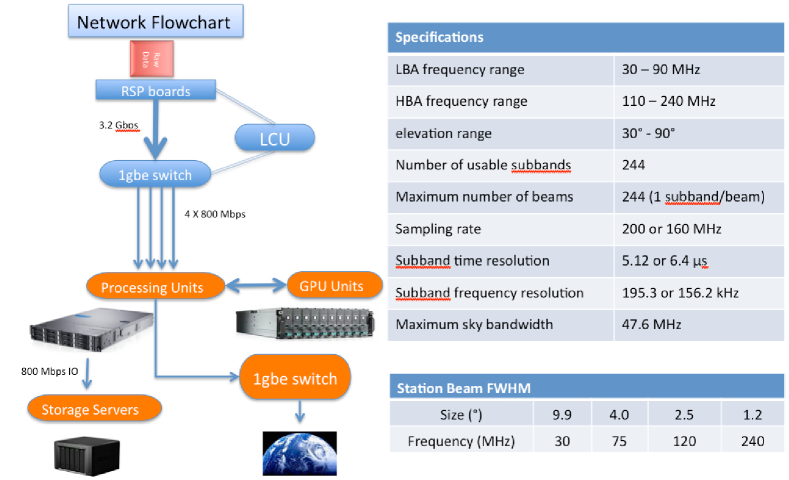
During the last year, a team from Oxford Astrophysics and the Oxford e-Research Centre, has put together an instrument capable of processing the beamformed data from international LOFAR stations, with the main objective to conduct large field of view surveys for fast radio transients. The instrument, code-named ARTEMIS (Advanced Radio Transient Event Monitor and Identification System, and ancient Greek goddess of hunting), has been demonstrated to successfully process the full 3.2 Gbps streaming bandwidth generated by the LOFAR station in Chilbolton UK. Fig 3 presents a flow diagram for ARTEMIS. This flow of data is split into four 800 Mbps streams, each of which is fed into a high performance server, connected to eight high-end NVIDIA Tesla graphics cards (C1060). The servers are capable of reading, and processing the data in real-time, with the possibility to flag interesting events and also write out to disk or to a network stream. The processing involves RFI excision, detection, integration and dedispersion, which are all separate parts of a modular software pipeline.
The ARTEMIS backend can behave both as a general purpose backend for the science targets mentioned above, and specifically for the detection of transients - the latter can also operate commensally with other possible LOFAR observations. Furthermore, ARTEMIS is telescope agnostic; it was designed and built with LOFAR in mind, but can be easily adapted to fit other instruments. For example the newly constructed EMBRACE aperture arrays, which even share some of the electronic component design of LOFAR can be exploited by fitting an ARTEMIS backend to record or process data on the fly. Both EMBRACE and the LOFAR arrays are pathfinders for the SKA, and ARTEMIS is designed as an expandable solution.
The ARTEMIS project is led by Aris Karastergiou (Oxford).
3 The future
At the time of writing Chilbolton has completed its first test observations as both a stand-alone station and as part of the ILT (see timeline above). The coming year will also be mainly devoted to testing and commissioning, with a number of further stand-alone observations (including pulsars, SETI work, solar observations, searches for bright, rare transients) and long-baseline tests as part of the ILT. In the very near future STFC will sign bilateral agreement for operations with ASTRON, on behalf of LOFAR-UK. Many tens of british scientists are already involved in analysis of LOFAR data, and this number is growing fast.
The LOFAR-UK collaboration should, furthermore, act as an indicator of the strong and diverse interest in ‘next generation’ radio astronomy across the UK. This can become a model for how we build national interest in a strong and energetic scientific community for participation in the Square Kilometre Array.
Acknowledgements
LOFAR-UK would like to acknowledge the invaluable work provided, mostly for free, during the construction of the LOFAR-UK station at Chilbolton by an army of PhD students, postdocs and staff.
References
Best P., and the LOFAR-UK consortium, LOFAR-UK White Paper: A Science case for UK involvement in LOFAR, arXiv:0802.1186