Effect of orbital symmetry of the tip on Scanning Tunneling Spectra of Bi2Sr2CaCu2O8+δ
Abstract
We discuss how variations in the scanning tunneling microscope (STM) tip, whether unintentional or intentional, can lead to changes in topographic images and dI/dV spectra. We consider the possibility of utilizing functionalized tips in order to improve the sensitivity of STM experiments to local irregularities at the surface or hidden below the surface layers. The change in the tip symmetry can radically alter the contrast of the topographic image due to changes in tip-surface overlap. The dI/dV curves change their shape according to which sample bands the tip orbital tends to overlap. In addition, relative phases between competing tunneling channels can be inverted by changing the tip symmetry, which could help reveal the origin of a local irregularity in tunneling spectrum.
pacs:
68.37.Ef 71.20.-b 74.50.+r 74.72.-hI Introduction
Scanning tunneling microscopy and spectroscopy (STM/STS) are extensively used to probe the quasiparticle spectra of high temperature superconductors, especially of the cuprate materials such as Bi2Sr2CaCu2O8+δ (Bi2212)Fischer ; McElroy ; Hudson ; Pan ; Yazdani . These studies have contributed immensely in obtaining insight into superconducting and pseudogap phases of these materials owing to the very high spatial and energy resolution of the spectroscopy. The full experimental potential of STM/STS is, however, far from exploited, since the chemical and spatial resolution as well as the directional selectivity could, in principle, be improved by overcoming various challenges related to intrinsic properties of STM.
The first challenge is related to the fact that the signal from superconducting layers is filtered by insulating oxide layers. In addition, the signal does not arrive at the microscope tip directly from the site below the tip but rather through symmetry driven tunneling channels. Hence, experimentally observed spectral features are not only distorted by filtering, but ascertaining their spatial origin becomes harder the deeper within the sample is their source. Another factor to be aware of is that the electronic and geometrical properties of the microscope tip may also affect STM images. In standard interpretation, the tip is assumed symmetric to rotations around the vertical axis (‘s-wave’). The relative bluntness of the tip suggests this assumption and, furthermore, the metallic nature of common tip materials does not favor oriented “dangling” orbitals, and specific effects of tip geometry and electronic structure are usually ignored. However, this interpretation has been challenged by a variety of sophisticated theoretical studies cjchen ; chaika ; sacks , which, on the one hand show that the closer the tip is to the surface, the more important the symmetry of tip orbitals is to the STM image and, on the other hand, they indicate that s-wave tips might not be able to produce images with atomic resolution. Notably, the relative importance of tip orbitals with different symmetries in the STM signal can be controlled by varying the tip-surface distance, or alternatively, by functionalizing the tip by attaching particular atoms/molecules at the apex of the tip.
In various experimental studieseigler ; hahn ; bartels ; bartels_prl_1998 ; lee_science_1999 ; lagoute_prb_2004 ; repp_prl_2005 ; deng ; cheng , the tip properties have been deliberately modified for better spatial or chemical selectivity by picking up a molecule, e.g. CO, O2 or N2, from the surface to the apex of the tip after which the plain tip results have been compared to the results with a functionalized tip. This has proven to improve chemical selectivity in adsorbate on a solid surface system since each surface species responds in an individual way to the change of tip symmetry due to functionalization. Even in the case of relatively complicated molecules, such as pentacene attached to the tip, the contrast of differential conductance maps revealing the geometric shape of molecular orbitals is surprisingly sharpened repp_prl_2005 by the enhanced directionality of the probe-sample overlap due to the dominance of the or type localized orbitals closest to the sample surface. The idea of utilizing a functionalized tip is further encouraged by the fact that the resolution of atomic force microscopy (AFM) studies is enhanced by using CO molecule attached to the metallic tip AFM_CO , although improving the resolution and selectivity in the case of AFM has a different physical basis from STM.
The preceding work on molecular adsorbate systems provides motivation
for considering functionalized tips for investigating cuprate
materials, where the interesting physics is found at layers not
immediately on the surface. We can foresee many uses of functionalized
tips in probing these materials. An obvious application would be a
more accurate probe for the surface properties. In the case of Bi2212,
to date one has mostly observed the Bi atoms of the surface layer in
topographic STM images. Information from the oxygen atoms of the
surface layer has been difficult to obtain, and hence STM provides
limited ability to observe the real symmetry of the surface. A more
involved application is related to the dI/dV spectra. As shown in our
previous studiesnieminenPRB , the spectra are mappings of the
electronic structure of the cuprate layer, filtered by the BiO and SrO
layers, which sit on top of the cuprate layers. Although the signal
can be theoretically resolved into partial signals of different
origin, the STS experiment measures a signal combined from different
sources and, furthermore, the information from different directions in
momentum space is integrated into a single outgoing signal. A possible
means of decomposing the STS spectrum experimentally is to measure
topographic spectral maps. In practice, real space and Fourier
transformed maps differentiating electron and hole states have been
produced in order to recognize direction dependent underlying
electronic order z_etc_maps . A third possible application would
be investigation of symmetry properties related to nematicity
transitions in the subsurface electronic structure at low values of
doping, where the oxygen atoms of CuO2 layers in different
directions appear non-equivalent below the pseudogap
transition temperature as shown in Ref. Kohsaka2007, .
In fact, functionalized tips may well have been used inadvertently in studies of Bi2212. It has been reported that tip resolution can improve dramatically after use, and it has been suggested that this may be due to the attachment of a Bi atom to the tunneling tip bifunct . Here we will explore the effects of tips, which are dominated by a single atomic orbital of varying symmetry. We find that such tips can not only couple with different surface orbitals, but can also affect the interference between tunneling channels from the cuprate layer to the microscope tip. This suggests possibilities for investigating irregularities within the cuprate layers, which are not directly accessible to the STM tip, and thus reveal features invisible to STM/STS experiments with a symmetric tip. In this way, our study advances the understanding of matrix element effects in STM.abfoot1 ; newarpes ; rixs ; Compton ; positron
This article is organized as follows. Section II briefly describes the model utilized in this study. Section III presents calculations of the effect of tip symmetry on topographical maps, STM corrugations and dI/dV spectra at various high symmetry sites. In Section IV we show how a hidden irregularity within the cuprate layer can be studied by comparing results obtained with different tip symmetries, among other results. Finally, conclusions are given in Section V.
II Description of the model
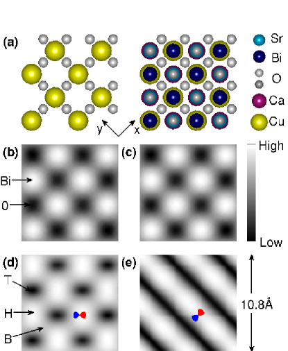
Although the model used is essentially the same as in Ref. nieminenPRB, , we provide an overview here for the sake of completeness. The simulation supercell consists of 8 unit cells that have been rotated degrees as shown in Fig. 1. The unit cell geometry is adapted from Ref. Bellini, . In total there are atoms and orbitals accounting for both spins. The topmost 7 layers below the cleavage plane are included, which are in descending order: , , , , , and . Depending on the atom type different sets of orbitals are included. For , and the orbital set is and for the orbital set is . has a single orbital. The Green’s function is computed in a supercell Brillouin zone at equally distributed k-points corresponding to k-points in the unit cell.
As shown in Fig. 1, we define the position of Cu (or surface Bi) atoms as top site (), the position of bonding O atoms of the cuprate layer as bridge site (), and the position of O(Bi) as the hollow site (). In this choice of geometry, the and orbitals point along the bond between the neighbouring Cu atoms, i.e., in the direction from the top site to the bridge site (), whereas the linear combinations point from the top site towards the hollow site (). Concerning the oxygen atoms related to the cuprate layer, the apical oxygen is at the top site, while the bonding oxygens between Cu atoms are at bridge sites.
The tip is modeled as a single orbital in order to highlight the effect of each type of tip symmetry on the STM/STS spectrum. We consider four different tip symmetries which can be divided into two groups. These consist of - and -orbitals, which are symmetric to rotation around z-axis, accompanied with two choices of horizontal -orbitals. We use a shorthand notation for a -orbital along the bond between two neighbouring Cu atoms, and for an orbital rotated by , i.e., aligned in the direction connecting next nearest neighbouring Cu atoms. These two horizontal tip symmetries can also be connected to the nodal () and antinodal () directions.
The Hamiltonian is the same as that used previously in our STM studies of optimally doped B2212NLMB ; nieminenPRB ; selffoot ; tanmoyop , where superconductivity is modeled with a pairing matrix between electrons and holes with opposite spins:
| (1) |
with real-space creation (annihilation operators) (). Indices are combination of site and spin indices. The d-wave symmetry of the superconducting gap is modeled by taking to be non-zero only between the neighbouring orbitals, and with opposite signs for - and -directions, which leads to a d-wave symmetric superconducting gap Flatte . The tight-binding parameters are taken to be doping-independent in the spirit of the rigid band model.abfoot2 ; new1 ; new2
The tunneling current is computed within the Todorov-Pendry approximation Todorov ; Pendry ; tunnelingfoot ; meirwingreen ; TH ; korventausta as
| (2) |
The hopping integrals depend on the symmetry of tip and surface orbitals as well as the distances involved through the Slater-Koster coefficientsSlater ; Harrison . The tip to surface distance is usually greater than the distance between the atoms in the bulk material. To allow for this the standard Slater-Koster method is enhanced by an exponential decay at large distances hoppingfoot . The Slater-Koster method allows one to take the directionality of both the tip and surface orbitals into account. It can be considered as a special case of the more general “derivative rule” of Chencjchen and a similar approach of Sacks and Noguera sacks who utilize derivatives of the real space tip wave function.
The difference between the two formulae is that Eq. (2) emphasizes the coupling between the tip and the surface orbitals expressed by the hopping integrals , whereas Eq. (3) makes more transparent how tunneling takes place through the filtering layers between the tip and the superconducting layers. Of course the symmetry of the tip itself is described by , but in order to recognize the relevant surface orbitals, it is essential to consider the filtering matrix elements, , as well.
The spectral function depends on both regular and anomalous Green functions as shown below
| (5) |
To conclude, the formulae given above provide not only the total spectrum, but also an explicit form of the filtering effect on the cuprate layer, and decompose the density matrix of the cuprate orbitals into regular and anomalous spectral terms.
III Results
III.1 Topographic maps
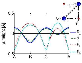
The topographic maps of Fig. 1(b-e) are calculated using Eq. (2) in constant current mode, i.e., there is a feedback loop varying the tip-surface distance in order to retain the tunneling current constant. For bias voltage we choose We also follow the common practice of accompanying topographic maps with corrugation curves in Fig. 2, since the latter reveal the absolute scale of the contrast otherwise obtained in a rather arbitrary way from topographic maps.
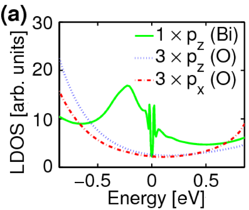
Experimental topographic maps typically resemble the calculated maps for s-wave tip with a high intensity at the position of the surface Bi atoms. Within the Tersoff-Hamann type analysis TH , a high intensity signal is attributed to a high local density of electrons. As Fig. 3(a) indicates, the surface Bi atoms have a large density of states over a wide range of energies around the Fermi energy. This was demonstrated already in our earlier work nieminenPRB where we further related this to the coupling between the orbitals of Bi and the orbital of the Cu atom below through the intermediate orbital of the apical oxygen. In contrast, orbitals of O(Bi) contribute to the BiO bands, which contain a gap around the Fermi-energy. In Fig. 3(a) these states are broadened since we have invoked a Fermi liquid type self-energy in the noncuprate layers ldafoot .
As seen in Figs. 1 (b) and 1 (c), tips with - as well as -symmetry expose the Bi atoms as bright spots. This is hardly surprising, especially in the case of the rather strongly oriented tip orbital. Our computations also suggest that symmetry slightly sharpens the contrast of the topographic map, but as shown in the corrugation curves of Fig. 2, the effect may not be experimentally significant. Tips with in-plane p-symmetry show striking changes in topographical maps. In the case where the tip orbital lies along the top-hollow (nodal) direction, (Fig. 1(c)), the contrast is inverted so that O(Bi) atoms appear as bright spots. However, as discussed further in Section IV below, visibility of oxygen atoms is spurious since the tunneling signal is still dominated by overlap between the horizontal tip orbital and the orbitals of Bi atoms. This is also the obvious reason why the bright spots in the topographical image lose their sharpness. The change in contrast becomes even more dramatic in the case of the tip orbital lying along the top-bridge (anti-nodal) direction, . As seen in Fig. 1 (d), the fourfold symmetry is now broken, and bright lines appear perpendicular to the orbital direction. In addition, intensity maxima are seen at bridge sites when the bonding oxygen orbital points to the same direction as the tip orbital. This indicates that in this case also the nature of the topographic image is driven the overlap between the tip orbital and the orbital of Bi atoms.
The intensity patterns in topographic images can be quantified as corrugation curves, such as those shown in Fig. 2. Interestingly, the horizontal tip orbitals not only invert the contrast of the topographic image, but they are also more sensitive to the horizontal position than tips with rotational symmetry around the z-axis. This is seen in the more strongly varying corrugation as the tip is scanned between the top, bridge and hollow sites. These differences, originating from the symmetry dependent nature of the tip-surface overlap, might be useful in pursuing a better lateral resolution in STM imaging.
Unfortunately, our theoretical predictions cannot be compared directly with measurements at this time since we are not aware of any experimental STM literature on Bi2212 where a deliberately functionalized tip has been deployed. However, some insight can be obtained by considering a study such as that of Ref. cheng, , which discusses the effects of attaching O2 functionalizing molecules to a tungsten tip for investigating a metal phtalocyanine monolayer on an Au(111) surface. Ref. cheng, finds selectivity with respect to molecular orbitals between normal and O2-functionalized tips, and observes the STM pattern of the adsorbate monolayer to rotate as different tips are used to probe the surface.
III.2 dI/dV spectra
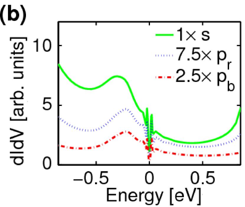
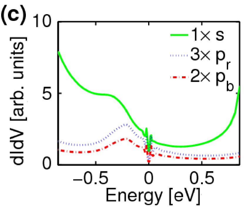
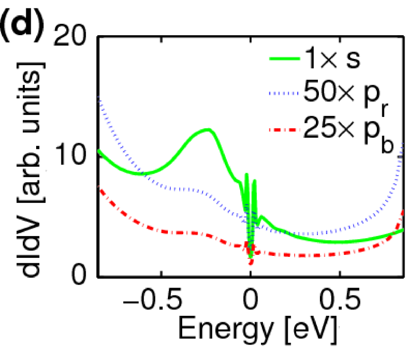
The shape and intensity of a spectrum depend on the tip symmetry as well as its position. In Figs. 3(b-d), the curves are calculated at vertical distance between the tip and the surface atoms. At this tip-surface distance, the gap features are clearly observed, and calculations indicate that the signal predominantly comes through the orbitals of the Bi atoms. There are clear changes in the VHS features at -0.15 to -0.4 eV with tip site and orbital symmetry: they seem to vanish for the s-wave tip at a hollow site, and for both the horizontal p-wave tip orbitals at a top site. The apparent reason for this is the increasing spectral weight of the BiO bands with increasing binding energy. These configurations seem to favour a relatively large overlap between the tip orbital and the p-orbitals of O(Bi) atoms. For an -wave tip on the top site, the curve resembles the Bi LDOS, as expected. However, this is also true for the horizontal -wave tips at the bridge or hollow site. These results support the conventional assumption that the experimental tips are predominantly -wave.
We note also a trend in the overall intensities of the spectra. As expected, horizontal p-symmetry of the tip orbital tends to decrease spectral intensity due to decreasing overlap. For s-wave symmetry, the intensity is highest for the top site and the lowest for the hollow site. For the horizontal p-symmetry, the top site gives the lowest intensity due to antisymmetry between of Bi and the tip-orbital. Moving the tip either to bridge or hollow site allows an increased overlap between the tip orbital and of Bi.
III.3 Impurity mapping and subsurface irregularities
dI/dV spectra are also used to detect and analyze hidden subsurface irregularities. These can include substitutional impurities, such as Zn or Ni replacing a Cu atom Hudson , or dopant atoms like oxygen, the fingerprints of which have been discussed both experimentally McElroy and theoretically Hirschfeld . However, perhaps the most fascinating potential application may be the nematic intracell symmetry breaking of the subsurface electronic structure observed at very low values of hole doping in the pseudogap phaseKohsaka2007 . This phase transition in the electronic order is not observed in the topographic images, but rather in maps and in the so called Z-maps derived from the differential conductance data. The relevance to the present theoretical considerations arises from the fact that the subsurface bonding oxygen atoms in CuO2 appear non-equivalent when this low-symmetry phase is mapped. We propose that breaking the symmetry of the tip by functionalization would give additional information about the nematic phase. Note that the observed patterns are difficult to interpret due to the filtering effect of the BiO and SrO layers. It is interesting therefore to explore whether different tip symmetries can provide insight by probing different tunneling channels. In earlier worknieminenPRB we showed that the bonding oxygens of the CuO2 layers are invisible to a spherically symmetric tip placed right above that atom. Hence we choose a local perturbation at this bonding oxygen. The simplest kind of perturbation is a change of the onsite energy, which could be induced by a be nearby dopant atom.
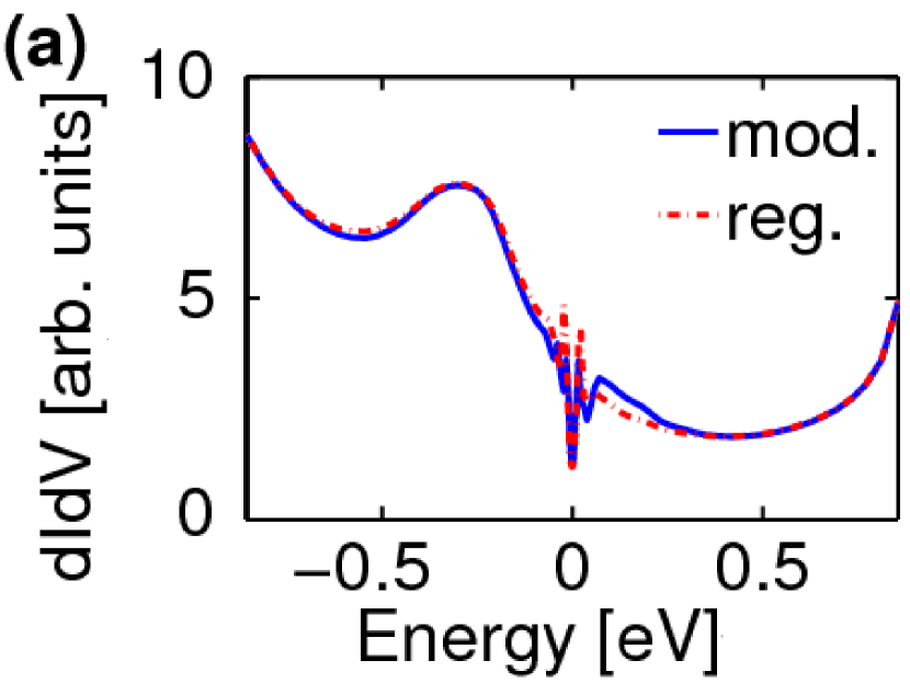
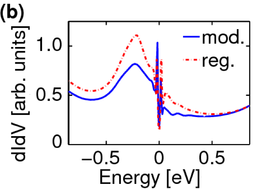
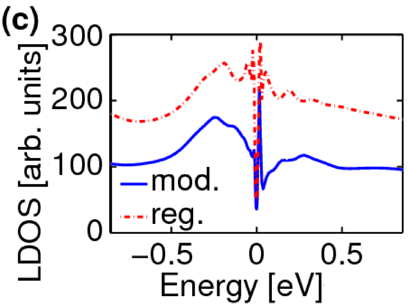
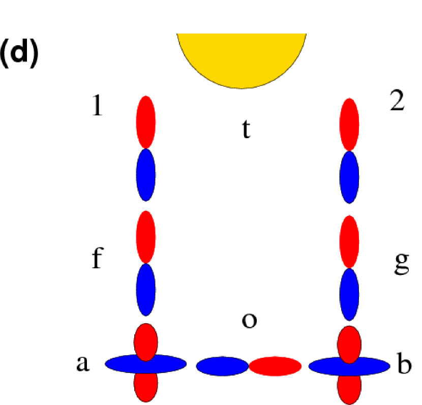
Figure 4(d) shows a tunneling tip positioned above a bonding oxygen in the cuprate layer, equivalent to the bridge site of Fig. 1. To simulate the effect of a nearby impurity, we modify the onsite energy of the -orbital along the bond by -2.0 eV.perturfoot In Fig. 4(c) we compare its LDOS (blue line) to that of the regular site (red line). The dI/dV spectra from the bridge site with and without onsite modification are plotted for (Fig. 4 a) and (4(b)) type tips to demonstrate how the impurity effect modifies the spectrum in different tunneling channels. Although the difference between the two LDOS results is striking (Fig. 4(c)), the spectra obtained by a rotationally symmetric tip do not reflect this difference. This can be explained by the results of Ref. nieminenPRB, , where we showed that two tunneling channels in antiphase are open between the oxygen and the tip (Fig. 4(d)), causing destructive interference between the corresponding signals. [The observed signal comes from different channels involving the Cu atoms.]
In Fig. 4(d) we show the dI/dV curve measured by a tip with orbital, and a clear difference is seen between the spectra of the regular and perturbed oxygens. The shapes of LDOS (b) and the spectra (d) are not identical, but the relative change of the spectrum follows that of LDOS, especially over the range between The change in the spectrum of Fig. 4(d) is caused by a reversal of the relative phase between the two tunneling channels in Fig. 4(a) due to p-type symmetry of the tip, a point to which we will return below. This result suggests that experiments probing the breakdown of symmetry, such as those in Ref. Kohsaka2007, , could be further clarified by varying the tip symmetry.
IV Analysis
IV.1 Tip symmetry and contrast changes in the STM map
A proper understanding of the observed topographical images and spectra requires an analysis of the filtering matrix elements which describe the coupling between the tip and the surface orbitals, propagation across the oxide layers, and coupling between the superconducting cuprate layer and the covering oxide layers. Starting from the latter, the cuprate layer is coupled to the oxide layers mainly through the overlap between the orbitals of the Cu atoms and the orbitals of the apical oxygen above. The propagation through the oxide layers is mediated by orbitals of the apical oxygen and the Bi atom above on the surface. When the tip symmetry is varied, the relevant factor is that of the surface Bi is the dominant surface orbital mediating the signal from the cuprate layer to the microscope tip. Hence, the analysis of the observed results can be built on the overlap between the tip orbital and the orbitals of the Bi atoms in the vicinity of the tip. While other surface orbitals are present, they are not strongly coupled to the cuprate bands, and hence they have a relatively low spectral weight in the vicinity of the Fermi energy. Thus, the horizontal p-orbitals of Bi and O(Bi) atoms are the dominant orbitals of the BiO bands related to the “bismuth pocket” states above Fermi-level and the corresponding valence bands below the “spaghetti” of bands (Fig. 3(a))bifoot .
Since only the Bi surface orbital is important, the analysis of the various tip orbitals is rather straightforward. The and -orbitals couple best on the top site, as seen in Fig. 3(b). For the horizontal tip orbitals, the overlap between the tip and of a surface Bi is lowest when the tip is directly above the Bi atom. In the case of both the bridge and hollow sites seem to give a large overlap between tip orbital and of Bi, but the hollow sites appear brighter since the overlap between the horizontal p-orbitals contributing to BiO bands is larger at this site. For the fourfold symmetry is broken. Since the orbital is oriented along the bonds between Cu atoms, there is a zero overlap line when following the bonding direction perpendicular to the orbital orientation. On the other hand, overlaps strongly with the two Bi atoms at the bridge site in the antinodal direction of . Moving towards the vicinal hollow sites preserves the strong overlap. At the hollow site, a strong overlap with four Bi atoms can be found. Since the distance is -fold as compared to the bridge site, overall the overlap remains roughly the same when moving from the bridge site to the hollow site, resulting in bright and dark stripes in Fig. 1(e).
IV.2 Hidden irregularities and the relative phase between two tunneling channels.
We consider the possibility of analyzing subsurface irregularities by functionalizing the tip. This may be possible if the interference between two different tunneling channels can be controlled. As an example, let us consider the situation where the tip is at the bridge site (see Fig. 4 (d)), i.e., above an oxygen atom in the CuO2 layer at an equal distance from the two neighbouring Bi atoms ( and ). This opens two channels from the CuO2 layer ( orbitals of Cu atoms and ) with filtering matrix elements and which are equal apart from a phase factor. It is obvious that and are equal in the case of - or -symmetric tip, since in that case , but the opposite sign is obtained with horizontal -orbitals.
To consider interference effects, we also need to compare elements of the spectral function
where denotes the p-orbital of the oxygen along the bond between the Cu atoms. It is evident that the p-symmetry leads to an antiphase between elements and , and hence the two first spectral terms are equal to each other, but the last one has the opposite sign.
| (6) |
It is clear that ’-’ sign on the right hand side of Eq. (6) applies to the case with , i.e., the - or -symmetry. Hence the oxygen below the tip would be invisible in STM. On the other hand, constructive interference is obtained for horizontally -symmetric tip. This should emphasize any variations in the horizontal p-orbital of the bonding oxygen. The situation is of course reversed if the bonding oxygen is replaced by an -wave symmetric perturbation, i.e. there is a constructive interference for - and -symmetric tips. This explains our comparison of a spectrum at the bridge site for unperturbed system with a vacancy at the site of the bonding oxygen.
With regard to the transition, the main practical conclusion of our analysis is that obtaining information related to the non-equivalent bonding oxygens can be enhanced by manipulating the tip symmetry by functionalizing molecules. This suggests that an s-wave symmetric tip gathers the signal from a neighbourhood of the bonding oxygen below, while a p-wave tip should be more selective to the on-site oxygen orbitals.
V Conclusions
We have investigated the effect of different tip symmetries on topographic STM images and dI/dV spectra. The change in tip symmetry can lead to contrast inversion and even to the breaking up of the symmetry due to strong differences in the nature of the tip-surface overlap. Furthermore, the corrugation curves show that the horizontal p-orbitals at the apex of the tip would be more sensitive to position of the surface atoms. The dI/dV curves reveal the leading sample states (CuO2-band, BiO-band or some more localized states) to which different symmetries tend to couple. More strikingly, changing the symmetry of the tip can be used to change the relative phase between two open tunneling channels. This could be applied to detect subsurface irregularities which would otherwise be invisible to STM.
Acknowledgments This work is supported by the US Department of Energy grant DE-FG02-07ER46352 and benefited from the allocation of supercomputer time at NERSC and Northeastern University’s Advanced Scientific Computation Center (ASCC). I.S would like to thank Ulla Tuominen Foundation for financial support. This work benefited from resources of Institute of Advanced Computing, Tampere. Discussions with Matti Lindroos are gratefully acknowledged.
References
- (1) Ø. Fischer, M. Kugler, I. Maggio-Aprile, and Chr. Berthod, and Chr. Renner, Rev. Mod. Phys. 79, 353 (2007).
- (2) K. McElroy, J. Lee, J.A. Slezak, D.-H. Lee, H. Eisaki, S. Uchida, and J.C. Davis, Science 309, 1048 (2005).
- (3) E.W. Hudson, K.M. Lang, V. Madhavan, S.H. Pan, H. Eisaki, S. Uchida, and J.C. Davis, Nature 411, 920 (2001).
- (4) S.H. Pan, E.W. Hudson, K.M. Lang, H. Eisaki, S. Uchida, and J.C. Davis, Nature 403, 746(2000).
- (5) A.N. Pasupathy, A. Pushp, K.K. Gomes, C.V. Parker, J. Wen, Z. Xu, G. Gu, S. Ono, Y. Ando, and A. Yazdani, Science 320, 196 (2008).
- (6) C.J. Chen, J. Vac. Sci. Technology, A 6, 319(1988); C.J.Chen, Phys. Rev. Lett. 65, 448(1990); C.J.Chen, Phys. Rev. B 42, 8841(1990); C.J. Chen, Phys. Rev. Lett. 69, 1656 (1992).
- (7) A. N. Chaika, S. S. Nazin, V. N. Semenov, S. I. Bozhko, O. Lübben, S. A. Krasnikov, K. Radican, I. V. Shvets EPL (Europhysics Letters) 92, 46003 (2010).
- (8) W. Sacks, C. Noguera, Phys. Rev. B 43, 11612(1991).
- (9) D.M. Eigler, C.P. Lutz, W.E. Rudge, Nature 352, 600 - 603 (1991).
- (10) L. Bartels, G. Meyer, K.-H. Rieder Appl. Phys. Lett. 71, 213(1997).
- (11) L. Bartels, G. Meyer, K.H Rieder, D. Velic, E. Knoesel, A. Hotzel, M. Wolf and G. Ertl, Phys. Rev. Lett. 80, 2004 (1998).
- (12) J.R. Hahn and W. Ho, Phys. Rev. Lett. 87, 196102 (2001),
- (13) H. J. Lee and W. Ho, Science 286, 1719 (1999).
- (14) Jérôme Lagoute, Kioyoshi Kanisawa and Stefan Fölsch, Phys. Rev. B. 70, 245415 (2004).
- (15) J. Repp, G. Meyer, S.M Stojkovic, A. Gourdon and C. Joachim, Phys. Rev. Lett. 94, 026803 (2005).
- (16) Z. T. Deng, H. Lin, W. Ji, L. Gao, X. Lin, Z. H. Cheng, X. B. He, J. L. Lu, D. X. Shi, W. A. Hofer, and H.-J. Gao Phys. Rev. Lett. 96, 156102 (2006).
- (17) Zhihai Cheng, Shixuan Du, Wei Guo, Li Gao, Zhitao Deng, Nan Jiang, Haiming Guo, Hao Tang, H. -J. Gao, Nano Research (2011), DOI: 10.1007/s12274-011-0108-y.
- (18) Leo Gross, Fabian Mohn, Nikolaj Moll, Peter Liljeroth, and Gerhard Meyer, Science 325, 1110 (2009).
- (19) J. Nieminen, I. Suominen, R.S. Markiewicz, H. Lin, and A. Bansil, Phys. Rev. B 80, 134509 (2009); I. Suominen, J. Nieminen, R.S. Markiewicz and A. Bansil, Phys. Rev. B 83, 024501 (2011).
- (20) J. Hoffman et al., Science 295 , 466(2002); D.Zhang and C.S. Ting, Phys. Rev. B 67, 100506R(2003); Q.-H.Wang and D.-H. Lee, Phys. Rev. B 67, 020511R(2003).
- (21) Y. Kohsaka et al., Science, 315, (2007).
- (22) V. Madhavan, private communication.
- (23) Matrix element effects are well-known to be important in other highly resolved spectroscopies such as angle-resolved photoemissionnewarpes , resonant inelastic x-ray scattering(RIXS)rixs , Compton scattering Compton and positron-annihilation positron .
- (24) S. Sahrakorpi, M. Lindroos, R. S. Markiewicz, and A. Bansil, Phys. Rev. Lett. 95, 157601 (2005) ; M. Lindroos and A. Bansil, Phys. Rev. Lett. 77, 2985 (1996); A. Bansil, M. Lindroos, S. Sahrakorpi, and R. S. Markiewicz, Phys. Rev. B 71, 012503 (2005); M. C. Asensio, J. Avila, L. Roca, A. Tejeda, G. D. Gu, M. Lindroos, R. S. Markiewicz, and A. Bansil, Phys. Rev. B 67, 014519 (2003).
- (25) R.S. Markiewicz and A. Bansil, Phys. Rev. Lett. 96, 107005 (2006); Y. W. Li, D. Qian, L. Wray, D. Hsieh, Y. Xia, Y. Kaga, T. Sasagawa, H. Takagi, R. S. Markiewicz, A. Bansil, H. Eisaki, S. Uchida, and M. Z. Hasan, Phys. Rev. B 78, 073104 (2008).
- (26) A. Bansil, R. S. Rao, P. E. Mijnarends, and L. Schwartz, Phys. Rev. B 23, 3608 (1981); P. E. Mijnarends and A. Bansil, Phys. Rev. B 13, 2381 (1976); G. Stutz, F. Wohlert, A. Kaprolat, W. Schülke, Y. Sakurai, Y. Tanaka, M. Ito, H. Kawata, N. Shiotani, S. Kaprzyk, and A. Bansil, Phys. Rev. B 60, 7099 (1999).
- (27) P.E. Mijnarends, A.C. Kruseman, A. van Veen, H. Schut, and A. Bansil, J. Phys.: Condens. Matter 10, 10383 (1998); L. C. Smedskjaer, A. Bansil, U. Welp, Y. Fang and K. G. Bailey, Physica C 192, 259 (1992).
- (28) V. Bellini, F. Manghi, T. Thonhauser, and C. Ambrosch-Draxl, Phys. Rev. B 69, 184508(2004).
- (29) J.A. Nieminen, H. Lin, R.S. Markiewicz, and A. Bansil, Phys. Rev. Lett. 102, 037001 (2009).
- (30) In the present calculations, we apply a self-energy adapted from ref. tanmoyop, to the orbitals of Cu atoms in order to obtain a realistic dispersion renormalization.
- (31) Tanmoy Das, R.S. Markiewicz, and A. Bansil, Phys. Rev. B 81, 174504 (2010).
- (32) J.-M. Tang and M. E. Flatté, Phys. Rev. B 66, 060504(R) (2002); J.-M. Tang and M. E. Flatté, Phys. Rev. B 70, 140510(R) (2004).
- (33) We expect the rigid band model to be a good approximation for doping away from the CuO2 planes. It will be interesting to further examine doping effects by using supercell or other first principles approaches new1 ; new2 .
- (34) A. Bansil, Zeitschrift Naturforschung A 48, 165 (1993); H. Asonen, M. Lindroos, M. Pessa, R. Prasad, R.S. Rao, and A. Bansil, Phys. Rev. B 25, 7075 (1982); R. Prasad and A. Bansil, Phys. Rev. B21, 496 (1980).
- (35) S.N. Khanna, A.K. Ibrahim, S.W. McKnight, and A. Bansil, Solid State Commun. 55, 223 (1985); L. Huisman, D. Nicholson, L. Schwartz, and A. Bansil, Phys. Rev. B24, 1824 (1981).
- (36) T.N. Todorov, G.A.D. Briggs, and A.P. Sutton, J.Phys.: Condens. Matter 5, 2389 (1993).
- (37) J.B. Pendry, A.B. Prêtre and B.C.H. Krutzen, J.Phys.: Condens. Matter 3, 4313 (1991).
- (38) This equation can also be derived as a special case of Landauer-Büttiker approach as expressed in Ref.meirwingreen, . On the other hand, Eq. (2) can be converted into Tersoff-HamannTH formalism in the limiting of a spherical tip orbital in real spacekorventausta .
- (39) Y. Meir and N.S. Wingreen, Phys. Rev. Lett. 68, 2512 (1992).
- (40) J. Tersoff and D.R. Hamann, Phys. Rev. B 31, 805 (1985).
- (41) A. Korventausta, S. Paavilainen, E. Niemi, J. Nieminen, Surface Science 603, (437)2009.
- (42) J.C. Slater and G.F. Koster, Phys. Rev. 94, 1498 (1954).
- (43) W.A. Harrison, Electronic Structure and Properties of Solids. Dover, New York (1980).
- (44) Note that the density matrices in Eq. (2) concern, in principle, an interacting system. An alternative approach would be to use noninteracting density matrices and replace the hopping terms by a t-matrix, However, for the tip distance used in this work, the tip-sample hopping terms are of the order of , while the interaction terms within the sample are of the order of [e.g., the hopping between of the bonding oxygen and the of the neighbouring Cu atom is Hence, it is safe to utilize noninteracting density matrices in calculating the conductance.
- (45) LDA calculations tend to give conducting BiO bands the bottom of which are slightly below Fermi-level. However, one never observes these states in ARPES or STS, and hence it is possible that doping the Bi2212 samples may lift these states off the Fermi level Hsin .
- (46) H. Lin, S. Sahrakorpi, R.S Markiewicz and A. Bansil, Phys. Rev. Lett. 96, 097001 (2006)
- (47) Y. He, T. S. Nunner, P. J. Hirschfeld, and H.-P. Cheng, Phys. Rev. Lett. 96, 197002 (2006).
- (48) We tested several values for the onsite energy, but this value was chosen to best exemplify the effect of a local perturbation at the bonding oxygen site.
- (49) of O(Bi) should be rather weakly hybridized with any orbitals; possibly it is very localized and hence gives only marginal contributions to the spectra.