Controlling a superconducting nanowire single-photon detector
using tailored bright illumination
Abstract
We experimentally demonstrate that a superconducting nanowire single-photon detector is deterministically controllable by bright illumination. We found that bright light can temporarily make a large fraction of the nanowire length normally-conductive, can extend deadtime after a normal photon detection, and can cause a hotspot formation during the deadtime with a highly nonlinear sensitivity. In result, although based on different physics, the superconducting detector turns out to be controllable by virtually the same techniques as avalanche photodiode detectors. As demonstrated earlier, when such detectors are used in a quantum key distribution system, this allows an eavesdropper to launch a detector control attack to capture the full secret key without being revealed by to many errors in the key.
I Introduction
Quantum key distribution (QKD) allows two parties, Alice and Bob, to generate a secret random key at a distance Bennett and Brassard (1984); Ekert (1991); Gisin et al. (2002); Scarani et al. (2009). The key is protected by quantum mechanics: an eavesdropper Eve must disturb the signals between Alice and Bob, and therefore reveal her presence. QKD using perfect devices has been proven secure Lo and Chau (1999); Shor and Preskill (2000).
Implementations of QKD have to use components available with current technology, which are usually imperfect. While there are numerous security proofs considering more realistic devices Mayers (1996); Inamori et al. (2007); Koashi and Preskill (2003); Gottesman et al. (2004); Lo and Preskill (2007); Zhao et al. (2008a); Fung et al. (2009); Lydersen and Skaar (2010); Marøy et al. (2010), these proofs assume that the imperfections are quantified in terms of certain source and detector parameters. Due to the difficulty of characterizing or upper bounding these parameters owing to limitations of these security proofs, it is common to use the more established security proofs for ideal systems also in practical implementations. With actual devices deviating from the ideal models, numerous security loopholes have therefore been identified and usually experimentally confirmed Vakhitov et al. (2001); Gisin et al. (2006); Makarov et al. (2006); Qi et al. (2007); Zhao et al. (2008b); Lamas-Linares and Kurtsiefer (2007); Fung et al. (2007); Xu et al. (2010); Makarov (2009); Lydersen et al. (2010a); Jain et al. (2011); Sun et al. (2011), and in some cases exploited in eavesdropping experiments with full secret key extraction by Eve Gerhardt et al. (2011); Weier et al. (2011). Finding and eliminating loopholes in implementations is crucial to obtain provable practical security.
As an example, several recent attacks have been based on bright-light control of avalanche photodiodes (APDs) Makarov (2009); Lydersen et al. (2010a); Gerhardt et al. (2011); Weier et al. (2011); Lydersen et al. (2011a); Wiechers et al. (2011); Sauge et al. (2011); Lydersen et al. (2010b, 2011b). Superconducting nanowire single-photon detectors (SNSPDs) studied in this paper are based on different physics. However, as we will see, the principles of attacks on QKD systems using SNSPDs are broadly similar to attacks on QKD systems using APDs: Eve uses a faked-state attack Makarov and Hjelme (2005), can blind the detectors Makarov (2009); Lydersen et al. (2010a), make them click with a classical threshold using a bright pulse Lydersen et al. (2010a) or let one detector temporarily recover from blinding Makarov (2009); also, detector’s response to multiphoton pulses can be superlinear Lydersen et al. (2011b). We refer to these principles through the paper.
Although SNSPDs have been used in several QKD experiments Hadfield et al. (2006); Takesue et al. (2007); Stucki et al. (2009); Rosenberg et al. (2009); Liu et al. (2010), this detector technology is still in its infancy. No automated unattended operation of systems containing SNSPDs has been reported. Technical aspects of SNSPD operation, such as handling the latching behavior and converting the nanowire analog response into a digital detection signal, have only been studied in the normal single-photon counting regime. So far, no attempt has been reported to consider SNSPD’s non-idealities in order to attack a QKD system. This study thus serves as an early warning. Although we have done our experiments on only one detector sample, we show that control by bright light can be achieved through two separate mechanisms, and may thus be applicable to different detector designs 111Testing was restricted to one sample owing to difficulty of gaining access to more samples. One reason for this was that high-power illumination was initially assumed to be potentially lethal to the devices. However, the sample we tested survived undamaged. In fact, the measurement in Sec. III.1 suggests that the maximum temperature of the nanowire under , continuous-wave illumination stayed relatively low, because only a part of the nanowire rose above the superconducting transition temperature of .. Regardless of whether the control mechanisms we have identified apply to other detector designs, our experiment shows that the bright illumination response of the SNSPD is deviating from the detector model in the simple security proofs for QKD. Therefore, theoretical and/or experimental effort is required to re-establish security for QKD systems using SNSPDs.
The paper is organized as follows. In Sec. II, we describe the SNSPD under test. Sections III and IV deal with the SNSPD in the latched and non-latched states; in each section we present the physics behind detector’s reaction to bright-light illumination, then how it can be exploited to attack QKD. We discuss our findings and conclude in Sec. V.
II Detector design and operation
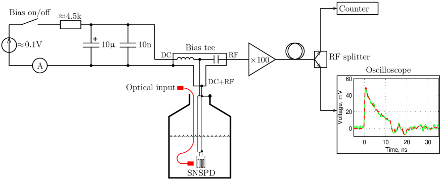
We performed our tests on an SNSPD of a fairly standard configuration, which has been characterized in previous publications Akhlaghi and Majedi (2008); Orgiazzi and Majedi (2009); Yan et al. (2009). The SNSPD chip was manufactured by Scontel, Moscow, and consists of a thick, wide NbN nanowire on sapphire substrate, laid out in a meander pattern with 60% filling ratio. The chip is packaged and installed in a long dipstick assembly (see Ref. Orgiazzi and Majedi (2009) for details), lowered into a Dewar flask. During detector operation, the chip is immersed into liquid helium at . It is optically accessible through a single-mode fibre. The chip is connected to a room-temperature bias tee and wideband radio-frequency (RF) amplifier via a coaxial cable (Fig. 1). A battery-powered current source biases the superconducting nanowire with which is of its critical current (this value provides the highest ratio of photon detection probability at to dark count rate, for this particular SNSPD sample). The signal from the output of the RF amplifier is split to a single-shot oscilloscope (Tektronix DSA 71604) and a counter (Stanford Research Systems SR400). Detection efficiency for single photons at was and the dark count rate was , which is a typical performance for this SNSPD model (higher detection efficiency can be obtained at the expense of much higher dark count rate; while this SNSPD was not optimised for high detection efficiency, the effects we have observed should qualitatively be the same as with efficiency-optimised designs Rosfjord et al. (2006)). The detector sensitivity was polarization-dependent; in all experiments in this paper polarization was aligned to maximize the detection efficiency, using a fiber polarization controller.
One aspect of detector operation is how the analog pulse produced by a transient hotspot (see inset in Fig. 1) is converted into a detection event and assigned a particular timing. The analog pulse is well-defined, its magnitude and shape being nearly constant from one photon detection to another. Therefore almost any discriminator design would work for single-photon detection, and its implementation details (bandwidth, hysteresis, whether it is a threshold discriminator or a constant-fraction discriminator, etc.) are often omitted in the literature on SNSPDs. However, as previously discussed for APDs Yuan et al. (2010); Lydersen et al. (2010c), these details become more important for demonstration of detector control by bright light. We assume in this study that the analog pulse is sensed by a high-speed voltage comparator, and the detection event timing is registered by pulse’s leading edge crossing a pre-set comparator threshold. Indeed this is how our SR400 counter operates: it has an adjustable threshold set with resolution. In our setup, the counter works correctly (registering one count per one single-photon analog pulse) in a wide range of threshold settings, to . A detail not mentioned in the literature is what threshold level the comparator should be set at, within this working range. While the setting may not affect normal detector operation, only a part of this voltage range is reachable under bright-light control described in the following section.
Another interesting aspect of detector operation is latching. In single-photon detection regime, the hotspot after formation shrinks quickly and the nanowire returns to the superconducting state Yang et al. (2007). However the detector also has a stable latched state, when a larger self-heating hotspot persists indefinitely, at a steady current which is a fraction of , and a large voltage across the SNSPD. The detector is blind to single photons and does not produce dark counts in this regime. A properly designed SNSPD does not enter the latched state after a single-photon detection Yang et al. (2007); Annunziata et al. (2010). However it can still latch after an electromagnetic interference (which in our experiment was easily caused by switching on and off lights and other mains-powered electrical equipment in the same building). Latching also occurs after a brief bright illumination: as little as , long single light pulse at reliably latches the device. Increasing the bias current very close to also leads to latching. The only way to return the detector from the latched state into the normal regime is to temporarily reduce below . In our experiment, and supposedly in most other experiments reported in the literature, this was performed manually.
III Detector control in latched state
III.1 Physics
In the latched state, the Joule heat generated in the normally-conductive fraction of the nanowire exactly balances the cooling. The length of the normally-conductive fraction changes with the voltage applied across the SNSPD. We investigated this by replacing the battery-powered bias source with an external bias source consisting of a constant-current source limited at a certain maximum voltage. Since the SNSPD enters and maintains latching at a current lower than the normal bias current, this bias source automatically turns into a voltage source once the device latches. In our experiment, was roughly regardless of the voltage across the device, up to (we did not apply higher voltages to reduce the chance of electrical breakdown). At , the nanowire resistance was thus . Above the superconducting transition temperature the resistance of the entire device is approximately constant, and is Yan et al. (2009). Therefore we concluded that slightly over half its length was normally-conductive at . During the experiment, would randomly assume a value in the to range, which could correspond to the normally-conductive region shifting and “locking” to the local variations of nanowire thermal characteristics along its length.
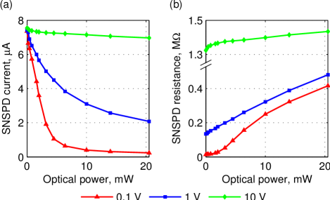
Next, we investigated what happened when bright continuous-wave (CW) light was applied in the latched state. Under illumination, current through the device dropped, with a different sensitivity at different voltages (Fig. 2(a)). When recalculated into device resistance (Fig. 2(b)), we see that at low source voltages the resistance increased by about the same amount (– per ), while at the increase was smaller (). Note that depending on optical coupling, illumination may be unevenly distributed along the nanowire.
Implementation and maximum voltage of the bias source is yet another detail that varies between setups and is rarely specified in the literature. In our detector it is implemented as a voltage source in series with resistor (see Fig. 1), with both voltage and resistance being trimmable in a small range to set precise in the normal (non-latched) regime. When the SNSPD resistance is zero, this bias circuit acts as a current source. However, in the latched state the SNSPD resistance becomes larger than the circuit output impedance, thus it acts as a voltage source. Measurements done with this battery-powered bias circuit closely match the curve in Fig. 2.
III.2 Exploit
The eavesdropper Eve can latch the device by applying sufficient illumination at the SNSPD, for instance a single , long light pulse at . The latching causes a number of random detection events, depending on the discriminator setting and optical power of the latching pulse. However, for intense illumination, it is possible for Eve to latch the device with only a few random events (for instance using optical power for some at discriminator threshold). Also note that Eve only have to latch the device once.
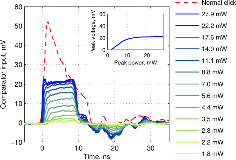
In the latched state, the SNSPD is insensitive to single photons and produces no dark counts (similarly to blinding of APDs Makarov (2009); Lydersen et al. (2010a)). However, the nanowire’s response to bright CW illumination detailed in Sec. III.1 also holds on a nanosecond scale for bright pulses, and can be used to produce an electrical pulse after the RF amplifier and splitter (Fig. 3) 222The measurement in Figures 3 and 4 was taken some days apart from the measurement in Fig. 2. Unfortunately it seems we had an optical and/or polarization alignment problem during the former: the detector is times less sensitive in Figures 3 and 4 than in the rest of the paper, with its behaviour being otherwise consistent except for the scale factor of on the optical power.. The response is caused by a larger piece of the nanowire becoming normally conductive during the bright illumination, therefore causing an abrupt change in the resistance, just as a single photon causes an abrupt change in the resistance in the normal operating regime. Note that the electrical response to a bright trigger pulse saturates at when optical power is applied, because at this power the current through the nanowire is reduced to almost zero.
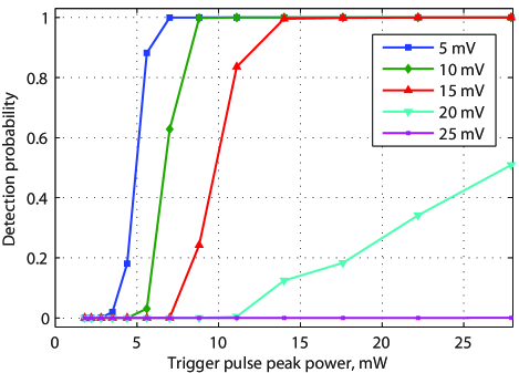
Since this analog electrical pulse is sensed by a comparator, the detector has a highly superlinear detection probability of bright pulses Lydersen et al. (2011b). By simulating an ideal bandwidth-limited comparator on recorded wideband long oscilloscope traces, we find that the detection probability would depend strongly on the comparator threshold (Fig. 4). With the comparator threshold in the 5–20 range, the detection probability is highly superlinear and increases quickly from negligible to a substantial value for a increase in the optical power. A sufficient condition for a detector control attack is a large ratio of detection probabilities over a change in the trigger pulse power Lydersen et al. (2010a, 2011b) (or change in the trigger pulse power for distributed-phase-reference protocols Lydersen et al. (2011a)). Then Eve can intercept the quantum states from Alice, and resend bright trigger pulses corresponding to her detection to Bob Lydersen et al. (2010a, 2011b). If Eve used a measurement basis not matching Bob’s, she wants her pulse to remain undetected. Indeed when the pulse is measured by Bob in a different basis, it will be split to both detectors, corresponding to reduction in its power, and almost never cause a click. Due to the large difference in detection probability for change in the trigger pulse amplitude, a detector control attack would cause negligible errors and not expose eavesdropping, for the comparator threshold settings . Above the trigger pulses stop causing clicks at all, and this attack method no longer works. However, it may be possible to reach higher threshold settings using a different attack method described in the next section.
IV Detector control via deadtime extension
IV.1 Physics
In this section we consider a non-latched, single-photon sensitive normally operating detector. The attack is based on detector’s ability to form a hotspot in response to bright light when the current through the SNSPD is low. In addition, the hotspot formation probability at a low current is strongly superlinear. It is well-known that at relatively low values of the bias current , multiphoton processes dominate the detector sensitivity Verevkin et al. (2002); Akhlaghi and Majedi (2009); Lydersen et al. (2011b). Here we demonstrate that this effect becomes extreme during the normal recovery time after a photon detection.
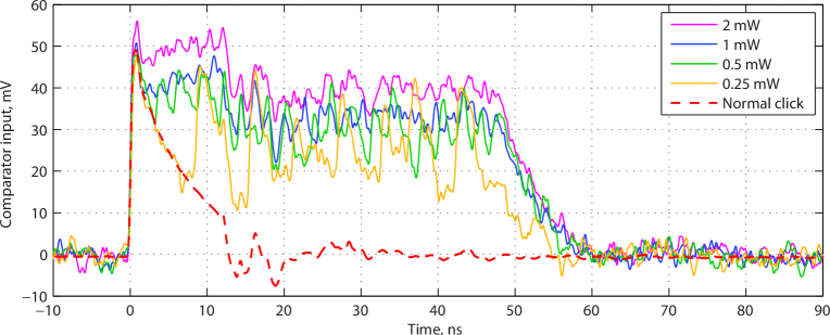
In normal detector operation, after the hotspot formation, drops to a fraction of Yang et al. (2007). Then, exponentially recovers to at a slow rate, owing to a relatively large kinetic inductance of the superconducting nanowire (see dashed trace in Fig. 5). During the initial part of this recovery, the SNSPD remains insensitive to single photons, but it can react to a bright illumination by forming another hotspot, with a higher illumination power being able to form a hotspot earlier in the recovery. This is illustrated in Fig. 5, which shows electrical response to a long bright pulse. At pulse power, the single-shot trace clearly shows that the SNSPD forms a hotspot on average every . At , the period reduces to . At higher optical powers separate hotspot formations are no longer distinguishable, but the whole electrical pulse gets higher, indicating a lower average current through the nanowire during the optical pulse. Thus, during a sufficiently bright optical pulse, the electrical signal will stay above the comparator threshold. This allows Eve to extend the detector deadtime after the first photon detection, up to with this detector setup, without causing latching.
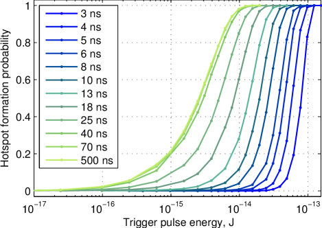
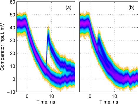
We further quantify the hotspot formation probability during the recovery, by applying a FWHM trigger pulse after the closing edge of the , pulse. (The recovery after the bright pulse should be similar to the recovery after a single-photon detection, however we focus on the former for reasons that will become apparent in the next subsection.) As far as we can see, response to this trigger pulse is probabilistic and binary: the hotspot either forms, or it does not (Fig. 6). In the former case the recovery resets and starts anew from a certain current value, in the latter case the recovery continues undisturbed. The probability that the trigger pulse causes a hotspot is plotted in Fig. 7. The measurement shows that the detection probability is reduced for at least . It also shows that the detector is highly superlinear in at least the first . During this time, a hotspot can be formed with unity probability using a sufficiently high-energy trigger pulse (), while the same trigger pulse attenuated by (i.e., 100 times lower pulse energy) is very unlikely to cause a hotspot formation.
IV.2 Exploit
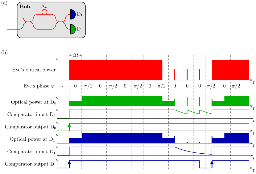
Extendability of SNSPD’s deadtime can be exploited in the earlier described attack Makarov (2009) on the Bennett-Brassard 1984 (BB84) and similar protocols. We remark that the superlinearity is not required for this attack, but is helpful and makes it easier. Here we propose a version of this attack for differential-phase-shift QKD (DPS-QKD) systems Nambu et al. (2004); Takesue et al. (2007). We explain the key component of the attack: how Eve can control Bob’s SNSPDs in the DPS-QKD system. Bob consists of an unbalanced Mach-Zehnder interferometer, and two detectors and (Fig. 8(a)). We assume that a properly implemented Bob will not accept clicks from both detectors for the duration of recovery after a click in one of the detectors, in order to avoid the detector deadtime and efficiency mismatch loopholes Weier et al. (2011); Makarov et al. (2006). As illustrated above, the expected recovery is long. Eve begins by applying to both detectors a laser pulse longer than the recovery time (Fig. 8(b)), with phase changing in steps along the pulse such that its power splits equally to the two detectors. This pulse produces a double click at the beginning, which however can be timed to fall in between the bit slots and be discarded by Bob (the extra clicks may affect routines that adjust timing of Bob’s acceptance windows, but note that attacks on such calibration routines are also possible Jain et al. (2011)). Immediately after this long pulse, Eve applies a sequence of short pulses. Their phases are chosen to steer them primarily to one of the two detectors (similarly to Makarov and Skaar (2008); Lydersen et al. (2011a)) and form hotspots in that detector only, keeping the comparator input voltage above the threshold. In the other detector, the voltage is allowed to fall below the comparator threshold. Then a pulse is applied and causes a click only in the detector that has recovered. Eve can end her control diagram here, or repeat the long pulse (as shown in Fig. 8(b)) and then make another controlled click. The total length of such chained control diagram producing several controlled clicks is limited by low-frequency cutoff of the RF components, and in the case of our setup can be up to . We remark that the short-pulsed parts of the diagram could in principle be replaced by a single phase-modulated long pulse, however short pulses may be easier to steer between Bob’s detectors in case of sub-nanosecond used in the modern DPS-QKD systems Takesue et al. (2007).
Interferometers used for DPS-QKD are of a sufficiently good quality to allow Eve an extinction ratio of at least when routing her short pulses between the two Bob’s detectors Takesue et al. (2007). Examination of the recovery traces in Fig. 6 and hotspot formation probabilities in Fig. 7 suggests that the above control diagram will work. It should allow Eve to make clicks in Bob deterministically, or close to deterministically, in a wide range of comparator threshold voltages and , even for Takesue et al. (2007) or/and a threshold voltage above . Eve should be able to vary the number of short pulses during the recovery to suit these system parameters, and still induce clicks in the correct detector most of the time.
While we did not have access to a complete DPS-QKD system to fully verify this Bob control method, we tested it experimentally by reproducing the expected power diagrams (optical power at and in Fig. 8(b)) at the single detector. We used , and threshold setting of at the SR400 counter. We applied to the detector peak power, long optical pulse, followed by FWHM short optical pulses of varying energy. Measurement of the click probability while varying the short pulse energy showed that nearly perfect detector control ( click probability in the wrong detector) would be achievable if Bob’s interferometer in the DPS-QKD system had a reasonable extinction ratio, and good control ( click probability in the wrong detector) would be possible at a very poor extinction ratio. The extinction ratio of Bob’s interferometer determines how well Eve can suppress her short pulses from reaching the wrong detector, while making the target detector click with nearly unity probability. Jitter of the controllable click caused by the short pulse in the target detector was FWHM, while that of the double click caused by the long pulse’s leading edge was FWHM.
One can notice that Eve would need to know Bob’s detector parameters rather precisely to execute this attack. In modern cryptography, according to Kerckhoffs’ principle Kerckhoffs (1883), properties of equipment are assumed to be fully known to Eve. In practice, to learn the detector parameters, Eve might at first try to attack intermittently a few bits at a time (which would not raise the error rate noticeably) while varying her attack parameters, and watch the public discussion between Alice and Bob Makarov and Hjelme (2005). One can also notice that Eve’s intercept-and-resend equipment would introduce an insertion delay of at least some tens of . However, photon’s time-of-flight is not authenticated in today’s implementations of QKD, and is not a part of the practical QKD protocols. Furthermore, in a fiber-optic line, Eve can easily cancel this insertion delay by shortcutting a part of the line between her intercept and resend units with a line-of-sight radio-frequency classical link Makarov and Hjelme (2005); Gerhardt et al. (2011).
V Discussion and conclusion
The experimental results show that the control of this SNSPD is nearly perfect. Therefore, if this SNSPD were used in a QKD system, an eavesdropper could use bright illumination to capture the full raw and secret key, while introducing negligible errors. Installation of the eavesdropper is fully reversible: The detector survived the bright illumination with no signs of damage or deterioration ††footnotemark: .
While the SNSPD is based on different physics than the APD single-photon detector, the similarity in how they can be controlled is startling. Latching the SNSPD using bright illumination can be considered as permanently blinding it, without the need for additional illumination to keep it blind. In the latched/blind state, the SNSPD exhibits the same superlinear response to bright trigger pulses as a blind APD. Likewise, controlling the SNSPD using deadtime extension is nearly identical to controlling the APD using deadtime extension: the only difference is that for this SNSPD the low-frequency cut-off of the RF components (and on a longer time scale the latching phenomenon) limits how long the deadtime can be extended.
Countermeasures against bright illumination attacks have been discussed extensively Makarov (2009); Lydersen et al. (2010a, b); Yuan et al. (2010); Lydersen et al. (2010c, 2011c); Gerhardt et al. (2011); Yuan et al. (2011); Lydersen et al. (2011d), and the conclusions are equally applicable to SNSPDs. The difference between public-key cryptography and QKD is that for the latter there exist security proofs. However, when the security is proved for systems with imperfections, models are used for the devices in the implementations. Even if this experiment is only performed on one device, the results show that the response deviates considerably from the models in the simple security proofs that are usually employed Lo and Chau (1999); Shor and Preskill (2000); Gottesman et al. (2004). There are more advanced security proofs that could allow such a response under certain conditions Marøy et al. (2010); Lydersen et al. (2011b), but this would require discarding large amounts of the raw key to remove Eve’s knowledge about the final key. For gated APD-based detectors, there is a proposal to bound the detector parameters by including a calibrated light source inside Bob, randomly testing, and thereby guaranteeing the single-photon sensitivity at random times Lydersen et al. (2011c). Another approach suggests to move detectors outside the secure devices and thus outside the security proof Lo et al. ; Braunstein and Pirandola .
If one only wants to avoid these specific attacks, proposals for APD-based detectors Makarov (2009); Lydersen et al. (2010a, b); Yuan et al. (2010); Lydersen et al. (2010c, 2011c); Gerhardt et al. (2011); Yuan et al. (2011); Lydersen et al. (2011d) should be equally efficient on SNSPDs, for instance an optical power meter at the entrance of Bob. In an installed QKD system, latching should be avoided either by an automated reset, or by including a shunt resistor in parallel with the nanowire 333R. Hadfield, private communication (2011)., but this does not guarantee that latching is precluded for all types of external input. Developing such specific countermeasures effective against specific, known attacks is less than satisfactory, because this introduces an unproven extra assumption into the QKD security model that the countermeasure also eliminates all unknown attacks exploiting the same loophole. Meanwhile, the difference between the device and its model in the QKD security proof remains. This approach would downgrade the level of QKD security model to that of public-key cryptography, which also includes unproven assumptions (of computational complexity).
As mentioned in the introduction, SNSPDs are still in their infancy, and therefore our findings might not apply to other detector designs. However, our findings clearly demonstrate that unless detector control is specially considered during design, SNSPDs may be controllable using bright illumination, just as their APD-based cousins. Furthermore, it could be possible to design the SNSPDs to be compliant with security proofs for QKD. The early stage of SNSPD technology is an excellent opportunity to avoid detector control vulnerability for future generations of SNSPDs. Designing hack-proof detectors will be crucial for the success of QKD.
Acknowledgements.
We thank A. Korneev, R. Hadfield and V. Burenkov for useful discussions. This work was supported by the Research Council of Norway (grant no. 180439/V30), Ontario Center of Excellence (OCE) and National Research Council of Canada (NSERC). L.L. and V.M. thank Institute for Quantum Computing for travel support during their visit to Waterloo.References
- Bennett and Brassard (1984) C. H. Bennett and G. Brassard, in Proceedings of IEEE International Conference on Computers, Systems, and Signal Processing (IEEE Press, New York, Bangalore, India, 1984) pp. 175–179.
- Ekert (1991) A. K. Ekert, Phys. Rev. Lett. 67, 661 (1991).
- Gisin et al. (2002) N. Gisin, G. Ribordy, W. Tittel, and H. Zbinden, Rev. Mod. Phys. 74, 145 (2002).
- Scarani et al. (2009) V. Scarani, H. Bechmann-Pasquinucci, N. J. Cerf, M. Dušek, N. Lütkenhaus, and M. Peev, Rev. Mod. Phys. 81, 1301 (2009).
- Lo and Chau (1999) H.-K. Lo and H. F. Chau, Science 283, 2050 (1999).
- Shor and Preskill (2000) P. W. Shor and J. Preskill, Phys. Rev. Lett. 85, 441 (2000).
- Mayers (1996) D. Mayers, in Proceedings of Crypto’96, Vol. 1109, edited by N. Koblitz (Springer, New York, 1996) pp. 343–357.
- Inamori et al. (2007) H. Inamori, N. Lütkenhaus, and D. Mayers, Eur. Phys. J. D 41, 599 (2007).
- Koashi and Preskill (2003) M. Koashi and J. Preskill, Phys. Rev. Lett. 90, 057902 (2003).
- Gottesman et al. (2004) D. Gottesman, H.-K. Lo, N. Lütkenhaus, and J. Preskill, Quant. Inf. Comp. 4, 325 (2004).
- Lo and Preskill (2007) H.-K. Lo and J. Preskill, Quant. Inf. Comp. 7, 431 (2007).
- Zhao et al. (2008a) Y. Zhao, B. Qi, and H.-K. Lo, Phys. Rev. A 77, 052327 (2008a).
- Fung et al. (2009) C.-H. F. Fung, K. Tamaki, B. Qi, H.-K. Lo, and X. Ma, Quant. Inf. Comp. 9, 131 (2009).
- Lydersen and Skaar (2010) L. Lydersen and J. Skaar, Quant. Inf. Comp. 10, 60 (2010).
- Marøy et al. (2010) Ø. Marøy, L. Lydersen, and J. Skaar, Phys. Rev. A 82, 032337 (2010).
- Vakhitov et al. (2001) A. Vakhitov, V. Makarov, and D. R. Hjelme, J. Mod. Opt. 48, 2023 (2001).
- Gisin et al. (2006) N. Gisin, S. Fasel, B. Kraus, H. Zbinden, and G. Ribordy, Phys. Rev. A 73, 022320 (2006).
- Makarov et al. (2006) V. Makarov, A. Anisimov, and J. Skaar, Phys. Rev. A 74, 022313 (2006), erratum ibid. 78, 019905 (2008).
- Qi et al. (2007) B. Qi, C.-H. F. Fung, H.-K. Lo, and X. Ma, Quant. Inf. Comp. 7, 73 (2007).
- Zhao et al. (2008b) Y. Zhao, C.-H. F. Fung, B. Qi, C. Chen, and H.-K. Lo, Phys. Rev. A 78, 042333 (2008b).
- Lamas-Linares and Kurtsiefer (2007) A. Lamas-Linares and C. Kurtsiefer, Opt. Express 15, 9388 (2007).
- Fung et al. (2007) C.-H. F. Fung, B. Qi, K. Tamaki, and H.-K. Lo, Phys. Rev. A 75, 032314 (2007).
- Xu et al. (2010) F. Xu, B. Qi, and H.-K. Lo, New J. Phys. 12, 113026 (2010).
- Makarov (2009) V. Makarov, New J. Phys. 11, 065003 (2009).
- Lydersen et al. (2010a) L. Lydersen, C. Wiechers, C. Wittmann, D. Elser, J. Skaar, and V. Makarov, Nat. Photonics 4, 686 (2010a).
- Jain et al. (2011) N. Jain, C. Wittmann, L. Lydersen, C. Wiechers, D. Elser, C. Marquardt, V. Makarov, and G. Leuchs, Phys. Rev. Lett. 107, 110501 (2011).
- Sun et al. (2011) S.-H. Sun, M.-S. Jiang, and L.-M. Liang, Phys. Rev. A 83, 062331 (2011).
- Gerhardt et al. (2011) I. Gerhardt, Q. Liu, A. Lamas-Linares, J. Skaar, C. Kurtsiefer, and V. Makarov, Nat. Commun. 2, 349 (2011).
- Weier et al. (2011) H. Weier, H. Krauss, M. Rau, M. Fürst, S. Nauerth, and H. Weinfurter, New J. Phys. 13, 073024 (2011).
- Lydersen et al. (2011a) L. Lydersen, J. Skaar, and V. Makarov, J. Mod. Opt. 58, 680 (2011a).
- Wiechers et al. (2011) C. Wiechers, L. Lydersen, C. Wittmann, D. Elser, J. Skaar, C. Marquardt, V. Makarov, and G. Leuchs, New J. Phys. 13, 013043 (2011).
- Sauge et al. (2011) S. Sauge, L. Lydersen, A. Anisimov, J. Skaar, and V. Makarov, Opt. Express 19, 23590 (2011).
- Lydersen et al. (2010b) L. Lydersen, C. Wiechers, C. Wittmann, D. Elser, J. Skaar, and V. Makarov, Opt. Express 18, 27938 (2010b).
- Lydersen et al. (2011b) L. Lydersen, N. Jain, C. Wittmann, Ø. Marøy, J. Skaar, C. Marquardt, V. Makarov, and G. Leuchs, Phys. Rev. A 84, 032320 (2011b).
- Makarov and Hjelme (2005) V. Makarov and D. R. Hjelme, J. Mod. Opt. 52, 691 (2005).
- Hadfield et al. (2006) R. H. Hadfield, J. L. Habif, J. Schlafer, R. E. Schwall, and S. W. Nam, Appl. Phys. Lett. 89, 241129 (2006).
- Takesue et al. (2007) H. Takesue, S. W. Nam, Q. Zhang, R. H. Hadfield, T. Honjo, K. Tamaki, and Y. Yamamoto, Nat. Photonics 1, 343 (2007).
- Stucki et al. (2009) D. Stucki, N. Walenta, F. Vannel, R. T. Thew, N. Gisin, H. Zbinden, S. Gray, C. R. Towery, and S. Ten, New J. Phys. 11, 075003 (2009).
- Rosenberg et al. (2009) D. Rosenberg, C. G. Peterson, J. W. Harrington, P. R. Rice, N. Dallmann, K. T. Tyagi, K. P. McCabe, S. Nam, B. Baek, R. H. Hadfield, R. J. Hughes, and J. E. Nordholt, New J. Phys. 11, 045009 (2009).
- Liu et al. (2010) Y. Liu, T.-Y. Chen, J. Wang, W.-Q. Cai, X. Wan, L.-K. Chen, J.-H. Wang, S.-B. Liu, H. Liang, L. Yang, C.-Z. Peng, K. Chen, Z.-B. Chen, and J.-W. Pan, Opt. Express 18, 8587 (2010).
- Note (1) Testing was restricted to one sample owing to difficulty of gaining access to more samples. One reason for this was that high-power illumination was initially assumed to be potentially lethal to the devices. However, the sample we tested survived undamaged. In fact, the measurement in Sec. III.1 suggests that the maximum temperature of the nanowire under , continuous-wave illumination stayed relatively low, because only a part of the nanowire rose above the superconducting transition temperature of .
- Akhlaghi and Majedi (2008) M. K. Akhlaghi and A. H. Majedi, in IEEE Lasers and Electro-Optics Society, 2008. LEOS 2008. 21st Annual Meeting of the (2008) pp. 234–235.
- Orgiazzi and Majedi (2009) J.-L. F.-X. Orgiazzi and A. H. Majedi, IEEE Trans. Appl. Supercond. 19, 341 (2009).
- Yan et al. (2009) Z. Yan, M. K. Akhlaghi, J. L. Orgiazzi, and A. H. Majedi, J. Mod. Opt. 56, 380 (2009).
- Rosfjord et al. (2006) K. M. Rosfjord, J. K. W. Yang, E. A. Dauler, A. J. Kerman, V. Anant, B. M. Voronov, G. N. Gol’tsman, and K. K. Berggren, Opt. Express 14, 527 (2006).
- Yuan et al. (2010) Z. L. Yuan, J. F. Dynes, and A. J. Shields, Nat. Photonics 4, 800 (2010).
- Lydersen et al. (2010c) L. Lydersen, C. Wiechers, C. Wittmann, D. Elser, J. Skaar, and V. Makarov, Nat. Photonics 4, 801 (2010c).
- Yang et al. (2007) J. K. W. Yang, A. J. Kerman, E. A. Dauler, V. Anant, K. M. Rosfjord, and K. K. Berggren, IEEE Trans. Appl. Supercond. 17, 581 (2007).
- Annunziata et al. (2010) A. J. Annunziata, O. Quaranta, D. F. Santavicca, A. Casaburi, L. Frunzio, M. Ejrnaes, M. J. Rooks, R. Cristiano, S. Pagano, A. Frydman, and D. E. Prober, J. Appl. Phys. 108, 084507 (2010).
- Note (2) The measurement in Figures 3 and 4 was taken some days apart from the measurement in Fig. 2. Unfortunately it seems we had an optical and/or polarization alignment problem during the former: the detector is times less sensitive in Figures 3 and 4 than in the rest of the paper, with its behaviour being otherwise consistent except for the scale factor of on the optical power.
- Verevkin et al. (2002) A. Verevkin, J. Zhang, R. Sobolewski, A. Lipatov, O. Okunev, G. Chulkova, A. Korneev, K. Smirnov, G. N. Gol’tsman, and A. Semenov, Appl. Phys. Lett. 80, 4687 (2002).
- Akhlaghi and Majedi (2009) M. K. Akhlaghi and A. H. Majedi, IEEE Trans. Appl. Supercond. 19, 361 (2009).
- Nambu et al. (2004) Y. Nambu, T. Hatanaka, and K. Nakamura, Jpn. J. Appl. Phys. 43, L1109 (2004).
- Makarov and Skaar (2008) V. Makarov and J. Skaar, Quant. Inf. Comp. 8, 622 (2008).
- Kerckhoffs (1883) A. Kerckhoffs, J. des Sciences Militaires IX, 5 (1883).
- Lydersen et al. (2011c) L. Lydersen, V. Makarov, and J. Skaar, Phys. Rev. A 83, 032306 (2011c).
- Yuan et al. (2011) Z. L. Yuan, J. F. Dynes, and A. J. Shields, Appl. Phys. Lett. 98, 231104 (2011).
- Lydersen et al. (2011d) L. Lydersen, V. Makarov, and J. Skaar, Appl. Phys. Lett. 99, 196101 (2011d).
- (59) H.-K. Lo, M. Curty, and B. Qi, arXiv:1109.1473 [quant-ph] .
- (60) S. L. Braunstein and S. Pirandola, arXiv:1109.2330 [quant-ph] .
- Note (3) R. Hadfield, private communication (2011).