Model-free control of non-minimum phase systems and switched systems
Loïc MICHEL
GRÉI - Département de génie électrique et génie informatique
Université du Québec à Trois-Rivières
C.P. 500, Trois-Rivières, G9A 5H7, Canada, QC
Abstract
This brief111This work is distributed under CC license http://creativecommons.org/licenses/by-nc-sa/3.0/ presents a simple derivation of the standard model-free control for the non-minimum phase systems. The robustness of the proposed method is studied in simulation considering the case of switched systems.
1 Introduction
The model-free control methodology, originally proposed by [1], has been widely successfully applied to many mechanical and electrical processes. The model-free control provides good performances in disturbances rejection and an efficient robustness to the process internal changes. The control of non-minimum phase systems has been deeply studied and successful methods have been proposed (e.g. [2] [3] [4] [5] [6] [7] [8] [9]). Since the model-free control can not a priori stabilize a non-minimum phase system [1], we propose a possible derivation of the original model-free control law, dedicated to the control of non-minimum phase systems. The dynamic performances are especially tested in the case of switched systems.
The paper is structured as follows. Section II presents an overview of the model-free control methodology including its advantages in comparison with classical methodologies. Section III discusses the application of the modified model-free control, called NM-model-free control, for non-minimum phase systems. Some concluding remarks may be found in Section IV.
2 Model-free control: a brief overview
2.1 General principles
2.1.1 The ultra-local model
We only assume that the plant behavior is well approximated in its operational range by a system of ordinary differential equations, which might be highly nonlinear and time-varying.***See [1, 10] for further details. The system, which is SISO, may be therefore described by the input-output equation
| (1) |
where
-
•
and are the input and output variables,
-
•
, which might be unknown, is assumed to be a sufficiently smooth function of its arguments.
Assume that for some integer , , . From the implicit function theorem we may write locally
By setting we obtain the ultra-local model.
Definition 2.1
[1] If and are respectively the variables of input and output of a system to be controlled, then this system admits the ultra-local model defined by:
| (2) |
where
-
•
is a non-physical constant parameter, such that and are of the same magnitude;
-
•
the numerical value of , which contains the whole “structural information”, is determined thanks to the knowledge of , , and of the estimate of the derivative .
In all the numerous known examples it was possible to set or .
2.1.2 Numerical value of
Let us emphasize that one only needs to give an approximate numerical value to . It would be meaningless to refer to a precise value of this parameter.
2.2 Intelligent PI controllers
2.2.1 Generalities
Definition 2.2
[1] we close the loop via the intelligent PI controller, or i-PI controller,
| (3) |
where
- •
-
•
is the tracking error;
-
•
is of the form . , are the usual tuning gains.
Equation (3) is called model-free control law or model-free law.
The i-PI controller 3 is compensating the poorly known term . Controlling the system therefore boils down to the control of a precise and elementary pure integrator. The tuning of the gains and becomes therefore quite straightforward.
2.2.2 Classic controllers
See [13] for a comparison with classic PI controllers.
2.3 A first academic example: a stable monovariable linear system
2.3.1 A classic PID controller
2.3.2 i-PI.
We are employing and the i-PI controller
where
-
•
,
-
•
is a reference trajectory,
-
•
,
-
•
is an usual PI controller.
2.3.3 Numerical simulations
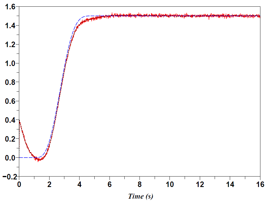
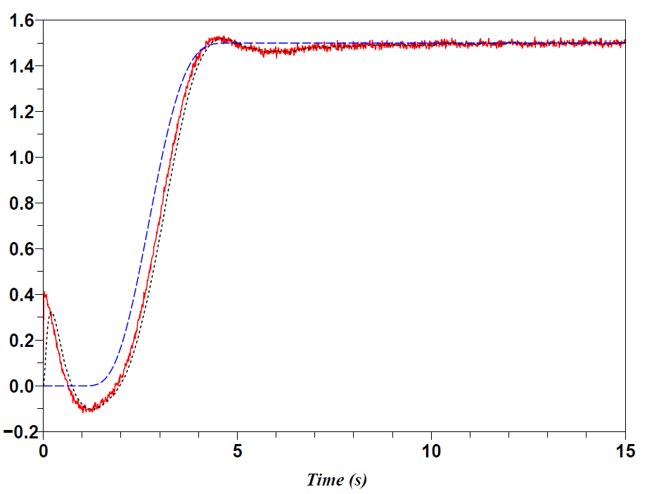
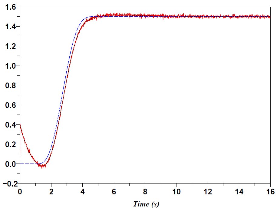
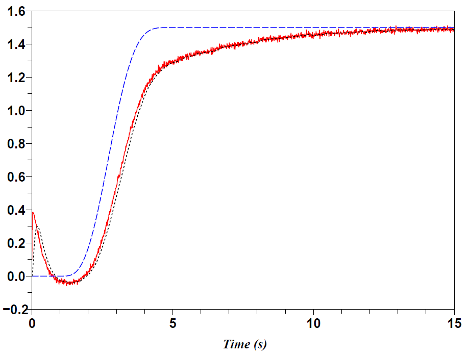
Figure 1(a) shows that the i-PI controller behaves only slightly better than the classic PID controller (Fig. 1(b)). When taking into account on the other hand the ageing process and some fault accommodation there is a dramatic change of situation: Figure 1(c) indicates a clear cut superiority of our i-PI controller if the ageing process corresponds to a shift of the pole from to , and if the previous graphical identification is not repeated (Fig. 1(d)).
2.3.4 Some consequences
-
•
It might be useless to introduce delay systems of the type
(5) for tuning classic PID controllers, as often done today in spite of the quite involved identification procedure.
-
•
This example demonstrates also that the usual mathematical criteria for robust control become to a large irrelevant.
-
•
As also shown by this example some fault accommodation may also be achieved without having recourse to a general theory of diagnosis.


3 Control of non-minimum phase systems
We explain in this section, how to derive the model-free control law (3) in order to stabilize and guarantee certain performances for non-minimum phase systems. We will show that the proposed control law is also robust to disturbances and switched models.
3.1 Discrete model-free control law for non-minimum phase systems
Firstly, consider the discretized model-free control law, which is typically used for a digital implementation.
Definition 3.1
[15] For any discrete moment , one defines the discrete controller i-PI.
| (6) |
where
-
is the output reference trajectory;
-
is the tracking error;
-
is a usual corrector PI where , are the usual tuning gains.
The discrete intelligent controller is also called discrete model-free control law or discrete model-free law.
Non-minimum phase systems are characterized by negative zero(s). Such zero can be approximated by a delay since using a Taylor expansion. To compensate the effect of the delay, that may destabilize the control, we take the derivative of the output instead of the output to create the measurement feedback. This way allows to anticipate the variations of and finally cancel the disturbances associated to the presence of the delay.
We define consequently the i*-PI controller for non-minimum phase systems.
Definition 3.2
For any discrete moment , one defines the discrete controller i*-PI for non-minimum phase systems. and are real coefficients.
| (7) |
where
-
is the output reference trajectory;
-
is the tracking error;
-
is called a gain function and is either a pure gain or an integrator†††Depending on the application, a pure gain can be enough to ensure good tracking performances..
The discrete intelligent controller is also called discrete NM-model-free control law or discrete NM-model-free law.
Practically, simulations show that is sufficient‡‡‡The possibility of reducing will be studied in a future work. to ensure at least the stability of the model-free control closed-loop. Therefore, (7) is written :
| (8) |
For the following applications, we choose the gain function as an integrator, with a constant, such that :
| (9) |
3.2 Applications
Consider the systems , , and , which are minimum and non-minimum phase systems, and which are described respectively by the state-space representations :
| (10) |
| (11) |
| (12) |
| (13) |
The unitary step response of these systems is presented Fig. 2.

The following figures present some preliminary examples of the application of the i*-PI control. Figure 3 presents the tracking of an exponential reference for the system (with a focus on the beginning of the transient). Figures 5 and 5 show the response of the controlled system when respectively switches to and with the addition of a sinusoidal disturbance on the variable . Figures 7 and 7 present the control of switched systems; in particular the commutation from a non-minimum phase system to a minimum phase system. Figures 9 and 9 present the tracking of a sinusoidal reference when systems switch. The case where switches to has been already studied in [16]. We investigated the application of the model-free control in a microgrid environment under load / transfer function changes. These changes imply substantial modifications of the controlled models.


4 Concluding remarks
We presented some simulation results that confirm the fact that the NM-model-free control or i*-PI controller, designed for the control of non-minimum phase systems, ensure good tracking performances. We evaluated the performances in presence of disturbances and in the case of switched systems. In particular, the NM-model-free control is able a priori to control both minimum and non-minimum-phase systems. The proposed control law seems to have the same properties than the original model-free control [1] for which its performances have been successfully proved in simulation when controlling switched systems (e.g. [16]). Further work will concern the study of the stability of the NM-model-free control method and its applications to networked systems.
References
- [1] M. Fliess and C. Join, “Commande sans modèle et commande à modèle restreint“, e-STA, vol. 5 (n∘ 4), pp. 1-23, 2008 (available at http://hal.inria.fr/inria-00288107/en/).
- [2] K. J. Astrom, “Direct methods for nonminimum phase systems“, in 19th IEEE Conference on Decision and Control including the Symposium on Adaptive Processes, vol.19, pp.611-615, Dec. 1980.
- [3] E.-W. Bai and S. Dasgupta, “A minimal k-step delay controller for robust tracking of non-minimum phase systems“, in Proceedings of the 33rd IEEE Conference on Decision and Control, vol.1, pp.12-17, Dec 1994.
- [4] A. Isidori, “A tool for semi-global stabilization of uncertain non-minimum-phase nonlinear systems via output feedback“, IEEE Transactions on Automatic Control, vol.45, no.10, pp. 1817-1827, Oct. 2000.
- [5] N. Wang, W. Xu and F. Chen, “Adaptive global output feedback stabilisation of some non-minimum phase nonlinear uncertain systems“, IET Control Theory & Applications, vol.2, no.2, pp.117-125, Feb. 2008.
- [6] M. Benosman, F. Liao, K.-Y. Lum and J. Liang Wang, “Nonlinear Control Allocation for Non-Minimum Phase Systems“, IEEE Transactions on Control Systems Technology, vol.17, no.2, pp.394-404, Mar. 2009.
- [7] R. Gurumoorthy and S.R. Sanders, “Controlling Non-Minimum Phase Nonlinear Systems - The Inverted Pendulum on a Cart Example“, 1993 American Control Conference, pp.680-685, June 1993.
- [8] D. Karagiannis, Z.P. Jiang, R. Ortega and A. Astolfi, “Output-feedback stabilization of a class of uncertain non-minimum-phase nonlinear systems“, Automatica, vol. 41, Issue 9, September 2005.
- [9] I. Barkana, “Classical and simple adaptive control for nonminimum phase autopilot design“, Journal of Guidance Control and Dynamics (2005), vol. 28, Issue: 4, pp. 631-638, 2005.
- [10] M. Fliess and C. Join, “Model-free control and intelligent PID controllers: Towards a possible trivialization of nonlinear control “, 15th IFAC Symp. System Identif., Saint-Malo, 2009 (available at http://hal.inria.fr/inria-00372325/en/).
- [11] M. Fliess, J. Lévine, P. Martin and P. Rouchon, “Flatness and defect of non-linear systems: introductory theory and examples“, Int. J. Control, vol. 61, pp. 1327-1361, 1995.
- [12] H. Sira-Ramírez and S. Agrawal, “Differentially Flat Systems“, Marcel Dekker, 2004.
- [13] B. d’Andréa-Novel, M. Fliess, C. Join, H. Mounier and B. Steux, “A mathematical explanation via “intelligent” PID controllers of the strange ubiquity of PIDs“, 18th Medit. Conf. Control Automation, Marrakech, 2010 (available at http://hal.inria.fr/inria-00480293/en/).
- [14] D. Dindeleux, “Technique de la régulation industrielle“, Eyrolles, 1981.
- [15] L. Michel, C. Join, M. Fliess, P. Sicard and A. Chériti, “Model-free control of dc/dc converter“, in 2010 IEEE 12th Workshop on Control and Modeling for Power Electronics, pp.1-8, June 2010. (available at http://hal.inria.fr/inria-00495776/).
- [16] L. Michel, “Introduction to the model-free control of microgrids“, preprint ArXiv, Apr. 2011. http://arxiv.org/abs/1104.0215