How do magnetic microwires interact magnetostatically?
Abstract
The magnetostatic interaction between two ferromagnetic microwires is calculated as a function of their geometric parameters and compared with those measured through magnetic hysteresis loops of glass-coated amorphous Fe77.5Si7.5B15 microwires. The hysteresis loops are characterized by well-defined Barkhausen jumps corresponding each to the magnetization reversal of individual microwires, separated by horizontal plateaux. It is shown that the magnetostatic interaction between them is responsible for the appearance of these plateaux. Finally, using the expression for the magnetostatic interaction is trivial to obtain the interacting force between microwires. Our results are intended to provide guidelines for the use of these microwires with technological purpose such as the fabrication of magnetic sensors.
pacs:
75.75.+a,75.10.-bI Introduction
In the last decades, soft magnetic materials have been deeply investigated. Besides the basis scientific interest in their magnetic properties, there are a great deal of technologic interest due to their use in sensing applications, particularly in the fields of automotive, mobile communication, medical and home appliance industries. Vazquez07 ; CTD+04 ; MH07 ; KMP03 ; EAA+09 Moreover, these materials are very promising for spintronic devices in magnetic recording media. YKN+07 Two types of soft magnetic microwire families are currently studied: in-water quenched amorphous wires with diameters of around 120 m, OU95 and quenched and drawn microwires with diameters ranging from around 2 to 20 m, ZGV+03 covered by a protective insulating glassy coat. Bi-stable microwires are characterized by square-shaped hysteresis loops defined by the abrupt reversal of the magnetization between two stable remanent states. VGV05
Although an array composed of a few ferromagnetic wires could in principle seem a quite simple problem to study and model, it is striking to notice how complex this problem can turn out to be. Effects of interparticle interactions are in general complicated by the fact that the dipolar fields depend upon the magnetization state of each element, which in turn depends upon the fields due to adjacent elements. Therefore, the modelling of interacting arrays of wires is often subject to strong simplifications like, for example, modelling the wire using a one-dimensional modified classical Ising model. SSC+00 ; KSS+02 Zhan et al. ZGL+05 used the dipole approximation including additionally a length correction. J. Velázquez and M. Vázquez VV02a ; VV02b considered each microwire as a dipole, in a way that the axial field generated by a microwire is proportional to its magnetization. Nevertheless, this model is merely phenomenological since the comparison of experimental results with a strictly dipolar model shows that the interaction in the actual case is more intense. They have also calculated the magnetostatic field and expanded it in multipolar terms, VPV03 showing that the non-dipolar contributions of the field are non negligible for distances considered in experiments. Besides, the magnetostatic interaction energy between two magnetic elements of arbitrary shape was derived within the framework of a Fourier space approach by Beleggia et al. BTZ+04 ; BD05 Recently, a detailed study of the magnetostatic interaction between two parallel wires placed side by side has been shown. LEL+07 ; PLK+07 In spite of the extended study of the dipolar interactions, the effect of magnetostatic interactions on the hysteresis loops, due to the vertical displacement of the wires, has not been studied yet.
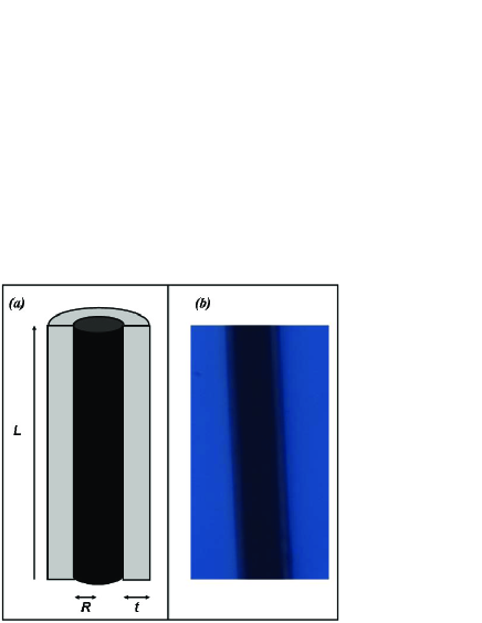
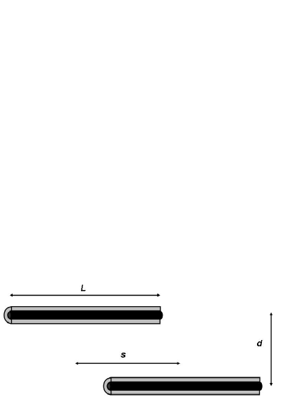
The purpose of this work is to develop an analytical model for the full long-range magnetostatic interaction between two microwires exploring the possibility of varying the magnetic coupling as a function of the wires position. The geometry of the wires is characterized by their external radii and length , as depicted in Fig. 1. The separation between the wires is written in terms of the interaxial distance, , and the horizontal separation, , as depicted in Fig. 2. Our model goes beyond the dipole-dipole approximation and lead us to obtain an analytical expression for the interaction in which the lengths and radii of the wires are taken into account. We focus on the interacting force in pairs of interacting wires, as a function of the distance between them, in order to gain insight on the understanding of the role of interactions on the plateaux that appears in the hysteresis loops.
II Experimental Methods
The experimental meaurements have been performed in glass coated amorphous bi-stable magnetic microwires with nominal composition Fe77.5Si7.5B15, with a saturation magnetization A/m, radii of m, and the thickness of the glass coating of m. They are fabricated by means of Taylor-Ulitovsky technique by which the molten metallic alloy and its glassy coating are rapidly quenched and drawn to a kind of composite microwire. Two samples with length of mm each were cut from a larger wire and fixed parallel by means of vacuum grease on a glass holder, with a separaton of m between the wires.
The morphology of microwires was investigated by a retro-optical microscope (Olimpus). The hysteresis curves were measured on a specially designed vibrating sample magnetometer (VSM), inserted within a pair of Helmholtz coils. These coils have sufficient field to saturate the wires and present the advantage of field homogeneity and the absence of remanent fields. We will focus our attention on measurements performed at room temperature because a low temperature there is a change in the domain structure of the microwires, probably owing to the increasing internal stresses induced by the different thermal expansion coefficients of the ferromagnetic alloy and the covering glass. SSC+00
III Theoretical calculations
We adopt a simplified approach in which the discrete distribution of magnetic moments of microwire is replaced by a continuous one characterized by a slowly varying magnetization . We consider wires for which so it is reasonable to assume an axial magnetization due to shape anisotropy, defined by , where is the unit vector parallel to the wire axis. The magnetostatic interaction between wires can be calculated from Aharoni96
where is the magnetization of the wire and is the magnetostatic potential of the microwire . The expression for this potential is given by
| (1) |
Note that the first term on the left-hand side of Eq. (1) vanishes, because the magnetization field is constant; furthermore, in the surface integral of Eq. (1) the only contributions arise from the upper and lower bases of the wire: the upper circle is located at and the lower on at . Due to the symmetry of the problem, we used the adecuate type of the cylindrical kernel for the integral Jackson62 , and after few manipulations, one finds that the integral expression for the scalar potential is given by
| (2) |
where is a Bessel function of first kind and order.
Now it is possible to calculate the magnetostatic interaction energy between two identical microwires using the magnetostatic field experienced by one of the wires due to the other. The final results reads
| (3) |
Equation (3) has been previously obtained for nanotubes. EAA+08 The general expression for the interaction energy between wires with axial magnetization, given by Eq. (3), can only be solved numerically. However, wires that motivated this work satisfy , in which case one can use that . With this approximation, Eq. (3) can be written in a very simple form as
| (4) |
Finally, the magnetostatic field can be written as a function of the magnetostatic interaction between the magnetic microwires and is given byEAA+09
| (5) |
IV Results
Figure 3 shows the hysteresis loop for two microwires of radii of m, length of mm, thickness of the glass coating of m, and interaxial separation m at room temperature. As observed, the magnetization process takes place in two steps: a jump near Oe, that must be ascribed to the reversion of a microwire; and an additional jump near Oe, corresponding to the reversion of the other microwire. The flat region before the second step corresponds to the magnetic field felt by one wire due to the other.

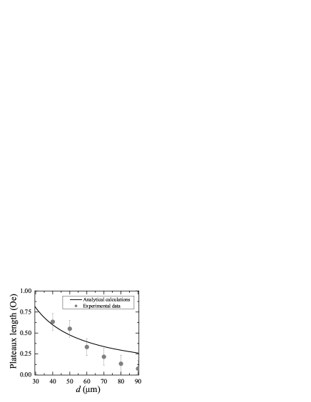
IV.1 Dependence of the interaxial separation of the wires on the magnetostatic field
Theoretical and experimental magnetostatic results are combined in Fig. 4. Experimental data for the magnetostatic field for different values of the interaxial separation are depicted by gray dots and the theoretical prediction is represented by the solid line. For the analytical calculations we have used an effective radii of m., which is smaller than the real radius, in order to compensate the approximation of consider a homogeneous magnetization in our model. PLK+07 It is clear that there is a strong dependence of the magnetostatic field on . Note the good agreement between experimental datapoints and analytical results for distances smaller than 80 m. The coupling rapidly decreases by increasing the separation between the wires, and become negligible for interaxial distances bigger than 80 m, at least within our experimental sensitivity. It can be understood if we consider that the stray field felt by one wire due to the other changes considerably if the wires are not completely parallel to each other. Thus, when the separation between the wires is big enough, small deviations may reduce the stray field produced by the wires.
IV.2 Dependence of the horizontal separation of the wires on the magnetostatic field
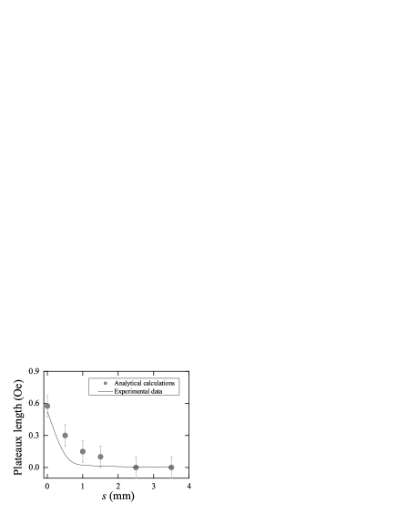
It is interesting to analyze the behavior of the magnetostatic plateaux as the interaxis distance, , is kept fixed and the horizontal separation, , is varied. Our results are combined in Fig. 5. Experimental data for the magnetostatic field of the system are depicted by gray dots and the solid line represents the analytical calculation. We observe a strong decrease of the magnetic field as the horizontal separation between wires is increased. Good agreement is obtained between the measured data and analytical calculations.
IV.3 Interacting force
A couple of isolated magnetic microwires can attract o repel each other upon approach depending on their relative orientations. For the microwires investigated the interacting force, , has been estimated to be of the other of (for m and ) to dynes (for m and ) for the case of interaxial separation in the range of parameters considered. For the horizontal separation, the interacting force is in the range between (for m and mm) to (for m and mm) dynes.
V Discussion and Conclusion
In summary, we have investigated the magnetostatic interaction between magnetic microwires. Using a continuous model we have obtained a simple expression to model the magnetostatic interaction in these particles. From our calculations and measurements we can conclude that the magnetostatic plateaux strongly depends on the geometry of the system. A couple of isolated magnetic microwires can attract o repel each other upon approach depending on their relative orientations. Based on microwires investigated the interacting force, , has been estimated to be of the other of (for m and mm) to dynes (for m and ) in the range of parameters considered. The perfomance of such experiment could provide the basis for testing the different theoretical models. Our results provide guidelines for the production of microstructures with tailored magnetic properties.
VI Acknowledgments
The authors are grateful to R. Bernal for micrograph images and to D. Altbir for useful discussions. This work was supported by Millennium Science Nucleus Basic and Applied Magnetism (project P06-022F), USAFOSR (award No FA9550-07-1-0040), and Fondecyt (Grants No. 11070010 and No. 1080164).
References
- (1) M. Vazquez, Advanced Magnetic Microwires, in: H. Kronmuller, S. Parkin (Eds.), Handbook of Magnetism and Advanced Magnetic Materials, Wiley, Chichester, UK, 2007, pp. 2193-2296.
- (2) H. Chiriac, M. Tibu, V. Dobrea, and I. Murgulescu, J. Optoelectron. Adv. Mater. 6, 647 (2004).
- (3) K. Mohri, and Y. Honkura, Sensor Lett. 5, 267 (2007).
- (4) E. Kaniusas, L. Mehnen, and H. Pfutzner, J. Magn. Magn. Mater. 254-255, 624 (2003).
- (5) J. Escrig, S. Allende, D. Altbir, M. Bahiana, J. Torrejon, G. Badini, and M. Vazquez, J. Appl. Phys. 105, 023907 (2009).
- (6) K. Yamada, S. Kasai, Y. Nakatani, K. Kobayashi, H. Kohno, A. Thiaville, and T. Ono, Nat. Mater. 6, 269 (2007).
- (7) I. Ogasawara, and S. Ueno, IEEE Trans. Magn. 31, 1219 (1995).
- (8) A. Zhukov, J. Gonzalez, M. Vazquez, V. Larin, and A. Tornucov, in: Nalwa HS, editor. Encyclopedia of Nanoscience and Nanotechnology, vol. X. Stevenson Ranch, CA: American Scientific Publishers; 2003. p.1.
- (9) R. Varga, K. Garcia, and M. Vazquez, Phys. Rev. Lett. 94, 017201 (2005).
- (10) L. C. Sampaio, E. H. C. P. Sinnecker, G. R. C. Cernicchiaro, M. Knobel, M. Vazquez, and J. Velazquez, Phys. Rev. B 61, 8976 (2000).
- (11) M. Knobel, L. C. Sampaio, E. H. C. P. Sinnecker, P. Vargas, and D. Altbir, J. Magn. Magn. Mater. 249, 60 (2002).
- (12) Q. -F. Zhan, J. -H. Gao, Y. -Q. Liang, N. -L. Di, and Z. -H. Cheng, Phys. Rev. B 72, 024428 (2005).
- (13) J. Velazquez, and M. Vazquez, J. Magn. Magn. Mater. 249, 89 (2002).
- (14) J. Velazquez, and M. Vazquez, Physica B 320, 230 (2002).
- (15) J. Velazquez, K. R. Pirota, and M. Vazquez, IEEE Trans. Magn. 39, 3049 (2003).
- (16) M. Beleggia, S. Tandon, Y. Zhu, and M. De Graef, J. Magn. Magn. Mater. 278, 270 (2004).
- (17) M. Beleggia, and M. De Graef, J. Magn. Magn. Mater. 285, L1 (2005).
- (18) D. Laroze, J. Escrig, P. Landeros, D. Altbir, M. Vazquez, and P. Vargas, Nanotechnology 18, 415708 (2007).
- (19) R. Piccin, D. Laroze, M. Knobel, P. Vargas, and M. Vazquez, EPL 78, 67004 (2007).
- (20) A. Aharoni, Introduction to the Theory of Ferromagnetism, Clarendon Press, Oxford (1996).
- (21) D. Jackson, Classical Electrodynamics, John Wiley & Son, Inc., (1962).
- (22) J. Escrig, S. Allende, D. Altbir, and M. Bahiana, Appl. Phys. Lett. 93, 023101 (2008).