Magnetoelastic nonlinear metamaterials
Abstract
We introduce the concept of magnetoelastic metamaterials with electromagnetic properties depending on elastic deformation. We predict a strong nonlinear and bistable response of such metamaterials caused by their structural reshaping in response to the applied electromagnetic field. In addition, we demonstrate experimentally the feasibility of the predicted effect.
The study of metamaterials became a prominent area of research, bringing together theoretical and applied electrodynamics, as well as electrical engineering and material science. Being initially intended to achieve negative refraction Smith et al. (2000); Pendry (2001), metamaterials quickly covered a much wider range of applications from microwaves to optics. Nonlinear metamaterials Zharov et al. (2003); Lapine et al. (2003) established a new research direction Agranovich et al. (2004); O’Brien et al. (2004); Scalora et al. (2005); Popov and Shalaev (2006); Padilla et al. (2006); Gabitov et al. (2006); Syms et al. (2008); Poutrina et al. (2010) giving rise to fruitful ideas for tunable and active artificial materials Boardman et al. (2011).
The initial way to provide strong nonlinearity to metamaterials was found in either employing a nonlinear host medium Zharov et al. (2003) or by engineering the elements of a metamaterial with a nonlinear component Lapine et al. (2003). In those approaches the nonlinear response is obtained on the level of individual elements. On the other hand, by varying the mutual interaction between elements one can efficiently control bulk metamaterial properties Lapine et al. (2009); Powell et al. (2010). It is therefore quite promising to explore the possibilities of nonlinear mutual interaction in metamaterials.
In this Letter, we propose a novel concept of magnetoelastic metamaterials, where nonlinearity arises from a collective response. This is achieved by providing a mechanical degree of freedom so that the electromagnetic interaction in the metamaterial lattice is supplemented by elastic interaction. This enables the electromagnetically induced forces to change the metamaterial shape, thus changing its effective properties. Consequently, such a metamaterial exhibits efficient self-action, which leads to strong nonlinear effects and non-trivial bistability.
To illustrate this concept, we consider a magnetic metamaterial composed of a lattice of resonant elements, such as split-ring resonators (SRRs) or capacitively-loaded rings (CLRs). We select an anisotropic arrangement (Fig. 1) with all the resonators having the same orientation, so that the inter-layer distance can be made sufficiently small to ensure a stronger interaction. For simplicity, we choose a circular shape of resonators, however this does not limit the generality of the predicted phenomena. For the convenience of analytical expressions, we use the dimensionless lattice parameters and , normalized to the resonator radius .

In response to electromagnetic waves with magnetic field along the axial direction, such a metamaterial shows resonant magnetic behavior Gorkunov et al. (2002). The currents induced in the resonators not only affect each other through mutual inductance, but also result in an attractive force between the resonators (it is attractive provided that the neighboring currents are in phase). So if the resonators are allowed to move along the axial direction, they will displace from their original positions, thus changing their mutual impedance, which in turn affects the current amplitudes, interaction forces, and so on. The balance is kept with a restoring force, which originates from the elastic properties of the host medium.
We consider a quasi-stationary regime, where the characteristic response times for mechanical movements are much larger than the period of electromagnetic oscillations. We also assume that the electromagnetic resonance frequency is such that the wavelength is much larger than element size and lattice constants (this can be easily achieved e.g. by using CLRs with an appropriate capacitance, or broadside-coupled SRRs Marqués et al. (2008) with sufficiently small gaps). In this case, the currents induced in neighboring elements are all in phase and also uniform along the resonator circumference, so that the attraction force can be evaluated in the same way as the static force for DC currents, weighted with a time-averaged current amplitude, . At the same time, electric interaction is irrelevant in a quasi-static situation, or otherwise can be minimized by choosing an appropriate mutual orientation of the rings Powell et al. (2010).
For identical rings sharing a common axis and carrying currents with amplitude , the force acting between them has only the axial component, calculated as Landau and Lifschitz (1984)
| (1) |
where , are the complete elliptic integrals of first and second kind with the parameter .
In the limit of remote rings (), the expression (1) can be expanded with respect to as a small parameter, with elliptic integrals evaluated explicitly. This yields a long distance limit
| (2) |
Naturally, this result agrees, up to different terms, with the dipole approximation valid for large distances. This allows us to take into account far-neighbor interactions consistently: the summation over remote rings quickly converges thanks to the fourth power decay, so within a relevant volume we can still assume that the currents are not affected by retardation.
We assume that the lateral lattice constant is reasonably large so that additional forces between the rings in the neighboring columns can be neglected. Then the total compression force acting between any two rings in the bulk, can be shown to have the following form:
| (3) |
where is number of rings for which the approximate solution (2) is not yet sufficiently precise, while for the remaining rings the quickly converging summation over (2) yields a minor addition which can be neglected in practice. The value of depends on the lattice density, being for example of the order of 100 for and of 20 for . For practical purposes, it is convenient to introduce a specific multiplication factor to obtain directly from (1). Empirically, it turns out that is closely proportional to so the exact summation (3) can be replaced with quick approximate calculation
| (4) |
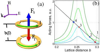
We now assume that the elastic force which balances the magnetic attraction, obeys a Hooke’s law, , with a generic stiffness coefficient , and the initial lattice constant . Thus the distance where equilibrium is achieved will be determined by a balance between the total compression force in the bulk , and the elastic force [Fig. 2(a)]:
| (5) |
We must impose an artificial limit on how small can be, to reflect the unavoidable technological restrictions as well as to ensure a reasonable limit on the linear elasticity law, which simplifies the analysis.
Self-action, resulting in nonlinear behavior, occurs through the mutual inductance between the rings, which also depends on . In metamaterials, the effect of mutual interaction between all the rings, is accounted for by the so-called lattice sum , which depends on the lattice type and parameters. It can be numerically calculated as explained in Ref. Gorkunov et al. (2002). The complete impedance equation
| (6) |
together with the equilibrium equation (5), forms a system of coupled equations, which can be numerically solved to yield and for a given incident amplitude and frequency . Then the magnetization of the metamaterial is obtained as , where the effect is further enhanced through the dependence of the volumetric density of rings, , on . Thus, we can characterize our metamaterial with a nonlinear and resonant dependence.
To outline the expected phenomena, we depict some examples of the interplay of the involved forces in Fig. 2. The solutions to the balance (5) are graphically seen as the crossing points, and the stable equilibrium positions are such that for an attempted decrease in . Note that the resonant nature of the currents, induced in the rings depending on [see Eq. (6)], defines the resonant character of the force . Thus, when three mathematical solutions are available, only two are actually stable; or otherwise there is a single stable state. The phenomenology is qualitatively clear: when the current amplitude exceeds certain threshold [where indicated with cross “2” in Fig. 2(b)], the initial “right-side” equilibrium (such as at circle “1”) cannot be achieved, so the lattice distance attempts to collapse. However this also changes the mutual interaction dramatically, leading to a significant shift of the resonance frequency, so the current magnitude drops, permitting the other (“left-side”) equilibrium state (Fig. 2, circle “4”), corresponding to the same force curve. On the other hand, with a decreasing amplitude, the “left-side” balance remains stable as long as the peak attraction force is sufficient to counter the elastic force (down to an unstable point, cross “3”), from where the system jumps back to the corresponding “right-side” solution (circle “1”).
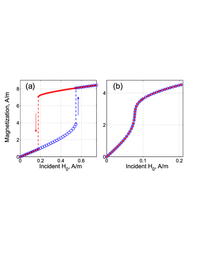
We illustrate typical patterns of the arising nonlinearity (Fig. 3) with elements of radius mm, resonating individually at 1 GHz (the frequency values below are normalized with respect to the corresponding angular frequency ), with a quality factor of 100. These are arranged in a metamaterial with , , , with a stiffness coefficient mN/m. As we show below, although the required coefficient is rather small with respect to bulk conventional materials, it can be realized in practice with the help of appropriately bend thin filaments or small plastic springs with realistic geometrical parameters, which fit to the suggested geometry.
At frequencies lower than the eigenfrequency of the initial state, we observe a slightly nonlinear dependence as the amplitude grows, until the metamaterial abruptly switches to a stronger compression. However, when the amplitude is decreased, the metamaterial remains in the compressed state until much lower magnitudes, exhibiting a hysteresis-like behavior [Fig. 3(a)]. But close to the original resonance, the hysteresis disappears while the nonlinearity is quite strong [Fig. 3(b)].
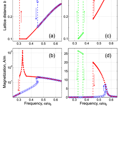
More spectacular phenomena can be observed with the frequency dependence, which reveals the entire drama of complex bistable behavior (Fig. 4). With moderate to high amplitudes, lattice distance declines slowly with growing frequency, until at some stage the initial balance of forces is lost and metamaterial jumps to a more compressed state, from where it gradually returns back to the original state with further frequency increase; the magnetization pattern reflects these changes [see the blue circles in Figs. 4 (a, b)]. But when the frequency is decreased from the high values, the structure remains in the compressed state across that threshold, and continues to compress until the mechanical limit at is reached, where it remains until the currents induced at still decreasing frequency become low enough to release the entire jump back to the ground state [Fig. 4(a), red bullets]. This is followed by the magnetization, but note that in the frequency range of full compression the response of the metamaterial is linear and hence we can observe a purely linear resonance [see the red bullets in Fig. 4(b)].
However, at low amplitudes, we can observe highly unusual behavior [Figs. 4 (c, d)]. The frequency hysteresis described above still applies, but in addition there appears a frequency range where the metamaterial is stable in a compressed state, but which, however, cannot be directly accessed in this hysteresis loop [see the green squares in Figs. 4 (c, d)]. The only ways to reach this range of compressions are to push the structure once with an external mechanical force, or to temporarily increase the intensity. Once there, the metamaterial remains stable in the corresponding frequency window, jumping to the ground state when decreasing or increasing the frequency past the window limits. This spectacular effect exists because below certain amplitudes, the currents induced in the intermediate range of are not sufficient to hold the force balance even at resonance; however they are still able to do it for smaller because of the effectively law in Eq. (4). The range of amplitudes where this can be observed, is relatively narrow (in our example, between 0.38 and 0.41 A/m), with the corresponding frequency range becoming increasingly narrow with decreasing , until finally disappearing while the main hysteresis is still in place up to very low amplitudes.
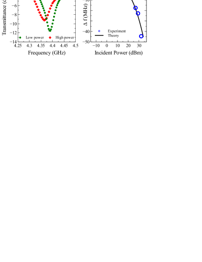
In order to demonstrate the plausibility of the predicted effect, we perform a pump-probe experiment for a pair of closely spaced SRRs, having 4.6 mm radius, 1 mm gap and made of 0.18 mm-thick copper wire. We suspend the SRRs parallel to the axis of a WR 229 rectangular waveguide, at a distance of 1.4 mm (), on a dielectric rod with two groves, so that the rings are able to swing towards each other when an attractive force is induced. To provide for an elastic force, we use four U-shaped keratin filaments between the resonators. The waveguide is excited by combined signal of the vector network analyzer (Rhode and Schwartz ZVB-20) and a continuous wave pump generated by a signal generator (HP 8673B), which is amplified by a signal amplifier (HP 83020A). Frequency scans are performed using a vector network analyser with a signal power of dBm, while the continuous wave pump is applied at 4.38 GHz. The spectrum of the incident signal is measured using a broadband directional coupler.
Figure 5 demonstrates a remarkable effect of increasing electromagnetic wave power, with a resonance frequency shift of 44.5 MHz. The experimental power dependence of the resonance matches very well with the theory developed above (upon the straightforward amendments required to account for two resonators instead of a bulk material), with the corresponding parameters and assuming a stiffness coefficient of about 1.3 mN/m. Note the latter is very close to the one used for theoretical results and therefore proves them absolutely feasible.
In summary, we have proposed a novel type of metamaterial introducing mechanical degrees of freedom, and demonstrated that this provides a clearly measurable effect with the parameters very close to our assumptions. The magnetoelastic coupling mechanism leads to many interesting nonlinear effects which can be useful for further theoretical development as well as for future applications in microwave, THz and optical range.
This work was supported by the Australian Research Council. The authors thank M. Gorkunov and A. Sukhorukov for useful discussions.
References
- Smith et al. (2000) D. R. Smith, W. J. Padilla, D. C. Vier, S. C. Nemat-Nasser, and S. Schultz, Phys. Rev. Lett. 84, 4184 (2000).
- Pendry (2001) J. B. Pendry, Physics World 14, 47 (2001).
- Zharov et al. (2003) A. A. Zharov, I. V. Shadrivov, and Yu. S. Kivshar, Phys. Rev. Lett. 91, 037401 (2003).
- Lapine et al. (2003) M. Lapine, M. Gorkunov, and K. H. Ringhofer, Phys. Rev. E 67, 065601 (2003).
- Agranovich et al. (2004) V. M. Agranovich, Y. R. Shen, R. H. Baughman, and A. A. Zakhidov, Phys. Rev. B 69, 165112 (2004).
- O’Brien et al. (2004) S. O’Brien, D. McPeake, S. A. Ramakrishna, and J. B. Pendry, Phys. Rev. B 69, 241101(R) (2004).
- Scalora et al. (2005) M. Scalora, M. S. Syrchin, N. Akozbek, E. Y. Poliakov, G. D’Aguanno, N. Mattiucci, M. J. Bloemer, and A. M. Zheltikov, Phys. Rev. Lett. 95, 013902 (2005).
- Popov and Shalaev (2006) A. K. Popov and V. M. Shalaev, Opt. Lett. 31, 2169 (2006).
- Padilla et al. (2006) W. J. Padilla, A. J. Taylor, C. Highstrete, M. Lee, and R. D. Averitt, Phys. Rev. Lett. 96, 107401 (2006).
- Gabitov et al. (2006) I. R. Gabitov, R. A. Indik, N. M. Litchinitser, A. I. Maimistov, V. M. Shalaev, and J. E. Soneson, J. Opt. Soc. Am. B 23, 535 (2006).
- Syms et al. (2008) R. R. A. Syms, L. Solymar, and I. R. Young, Metamaterials 2, 122 (2008).
- Poutrina et al. (2010) E. Poutrina, D. Huang, and D. R. Smith, New J. Phys. 12, 093010 (2010).
- Boardman et al. (2011) A. Boardman, V. Grimalsky, Yu. Kivshar, S. Koshevaya, M. Lapine, N. Litchinitser, V. Malnev, M. Noginov, Y. Rapoport, and V. M. Shalaev, Laser Photonics Rev. 5, 287 (2011).
- Lapine et al. (2009) M. Lapine, M. Gorkunov, D. A. Powell, I. V. Shadrivov, R. Marqués, and Yu. S. Kivshar, Appl. Phys. Lett. 95, 084105 (2009).
- Powell et al. (2010) D. A. Powell, M. Lapine, M. Gorkunov, I. V. Shadrivov, and Yu. S. Kivshar, Phys. Rev. B 82, 155128 (2010).
- Gorkunov et al. (2002) M. Gorkunov, M. Lapine, E. Shamonina, and K. H. Ringhofer, Eur. Phys. J. B 28, 263 (2002).
- Marqués et al. (2008) R. Marqués, F. Martín, and M. Sorolla, Metamaterials with Negative Parameters (Wiley, 2008).
- Landau and Lifschitz (1984) L. D. Landau and E. M. Lifschitz, Electrodynamics of Continuous Media (Pergamon Press, Oxford, 1984).