Filling and wetting transitions of nematic liquid crystals on sinusoidal substrates
Abstract
Close to sinusoidal substrates, simple fluids may undergo a filling transition, in which the fluid passes from a dry to a filled state, where the interface remains unbent but bound to the substrate. Increasing the surface field, the interface unbinds and a wetting transition occurs. We show that this double-transition sequence may be strongly modified in the case of ordered fluids, such as nematic liquid crystals. Depending on the preferred orientation of the nematic molecules at the structured substrate and at the isotropic-nematic interface, the filling transition may not exist, and the fluid passes directly from a dry to a complete-wet state, with the interface far from the substrate. More interestingly, in other situations, the complete wetting transition may be prevented, and the fluid passes from a dry to a filled state, and remains in this configuration, with the interface always attached to the substrate, even for very large surface fields. Both transitions are only observed for a same substrate in a narrow range of amplitudes.
pacs:
61.30.-v,61.30.Dk,61.30.Hn,61.30.JfI Introduction
Wetting on smoothly structured substrates show a rich phenomenology. For simple fluids, the wetting behavior on structured substrates presents a variety of phenomena Rascon_2000_2 ; Callies_Quere_2005 ; Bonn_etal_2009 , for which several physical laws were theoretically proposed, as the Wenzel Wenzel_1936 or the Cassie-Baxter laws Cassie_Baxter_1944 . These laws extend Young’s law deGennes_1985 for planar substrates, including new substrate geometrical parameters. If these laws are justified in some situations Patricio_Pham_RomeroEnrique_2008 , they may also fail in general theoretical or experimental conditions Swain_1998 . In addition to the usual wetting transition, simple fluids at bulk coexistence may present other surface transitions as the filling transition Rascon_1999 ; Rejmer_2000 . From a thermodynamical point of view, the filling transition in simple fluids always precedes a complete wetting transition. However, the filling transition may not exist for shallow substrates Rascon_1999 , but if it does exist, it always precedes the wetting transition.
The existence of long-range order in complex fluids may alter the scenario depicted above Patricio_Romero_etal_2011 . In a nematic liquid crystal, there is an orientational (continuous) long-range order. However, the presence of substrates which favor specific orientations frustrate the liquid crystal tendency to align along a given direction. As a consequence, elastic distortions emerge, altering the subtle balance between the different free-energy contributions which lead to the surface transitions on structured substrates.
In this paper, we show that the filling-wetting sequence which is observed in simple fluids on sinusoidal substrates may be deeply modified when we have a nematic liquid crystal instead of a simple fluid. Depending on the physical elastic parameters of the nematic, several scenarios may occur: we may only have a wetting transition; or a filling transition only, preventing the subsequent complete wetting transition; or the double sequence as in the simple fluid case. Both filling and wetting transitions are only observed for the same geometry in a narrow range of amplitudes.
This article is organized as follows: in Section II.A. we briefly review the main simple analytical results about filling and wetting transitions of simple fluids. In Section II.B., we extend these results to nematic liquid crystal systems. In Section III, we use the Landau-de Gennes model of nematics to study their wetting behavior on a sinusoidal substrate. At the end, we draw some conclusions.
II Macroscopic analysis
II.1 Thermodynamic description of filling and wetting transitions for simple fluids
In this section, we review the simple description of filling and wetting transitions for simple fluids, following the ideas presented in Rejmer_2000 . To that end, let us consider a structured substrate, like the one presented in Fig. 1. The substrate is translationally invariant along , with being the total length along this direction, and periodic along the -axis with a period . The substrate profile can be described by a simple even function . To simplify the analysis, we consider a monotonically increasing function for .

We suppose the substrate favors the liquid phase and consider three possible interfacial states: i) dry, ii) filled and iii) wet (see Fig. 1). If the bulk free energies of the vapor and liquid phases are the same (so they can be set equal to zero), and if we neglect interactions between the interfaces, then the energies associated with each state will be simply the sum of surface energy terms. Let us denote as the whole substrate area, its projection on the plane and the excess interfacial free energy. Then, the free energy of the dry state (see Fig. 1(i)) is
| (1) |
where is the vapor-wall (substrate) surface tension.
The free energy corresponding to the filled interfacial state (see Fig. 1(ii)) is
| (2) |
where is the liquid-wall (substrate) surface tension, is the liquid-vapor surface tension, and is the substrate area in contact with the liquid phase, which can be obtained in terms of the abscissa of the contact line of the filled region with the substrate as:
| (3) |
where is the derivative of with respect to . The value of can be obtained by minimisation of the free energy Eq. (2) with respect to it. Making use of Young’s law, which relates the surface tensions mentioned above with the contact angle of a sessile drop of the liquid in a planar substrate, ,
| (4) |
it can be shown that the minimum energy condition is fulfilled when satisfies Rejmer_2000 :
| (5) | |||||
showing that the filling region must make contact with the substrate with an angle . For smooth substrates, this solution is a local minimum only if .
Finally, the free energy for the wet state (see Fig. 1(iii)) is given by:
| (6) |
Different transitions between the different interfacial states can be observed. The transition from the dry state directly to the wet state is possible when the energies of these configurations are the same, that is,
| (7) |
Using Young’s law Eq. (4), it is possible to deduce from Eq. (7) Wenzel’s law for the dry-to-wet transition:
| (8) |
where is the roughness of the substrate. As , a wetting transition may occur. However, this transition may be preempted by the presence of filled states. The filling or unbending transition between a dry and a filled state may occur if the free energies of these interfacial states are the same:
| (9) |
which leads to the equation
| (10) |
where . If this transition occurs at a lower temperature than the wetting transition predicted by the Wenzel law (i.e. for larger values of , as usually decreases with temperature), then a filling transition occurs and Wenzel’s law does not hold. Under these conditions, macroscopics dictates that the wetting transition between a filled and a wet interfacial state must occur under the same conditions as in the planar substrate (i.e. ). However, this prediction can be changed as interactions between the substrate and the liquid-vapor interface are taken into account. So, if there is a first-order wetting transition for the planar substrate, the wetting transition is still first-order but shifted to larger values of (smaller temperatures)Rejmer_2000 . On the other hand, for planar continuous wetting its location and nature is unchanged Rascon_1999 .
II.2 Thermodynamic description of filling and wetting transitions for nematic fluids

If instead of a simple fluid under saturation conditions, we have a liquid crystal at the nematic-isotropic phase coexistence, some new phenomena will inevitably arise. Let us consider that the substrate favors the nematic phase at a particular anchoring condition. From a thermodynamical point of view, if the bulk free energies of the phases are the same, the total energy of the nematic interfacial state has a new positive extra term , corresponding to the Frank elastic energy of the nematic distortions imposed by the anchoring at the substrate. Fig.2 shows schematically an example of a nematic phase in contact with a substrate with homeotropic anchoring conditions (however, the theoretical arguments presented here are very general, and independent on the particular anchoring conditions involved). The total free energy of this interfacial state can be written as
| (11) |
The elastic deformation creates an effective long-range repulsion between the substrate and the interface: the closer the interface is to the substrate, the more constrained the order will be, leading to higher energies. As the interface goes to infinity, the system will only have a characteristic length scale, that is imposed by the substrate (see Fig. 2). If no defect arises, the elastic contribution may be simply estimated as , where is the Frank elastic constant, and is a reduced elastic contribution to the interfacial free energy, only dependent on the substrate geometry, but not on its scale Berreman_1972 . In some cases, topological defects nucleate close to or on the substrate. The presence of defects imposed by the substrate introduce a dependence on the reduced elastic contribution RomeroEnrique_Pham_Patricio_2010 . This dependence is easily justified. If the defects are induced by the substrate, they will place themselves at a distance of order of (the characteristic length of the substrate), usually close to its crests and/or troughs. On the other hand, the cut-off length is given by the size of the defects, which scales with the correlation length .
The dry-to-nematic wet transition may be derived from the generalized Wenzel law Patricio_Pham_RomeroEnrique_2008 :
that can be rewritten as
| (12) |
For large enough substrate lengths, , the effects of elastic terms are unimportant, and Wenzel’s law is recovered. Usually, and are not independent, and their ratio scales with the correlation length . In fact, using Landau-de Gennes model for nematic liquid crystals (see next section), it is possible to show that (at coexistence temperature).
For the simple fluid case (), the dry-to-wet transition for the rough substrate occurs always before the wetting transition for the planar substrate, as the surface field or the temperature is increased. In contrast, for the nematic case, the wetting transition for a rough substrate may occur either before (if the roughness is more important) or after the wetting transition for the planar substrate (if the elastic deformations are more important). These deviations with respect to Wenzel’s law are enhanced if defects are present, as the elastic term of the generalized Wenzel’s law (Eq. (12)) will decay slower with increasing . The sawtoothed substrate exemplifies this effect RomeroEnrique_Pham_Patricio_2010 .
We now turn to the case of nematic filled states. Once again, it is useful to first consider configurations without defects, which do not appear if the substrate is shallow enough. Given the fact that the nematic-isotropic interface favors a particular nematic anchoring deGennes_1970 , if the interface is near the substrate, it will induce strong elastic deformations, because the nematic director is constrained to follow the anchoring conditions on both the interface and the substrate. Thus the elastic energy of the deformations may be large enough to prevent any filling transition, even if it would normally occur in the case of a simple fluid. It should also be pointed out that the interfacial free energies of the filled and wet states are normally very close to each other Rejmer_2000 , and a very tiny perturbation can exchange their relative stability.
If the substrate imposes defects on the nematic matrix, a different picture emerges. The case of a sinusoidal grating is studied in detail in the next section. If the substrate is rough enough, and if the nematic-isotropic interface favors for example homogeneous planar anchoring, then the filled state (with the interface placed in between the crests of the sinusoidal substrate), may always have a smaller energy than the wet state for in the latter case, a periodic array of defects is necessarily created at the top of each crest.
III The sinusoidal substrate. Numerical results
In this section, in order to substantiate our arguments, let us consider a nematic liquid crystal in contact with a sinusoidal grating, characterized by a wavevector , and an amplitude (see also Fig. 1):
| (13) |
At the substrate, the nematic molecules preferentially align homeotropically, i.e. perpendicularly to the substrate. The system is translationally invariant along the out-of-plane axis and periodic along the axis. Finally we impose that, far from the substrate, we have an isotropic ordering.
III.1 The Landau-de Gennes model
In the Landau-de Gennes (LdG) model, both isotropic and nematic phases can be locally represented by a traceless, symmetric order-parameter tensor with components:
| (14) |
where are the Cartesian components of the director field , is the nematic order parameter which measures the orientational ordering along the nematic director, and is the biaxiality parameter, which measures the ordering of the molecules on the orientations perpendicular to , characterized by the eigenvectors and . In our model, we will only consider in-plane de- formations, although out-of-plane or twist deformations may also be important (a twist instability may occur for particular choices of parameters Patricio_Telo_Dietrich_2002 ). In this case, , and the tensor order parameter has only three independent components (namely , , and ).
The LdG free energy may be written as
| (15) |
where is the bulk free energy density, is the elastic free energy density, and is the surface free energy, defined as deGennes_Prost_1995 :
| (16) | |||
| (17) | |||
| (18) |
where depends linearly on the temperature, and are positive constants, and and are positive parameters related to the elastic constants. If we rescale all the variables as follows Andrienko_Tasinkevytch_Patricio_etal_2004 : , the positions , where the correlation length is defined as , and , we get , with rescaled free energy densities:
| (19) | |||
| (20) | |||
| (21) |
Here is a dimensionless temperature, is an elastic dimensionless parameter (for stability reasons, the elastic parameter is restricted to the values, ) and is the dimensionless anchoring strength. Hereafter, we will consider these rescaled expressions, so we will drop the tilde notation.
In our model, we will place ourselves at coexistence temperature, , for which the bulk free-energy density has two minima, corresponding to for rescaled scalar order parameters (isotropic phase) and (nematic phase). It is important to note that the order parameter in the coexisting nematic phase is rescaled, so its value in real units is , which must be smaller than 1 (typically ). If the elastic parameter is positive (negative), the nematic prefers to align parallel (perpendicular) to a possible nematic-isotropic interface. Finally, defines the favored tensor at the substrate. We favor a homeotropic alignment of the nematic by setting , with the normal vector to the substrate, establishing a direct connection to previous papers Sheng_1976 ; Sheng_1982 ; Braun_1996 .
III.2 Numerical procedure
For every set of model parameters, we numerically minimized the Landau-de Gennes free energy, using a conjugate-gradient method. The numerical discretization of the continuum problem was performed with a finite-element method combined with adaptive meshing in order to resolve the different length scales Patricio_Tasinkevych_Telo_2002 . Due to the translational symmetry along the axis and the periodicity on the axis, we restricted the minimisation to a section of the system perpendicular to the axis and with a width along the axis equal to the period of the substrate. We used periodic boundary conditions on the lateral sides, and the fluid on the substrate, which corresponds to the bottom boundary of our unit cell, has not an imposed ordering or anchoring, although a nematic phase with homeotropic orientation is energetically favourable. Finally, we impose different fixed boundary conditions at the cell top (which we place at a large height ) in order to explore the different interfacial states we may observe. The value of was varied until we found convergence in the free energy. In order to find the dry () or the filling () interfacial states, we fix a bulk isotropic phase on top of the cell. Under these conditions, different states may be obtained when we vary the initial condition (for example, by considering initial conditions with different heights for the nematic filling region). The complete wet () interfacial states are obtained by imposing a fixed nematic phase at the cell top with a homogeneous nematic director along either the axis () or the axis () (see Fig. 4 for illustrations). The free energy for the wet states is calculated by adding to the numerically obtained free energy the contribution of an isotropic-nematic interface parallel to the plane, , calculated also numerically (and in some cases analytically) and corresponding to the most favoured anchoring conditions (homeotropic to the interface for , planar for ). In this way we consider the presence of a nematic-isotropic interface infinitely away from the substrate in the wet state, allowing us to neglect the elastic deformations which may exist between the top cell and the nematic-isotropic interface. The true equilibrium state will be the state which gives the least free energy at the same thermodynamic conditions.
III.3 Numerical results
III.3.1 Case of
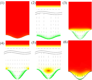
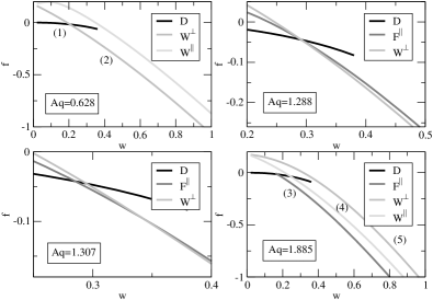
As an example, in Fig. 3 we plot the free energy per projected unit area corresponding to the most relevant interfacial states for , (favoring a parallel anchoring at the nematic-isotropic interface) and different values of , , and . For the shallowest case we plot the branches corresponding to states (which is the most stable for small ), states and . No states are observed. As it is expected, the branch has always larger free energy than the others, since for shallow substrates the elastic deformations are stronger for this state than for the state. On the other hand, the and branches intersect at a first-order wetting transition for , so branch is the most stable for (typical configurations for both and states are shown at Fig.4-(1) and 4-(2)).
For rougher substrates, the scenario is completely different (see Fig. 3). For four different (locally) stable branches are observed: states (again the most stable for small ), states, states and a filled state where the nematic is planar at the nematic-isotropic interface. This new state will be denoted by (a typical configuration is shown in Fig. 4-(3)). For small , the nematic-isotropic interface is almost parallel to the plane. As increases, the position of the nematic-isotropic interface for the state is lifted and curved slightly, and it eventually pins at the crests of the substrate. Regarding the complete wet states, the free energy of the branch is always larger than those of the states (unlike for shallow wedges). Typical configurations are shown in Fig. 4-(4) () and 4-(5) (). Now roughness induces larger deformations in , leading to a higher free energy. In both cases topological defects may nucleate either close to the substrate troughs ( states) or the crests ( states). We can see that the branch has always a smaller energy than the wetting states, so there is a first-order filling transition between a and state at . However, we do not observe a wetting transition, even for large . This latter feature can be rationalised by the fact that the state does not present topological defects as does the state.
The crossover from the scenarios described above occurs at intermediate values of . Above some value of the branch of emerges as a metastable branch. At a triple point occurs, since the , and branches intersect at the same value of (see Fig. 3). Above this triple point, the states branch crosses both the and branches, so filling and wetting transitions are observed for the same geometry. However, the value of for the wetting transition has a steep increase with , so the wetting transition is no longer observable for larger than .
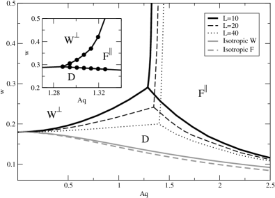
The global adsorption phase diagram for is shown in Fig. 5. The domains for the different possible stable phases (, or ) are divided by first-order transition lines which meet at a triple point. Note that the - transition line is almost vertical, so the range in which both filling and wetting transitions are observed is quite narrow. As the substrate wavelength increases, the importance of the elastic term of the nematic free energy diminishes, and the - and - transition lines shift towards lower values of , approaching the values obtained for simple fluids within the macroscopic theory outlined in Section II. However, due to the presence of elastic distortions, larger deviations than for simple fluids can be observed in all the cases,
For the - wetting transition we can estimate this deviation through the modified Wenzel law prediction, Eq. (12). The different terms in this expression can either be evaluated exactly or estimated numerically. Firstly, the nematic order parameter for the LdG model close to a planar substrate in the presence of a bulk nematic or isotropic phase can be solved analytically RomeroEnrique_Pham_Patricio_2010 . The exact solutions of the corresponding Euler-Lagrange equations for the order parameter profiles, , are given by
| (22) |
where and are, respectively, the nematic order parameter profiles, as a function of the distance to the planar substrate , corresponding to a bulk nematic or isotropic phase in bulk, and are their values in contact with the substrate. The surface tensions between the planar substrate and the nematic or isotropic phase are given by
| (23) | |||||
| (24) | |||||
The nematic order parameter values at contact with the substrate can be obtained from the boundary condition as:
| (25) |
The planar contact angle is obtained from Young’s law
| (26) |
where for .
The roughness of a sinusoidal substrate, is given in terms of the amplitude and the wavenumber as:
| (27) |
where is the complete elliptic integral of second kind.
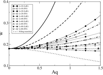
Finally, for the elastic term we have to resort to some numerical calculations. As a first estimate, we may use Berreman’s approximation Berreman_1972 . Fig. 6 shows the comparison between the numerical and the modified Wenzel law predictions for the - transition line when Berreman’s approach for the elastic free-energy contribution is used. They are in qualitative agreement: for small the wetting transition is shifted towards larger values of , and as increases, the transition line moves down, approaching Wenzel’s prediction, Eq. (8). A similar behaviour was observed for the wetting transition of the saw-toothed substrate Patricio_Pham_RomeroEnrique_2008 ; Patricio_Romero_etal_2011 . However, there are quantitative discrepancies even for the largest system considered. The explanation for these discrepancies is that Berreman’s expression is only accurate for small and very large (strong anchoring conditions), but it overestimates the exact result of Frank theory Barbero_etal_2008 . So, we have estimated the elastic energy obtained by using a Frank-Oseen (FO) model with a Rapini-Papoular surface contribution, where the interaction strength (which depends on ) is obtained from a contrained minimisation of the LdG model in presence of a planar wall and a given nematic director orientation at a distance RomeroEnrique_Pham_Patricio_2010 . We used a similar adaptative-mesh finite-element method to minimise the FO model to that explained above for the LdG model. Our results show that, for and assuming strong anchoring conditions, the elastic contribution is reduced, taking a value of around of that obtained from Berreman’s expression. However, if weak anchoring is considered, a further reduction is observed, even for . This fact contrasts with our previous results in the sawtoothed substrate, in which the strong anchoring regime is reached for relatively smaller values of . When the numerically obtained values of are used in Eq. (12), the predictions for the wetting transition from the generalized Wenzel law are in very good agreement with the full numerical values from the LdG model for (see Fig. 6).
III.3.2 Case of or
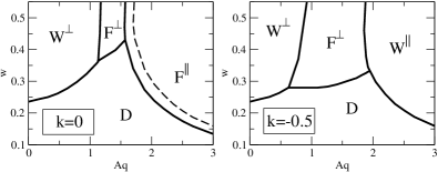
Now we turn to the effect of in the adsorption phase diagram. As it was already stated, for the nematic fluid has a preferred planar anchoring at the interface. As decreases the free-energy cost to anchor the nematic in a parallel or perpendicular orientation approach each other and become identical for . If we further decrease , the system starts to prefer a perpendicular orientation at the interface. As a consequence, new interfacial states emerge, as the filled state (see Fig. 4-(6)). These new states appear at intermediate values of for large , and the interface shows a pronounced curvature following the substrate shape. The global adsorption phase diagrams for are shown in Fig. 7. Again, the continuous lines correspond to first-order transition lines which meet at triple points. For , the region of the phase diagram corresponding to states is located between the regions corresponding to and states, with almost vertical boundaries between them. The - transition is weaker than the other transitions, so it is almost observed as a crossover for . Finally, the states free-energy branch approach to the free-energy branch. The dashed line corresponds to the (metastable) - transition. For , the states become the stable states for large and . So, the phase diagram is reminiscent of that for , by swapping the states with the states. It is interesting to note that it is possible to observe reentrance of states as is increased: the fluid undergoes a wetting transition from the state to the state, and for larger values of there is a reverse dewetting transition from the to the state. However, this sequence of three transitions is limited to a very narrow range of values of .
IV Conclusions
In this article we have shown that the filling and wetting transition sequence of an isotropic fluid on a sinusoidal substrate is deeply changed for nematic liquid crystals. Substrates favoring perpendicular anchoring in contact with nematic liquid crystals, that favor parallel anchoring at the nematic-isotropic interface, exhibit only a wetting (and not filling) transition for small , while for large only filling (and not wetting) transitions occur. In the latter case, the complete wetting transition is prevented by the pinning of the nematic-isotropic interface at the crests of the sinusoidal substrate, thus hindering the nucleation of topological defects that would otherwise be present in the wet configuration at large enough anchoring strengths. When perpendicular anchoring is favored at both the substrate and the interface, the filling and wetting transition lines change places. In this case the wetting transition may occur for larger , whilst the filling transition occurs for intermediate . Finally, in conditions such that the anchoring at the nematic-isotropic interface may be either planar or homeotropic, the phase diagram shows mixed features of the two previous cases. The analysis of these situations is far more complex than in the previous cases, as any perturbation can change the delicate balance between the different contributions to the free energy.
In order to check the validity of the phenomenological generalized Wenzel’s law, Eq. (12), we have compared its predictions with the numerical transition values for the one-step wetting transition. We see that they are in excellent agreement for . This fact shows that elastic effects are important in the range of values of wavelength considered in our work. In particular, they stabilize the state with respect to the state, as elastic deformations are a positive contribution to the surface free energy only present in the latter state. On the other hand, the location of the wetting transition approaches the value predicted by the typical Wenzel’s law, Eq. (8), when increases.
Acknowledgements.
We acknowledge the support from FCT (Portugal) through Grant No. PTDC/FIS/098254/2008, SFRH/BPD/40327/2007 (N. M. S.), Pluriannual Contract with CFTC, and and Acção Integrada Luso-Espanhola Ref. E 17/09 (P. P.). J.M.R.-E. also acknowledges financial support from Spanish Ministerio de Ciencia e Innovacion through Grants No. FIS2009-09326 and HP2008-0028, and Junta de Andalucía through Grant No. P09-FQM-4938.References
- (1) C. Rascón and A. O. Parry, Nature 407, 986 (2000)
- (2) M. Calliès and D. Quéré, Soft Matter 1, 55 (2005)
- (3) D. Bonn, J. Eggers, J. Indekeu, J. Meunier, and E. Rolley, Rev. Mod. Phys. 81, 739 (2009)
- (4) R. N. Wenzel, Ind. Eng. Chem. 28, 988 (1936)
- (5) A. B. D. Cassie and S. Baxter, Trans. Faraday Soc. 40, 546 (1944)
- (6) P. G. de Gennes, Rev. Mod. Phys. 57, 827 (1985)
- (7) P. Patrício, C.-T. Pham, and J. M. Romero-Enrique, Eur. Phys. J. E. 26, 97 (2008)
- (8) P. S. Swain and R. Lipowsky, Langmuir 14, 6772 (1998)
- (9) C. Rascón, A. O. Parry, and A. Sartori, Phys. Rev. E 59, 5697 (1999)
- (10) K. Rejmer and M. Napiórkowski, Phys. Rev. E 62, 588 (2000)
- (11) P. Patrício, J. M. Romero-Enrique, N. M. Silvestre, N. R. Bernardino, and M. M. Telo da Gama, Mol. Phys. 109, 1067 (2011)
- (12) D. W. Berreman, Phys. Rev. Lett. 28, 1683 (1972)
- (13) J. M. Romero-Enrique, C.-T. Pham, and P. Patrício, Phys. Rev. E 82, 011707 (2010)
- (14) P.-G. de Gennes, Mol. Cryst. Liq. Cryst. 12, 193 (1971)
- (15) P. Patrício, M. M. Telo da Gama, and S. Dietrich, Phys. Rev. Lett. 88, 245502 (2002)
- (16) P. G. de Gennes and J. Prost, The Physics of Liquid Crystals, 2nd ed. (Clarendon Press, Oxford, 1995)
- (17) D. Andrienko, M. Tasinkevych, P. Patrício, and M. M. Telo da Gama, Phys. Rev. E 69, 021706 (2004)
- (18) P. Sheng, Phys. Rev. Lett. 37, 1059 (1976)
- (19) P. Sheng, Phys. Rev. A 26, 1610 (1982)
- (20) F. N. Braun, T. J. Sluckin, and E. Velasco, J. Phys.: Condens. Matter 8, 2741 (1996)
- (21) P. Patrício, M. Tasinkevych, and M. M. Telo da Gama, Eur. Phys. J. E 7, 117 (2002)
- (22) G. Barbero, A. S. Gliozzi, M. Scalerandi, and L. R. Evangelista, Phys. Rev. E 77, 051703 (2008)