Imprinting interference fringes in massive optomechanical systems
Abstract
An interferometric scheme for the creation of momentum superposition states of mechanical oscillators, using a quantum mirror kicked by free photons is analyzed. The scheme features ultra-fast preparation with immediate detection and should allow for the observation of signatures of momentum superpositions in a massive macroscopic system at non-zero temperatures. It is robust against thermalized initial states, displacement and movement, mirror imperfections, and the measurements’ back-actions.
pacs:
03.65.Ta, 42.50.Ct, 42.50.Dv, 42.50.XaHeisenberg’s uncertainty principle enforces that quantum measurements’ back-actions leave traces in an observed system Heisenberg (1927); Björk et al. (1999). Although their random nature can be useful (back-action protects quantum cryptography protocols from eavesdropping and it can help to cool tiny mirrors Kippenberg and Vahala (2008)), the traces are usually detrimental and back-action avoidance has been researched intensively Braginsky and Khalili (1992). Uncontrollable measurement back-actions give rise to loss of coherence (decoherence Zurek (2003)) which hampers us when building quantum computers, running sensitive interferometers for gravitational wave detection, or synthesizing superposition states of classical objects.
In the thought experiment introduced here, we show that measurement back-actions Braginsky and Khalili (1992) can be restricted and harnessed yielding a fruitful and stabilizing influence. Several probe particles interact with a quantum system and are subsequently detected; the traces they leave in the system modifies the future behaviour of following probe particles. These repeated interactions can prepare the system in a desirable quantum state and the features of that quantum state can show up in modified measurement statistics of future probe particles. An initially unbiased setup can thus become skewed by repeated quantum interrogation. The system and its probe particles have become entrained. This entrainment allows us to create otherwise difficult-to-realize quantum states.
The ideas sketched here are related to work on relative localization by Rau, Dunningham, and Burnett Rau et al. (2003); Dunningham et al. (2004) and follow-up work Cable et al. (2005); Douglas and Burnett (2011).
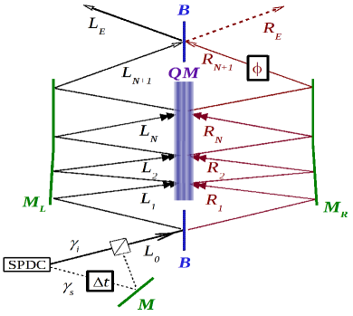
We consider a Michelson-Morley interferometer in which the central, two-sided mirror is quantum delocalized in the direction, perpendicular to its reflecting surfaces Kippenberg and Vahala (2008); Marquardt and Girvin (2009); Aspelmeyer and Schwab (2008), see Fig. 1. The quantum mirror’s wave function is described by its center-of-mass density matrix for which we want to assume that it has a coherent extension of a few tens of nanometers (this might, for example, be achieved through a ballistic expansion of a tightly squeezed and cooled mirror Corbitt et al. (2007)
which is suddenly set free Steuernagel (2011)).
In the first step of the entrainment procedure a single photon , such as those available from spontaneous parametric down-conversion (SPDC) pair-creation processes Hong et al. (1987), is sent through the interferometer, entering, say, through port .
In a classical interferometer, using a sharply localized perfect mirror, the phase-shifter can be set such that this photon will exit through port with certainty since destructive interference renders port dark. With a sufficiently widely delocalized central mirror, however, this interference pattern gets washed out and photons will exit through port as well.
We want to concentrate on one photon at-a-time arrangements, the next photon should interact with the mirror after the previous has passed. The delay time between any two photons is therefore constrained by
| (1) |
here 100 fs is the photons’ coherence time Hong et al. (1987) and the distance they travel between two mirror interactions. Note that for single bounce setups (; compare Fig. 1) the interaction time for photons is thus bound by and we can generate and interrogate a momentum-superposition state repeatedly on the picosecond timescale. This is in marked contrast to the “standard approach” of confining the light inside a cavity Marshall et al. (2003); Vitali et al. (2007); Huang and Agarwal (2009); Jähne et al. (2009).
For the formal analysis we need to determine the bosonic light-field operators and at the exit ports in terms of those at the entrance ports and (we will leave empty, see Fig. 1)
| (2) |
The unitary 22 matrices , , and describe balanced mirrors, photon propagators, and kick operators, respectively. Specifically, is a special case of a lossless splitter with reflection probability , namely
| (3) |
The photon propagators
| (4) |
account for the path length of mode “” including the phase jump due to the reflection by the perfect mirrors and , respectively.
The kick operators enact the partial reflection and transmission of photons by the quantum mirror in conjunction with the associated momentum transfer to its center-of-mass density matrix :
| (5) |
With an angle of incidence the effective photon momentum transfer is , where is their wave number and the kick operators in Eq. (5) have the form
| (6) | |||||
| (7) |
The initial density matrix of the system (quantum mirror plus light field) is
| (8) |
We will from now on assume that only single photons are present at a time (i.e., and ). The determination of photon numbers at an output port of the interferometer involves tracing out the quantum mirror and projecting onto that port (here, )
| (9) |
Tracing over the field yields an effective kick operator acting on the mirror’s density matrix . For example, for the setup of Fig. 1 with a single bounce off the mirror () and assuming a photon enters through path and is found to exit through port we have (with normal incidence )
| (10) | |||||
For simplicity we write , then, similarly, .
According to Eq. (1) the time of interaction between all successive photons and the mirror are very short, all reference to the time evolution of the mirror is therefore absent in our expressions for .
Since the quantum mirror’s density matrix changes in response to the port in which the exiting photon is detected, we represent the history associated with varying experimental outcomes through a multi-index, namely, we write down the ports or in which the exiting photons are registered:
| (11) | |||||
for example, describes the mirror’s density matrix when the fourth photon is seen in the left port after the first two were detected there as well, but the third exited to the right.
The initial mirror density matrix is normalized: , this is not true for density matrices conditioned on measurements. Only all conditional density matrices taken together are normalized since, for , we have
| (12) |
in other words, the integrated conditional density matrices carry the relative weights for the occurrence of certain experimental outcomes: . Here is the history label which denotes the occurrence of a specific run, such as , in example (11). We are thus led to define the momentary spatial mirror probability density
| (13) |
which, when integrated over, yields the probability to observe a photon exiting through port given a particular history
| (14) |
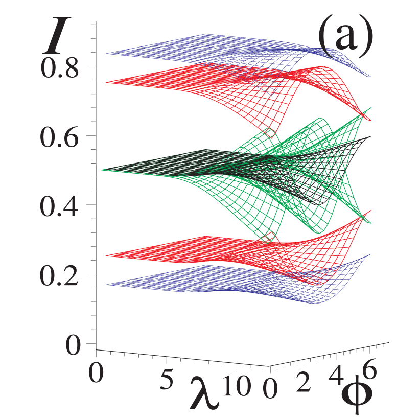
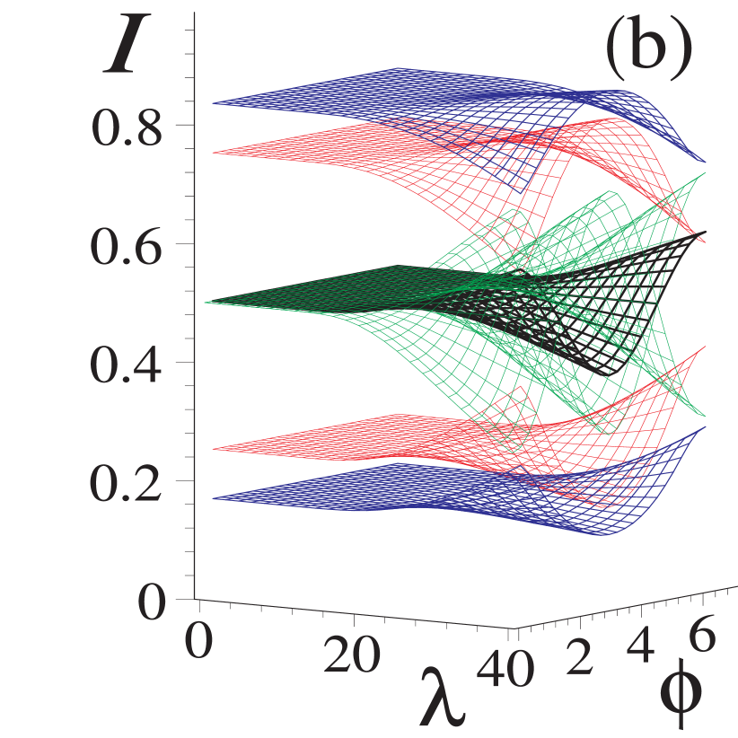
Since the kick operators depend on wavelength and phase setting , the intensity does as well, compare Fig. 2. Obviously , and for single-photon at-a-time scenarios equals the photon intensity of Eq. (9).
The effective spatial wavelength for imprint and interrogation can be determined from eq. (10) and is
| (15) |
where the form factor for a top hat and roughly 1.5 for a Gaussian wave packet, this is best seen in Fig. 2 (b). This shrinkage of the effective imprint and interrogation wavelength is noteworthy, compare plots in Figs. 2 and 3.
The above kick factors are special cases of the general back-action a photon imparts onto its scatterer. Typically its back-action destroys coherence Steuernagel and Paul (1995), but here the interferometer geometrically restricts the photons to two (incoming and two reflected) modes only. We therefore end up with the desirable kick factors that represent controlled, quantum-superposed momentum kicks. This allows us to create momentum superposition states from initially stationary quantum mirror states and allows for their detection and reinforcement through entrainment.
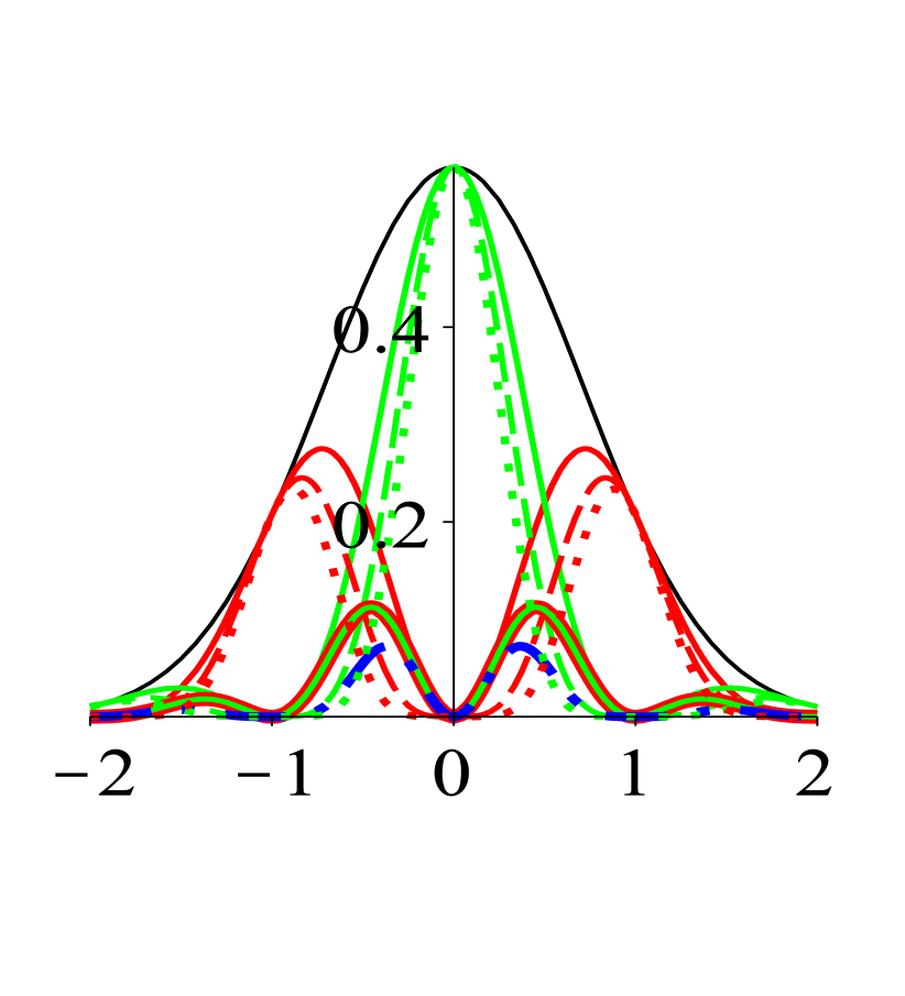
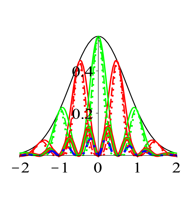
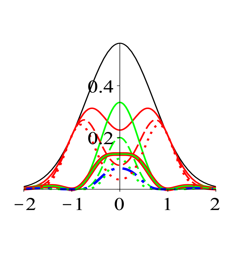
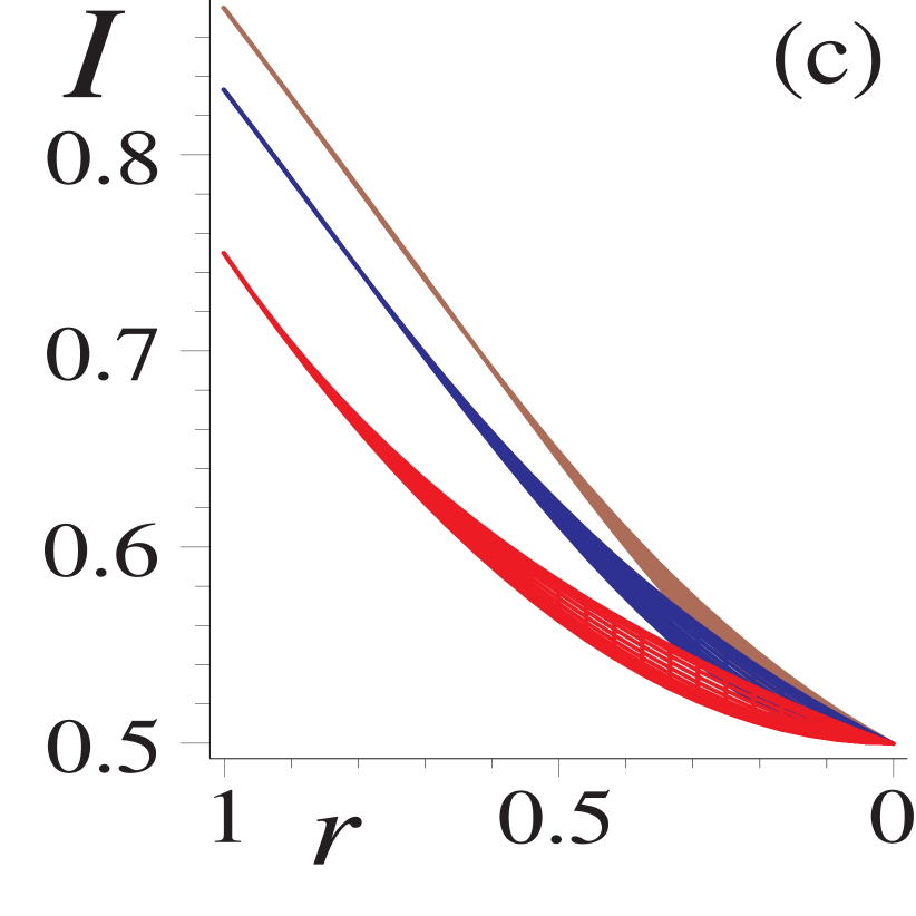
For a sufficiently wide mirror wave function we end up with sine- or cosine-shaped imprint patterns for or respectively. Hence, and become approximately orthogonal wave functions, a second photon picks up this trace and tends to follow the first photon. This happens with roughly a 75% : 25% bias, see Fig. 2, the system has thus become entrained. The second photon’s detection moreover imprints the same kick factor onto the mirror’s center-of-mass wave function thus reinforcing this trend. The third and fourth photons follow their predecessors with an increasing bias of roughly 83% and 87%, respectively, see Fig. 2 (c). Each time, the mirror gets kicked in an identical fashion this procedure reinforces the interference fringes.
It should probably be emphasized that the sine- or cosine-shaped imprint patterns are to be interpreted as our increase in knowledge about the localization of the mirror according to classical wave optics. Without further a priori information about the nature of the initial state of the mirror the method presented here does not allow us to infer that an interference imprint has been created or detected. The method works for any kind of mixed state and is therefore fairly insensitive to temperature- and other effects, such as non-zero average center-of-mass velocities and displacements of the average center-of-mass position of the quantum mirror, as long as .
The rapidity of this method and the fact that it only probes the mirror at chosen points in time reduces its contribution to decoherence. For mirrors initially in sufficiently widely spread-out pure states the back-action imprints and detects interference imprints. An interrogation-photon’s arrival time can be delayed to allow for the investigation of the quantum mirror’s time evolution and its decoherence.
All features discussed above prevail for imperfect mirrors even when their reflectivity drops to 60% or less, see Figs. 2 (c) and 3 (c).
To conclude: An analysis of free photons interacting with a quantum-delocalized mirror inside an interferometer shows that their recoil can create and investigate momentum superposition states of massive objects non-destructively, within a picosecond. The analysis makes use of the entrainment of following photons by their predecessors. Such entrainment may well turn out to be a useful new response mode of quantum systems in various settings.
References
- Heisenberg (1927) W. Heisenberg, Zeitschrift für Physik 43, 172 (1927).
- Björk et al. (1999) G. Björk, J. Söderholm, A. Trifonov, T. Tsegaye, and A. Karlsson, Phys. Rev. A 60, 1874 (1999), eprint 9904069.
- Kippenberg and Vahala (2008) T. J. Kippenberg and K. J. Vahala, Science 321, 1172 (2008).
- Braginsky and Khalili (1992) V. B. Braginsky and F. Y. Khalili, Quantum measurement (Cambridge Univ. Press, Cambridge, 1992).
- Zurek (2003) W. H. Zurek, Rev. Mod. Phys. 75, 715 (2003).
- Rau et al. (2003) A. V. Rau, J. A. Dunningham, and K. Burnett, Science 301, 1081 (2003).
- Dunningham et al. (2004) J. A. Dunningham, A. V. Rau, and K. Burnett, J. Mod. Opt. 51, 2323 (2004).
- Cable et al. (2005) H. Cable, P. L. Knight, and T. Rudolph, Phys. Rev. A 71, 042107 (2005), eprint 0411167.
- Douglas and Burnett (2011) J. S. Douglas and K. Burnett, Localization and entanglement through scattering measurements (2011), eprint 1109.0041.
- Marquardt and Girvin (2009) F. Marquardt and S. M. Girvin, Physics 2, 40 (2009).
- Aspelmeyer and Schwab (2008) M. Aspelmeyer and K. Schwab, New J. Phys. 10, 095001 (2008).
- Corbitt et al. (2007) T. Corbitt, Y. Chen, E. Innerhofer, H. Müller-Ebhardt, D. Ottaway, H. Rehbein, D. Sigg, S. Whitcomb, C. Wipf, and N. Mavalvala, Phys. Rev. Lett. 98, 150802 (2007).
- Steuernagel (2011) O. Steuernagel, Time Evolution of Harmonic Oscillator Thermal Momentum Superposition States (2011), eprint 1109.1818.
- Hong et al. (1987) C. K. Hong, Z. Y. Ou, and L. Mandel, Phys. Rev. Lett. 59, 2044 (1987).
- Marshall et al. (2003) W. Marshall, C. Simon, R. Penrose, and D. Bouwmeester, Phys. Rev. Lett. 91, 130401 (2003).
- Vitali et al. (2007) D. Vitali, S. Gigan, A. Ferreira, H. R. Böhm, P. Tombesi, A. Guerreiro, V. Vedral, A. Zeilinger, and M. Aspelmeyer, Phys. Rev. Lett. 98, 030405 (2007).
- Huang and Agarwal (2009) S. Huang and G. S. Agarwal, Phys. Rev. A 79, 013821 (2009), eprint 0810.2589.
- Jähne et al. (2009) K. Jähne, C. Genes, K. Hammerer, M. Wallquist, E. S. Polzik, and P. Zoller, Phys. Rev. A 79, 063819 (2009), eprint 0904.1306.
- Steuernagel and Paul (1995) O. Steuernagel and H. Paul, Phys. Rev. A 52, R905 (1995).