Pulling and Pushing a Cargo With a Catalytically Active Carrier
Abstract
Catalytically active particles suspended in a liquid can move due to self-phoresis by generating solute gradients via chemical reactions of the solvent occurring at parts of their surface. Such particles can be used as carriers at the micro-scale. As a simple model for a carrier-cargo system we consider a catalytically active particle connected by a thin rigid rod to a catalytically inert cargo particle. We show that the velocity of the composite strongly depends on the relative orientation of the carrier-cargo link. Accordingly, there is an optimal configuration for the linkage. The subtlety of such carriers is underscored by the observation that a spherical particle completely covered by catalyst, which is motionless when isolated, acts as a carrier once attached to a cargo.
pacs:
89.20.-a, 82.70.Dd, 07.10.CmIntroduction. The increasing interest in the development of “lab on a chip” devices has led to a stringent need of scaling standard machinery down to micro- and nano-scales. This reduction in size has raised a number of challenging issues, such as to endow small objects with the capacity to perform autonomous, directional motion Whitesides_2002 ; Paxton_review_2006 ; Lauga_2009 ; Howse_review_2010 . Towards this goal two main routes are pursued. The first one consists of designing artificial mechanical “swimmers” by mimicking the sophisticated locomotion strategies of natural micro-organisms such as E. Coli or Spiroplasma (see, e.g., Refs. Lauga_2009 ; Cheang_2010 and references therein). The second approach consists of transforming chemical free energy into mechanical work by employing phoretic mechanisms, i.e., motion induced by interfacial interactions Paxton_review_2006 ; Howse_review_2010 . In the following we focus on this latter approach.
Several proposals for such catalytic self-propellers have already been tested experimentally (see, e.g., Refs. Whitesides_2002 ; Paxton_2004 ; Sen_2005 ; Howse_2007 ; Leiderer_2008 ; Sanchez_2009 and Refs. Paxton_review_2006 ; Howse_review_2010 for reviews). The underlying idea Whitesides_2002 is that an asymmetric decoration of the surface of a particle with a catalyst, which promotes an activated reaction in the surrounding liquid medium, leads to a non-uniform distribution of product molecules around the surface of the particle. This non-uniform distribution gives rise to particle motion through a variety of mechanisms Whitesides_2002 ; Paxton_2004 ; Howse_2007 ; Sanchez_2009 . When the size of the particle is decreased towards the micron scale or below, viscous and surface forces start to dominate and inertia-based mechanisms such as bubble ejection propulsion become ineffective Lauga_2009 . (However, alternative propulsion mechanisms based on bubble formation can remain active, as for the catalytically active tubes proposed in Ref. Sanchez_2009 .) If the product molecules remain dissolved in the surrounding liquid medium, concentration gradients develop along the surface of the particle. It has therefore been argued Paxton_2004 ; Golestanian_2005 that in such cases the motion of the catalyst-covered active particle is phoretic, i.e., it results from the interfacial interactions between the particle and the non-uniformly distributed product molecules generated by the chemical reaction. Recent experimental Paxton_2004 ; Paxton_2005 ; Paxton_review_2006 ; Howse_2007 ; Leiderer_2008 ; Sanchez_2009 ; Boquet_2010 , simulation Kapral_2007 ; Lowen_2010 , and theoretical Golestanian_2005 ; Golestanian_2007 ; Prost_2009 ; Popescu_2009 ; Popescu_2010 ; Boquet_2010 ; Lowen_2010 studies of such systems have contributed to a significantly improved understanding of this self-induced phoresis of isolated active particles.
One of the envisioned applications of such self-propellers is to use them as active carriers for colloidal transport and assembly Sen_2008 ; Sanchez_2009 . While in classic phoresis Derjaguin_1966 ; Anderson_1989 the concentration gradients are externally imposed and maintained, for self-phoresis the gradients are dynamically generated by the catalytic reaction occurring on parts of the particle surface. The interplay between these concentration gradients and the ensuing hydrodynamic flows not only powers the phoretic motion of such active particles, but also influences the effective interaction among each other, with nearby inert particles, or with bounding walls Golestanian_2007 ; Popescu_2009 . Accordingly, the performance of such active particles as carriers is expected to depend strongly on these effective interactions.
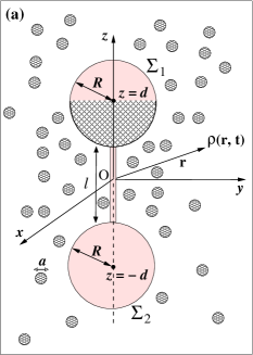
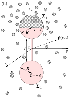
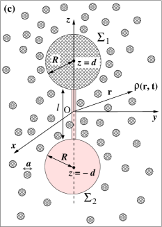
Here we study a simple model for the transport of an inert particle, posing as a cargo, by an active diffusio-phoretic carrier 111“Diffusio-phoresis” is restricted here to phoresis in gradients of electrically neutral solutes (often also denoted as “chemo-phoresis”).. The model consists of two spherical particles, with the surface of one of them partially covered by a catalyst and being connected by a thin rigid rod. Similar to previous studies Golestanian_2005 ; Golestanian_2007 ; Popescu_2009 ; Popescu_2010 ; Prost_2009 , we adopt the standard theory of diffusio-phoresis Derjaguin_1966 ; Anderson_1989 and derive, within the constraints of this approach Popescu_2009 , the velocity of the carrier-cargo composite for two distinct orientations of the link [see Figs. 1(a)-(b)]. The results show that the performance of the carrier, i.e., the resulting velocity of the composite system, strongly depends on the orientation of the link, which is a paradigmatic consequence of the self-phoresis mechanism of the motion. As an extreme case we study how a spherical particle, which is completely covered by catalyst and thus is unable to move on its own, can act as a carrier once it is attached to a cargo [see Fig. 1(c)]. We note that the emergence of motion in this latter case can be intuitively understood by realizing that in the limit of a very short linkage this configuration is equivalent with the so-called dimer model of an active particle Kapral_2007 .
Model. The system we consider is shown and characterized in Fig. 1. We assume a uniform distribution, with the areal density , of the catalyst over a hemisphere of the carrier particle. The infinitesimal thin rod enforces that there is no relative motion between the carrier and the cargo. Furthermore, the rod is aligned such that the carrier-cargo composite possesses axial symmetry. The co-moving coordinate system has its direction along the axis of symmetry and the plane is the midplane between the two spheres. If the carrier is partially covered by catalyst, there are two possible configurations with axial symmetry: the active area of the carrier points towards [Fig. 1(a)] or away from [Fig. 1(b)] the cargo. For this system the only possible motion is a translation along the -direction. The purpose of these simplifications is to sift out the main phenomena of interest, i.e., the dependence of the self-phoretic velocity on the internal orientation of the carrier-cargo system and, for the configuration shown in Fig. 1(c) (which can be seen as a dimer model like in Ref. Kapral_2007 ), the emergence of motion solely from linking together an otherwise motionless active particle with an inert cargo.
The catalyst promotes the chemical conversion of the solvent surrounding the composite system into product molecules. Here we focus on the particular case in which the chemical conversion of a solvent molecule () leads to two product molecules ( and ) only, one with properties and size being similar to the solvent itself (), the other one () being significantly different 222It has been argued that this is approximately the case for the Pt catalyzed decomposition in aqueous solution of hydrogen peroxide ( = H2O2) into water ( = H2O) and oxygen ( = O2) Golestanian_2005 ; Howse_2007 ; Howse_review_2010 ; Popescu_2010 . . Accordingly, in the following only this latter one is denoted as a product molecule and plays the role of a solute in the solvent. The product molecules of diameter diffuse into the solvent characterized by a diffusion coefficient . Thus the net result of the chemical conversion can be viewed approximately as the generation of a solute only by an ensemble of independent sources uniformly distributed over a part of the carrier surface. The reaction rate at such a catalytic site, i.e., the number of product molecules created at that site per unit time , is assumed to be independent of time. The number density of product molecules is considered to be so low that among themselves they behave like an ideal gas. However, there is an interaction potential between the product molecules and the moving particle, which, inter alia, realizes the impermeability condition at the particle surface. The interactions between the product molecules and the solvent are accounted for effectively via the Stokes - Einstein expression S-E_relation , where is the Boltzmann constant, is the temperature, and is the viscosity of the solution (i.e., solvent plus solute).
The direct and the solvent mediated particle-solute interactions combined with the non-uniform distribution of the solute, created at the catalyst covered region, lead to an unbalanced osmotic pressure along the surface of the particle which induces flow of the solvent Derjaguin_1966 ; Anderson_1989 ; Golestanian_2005 ; Ajdari_2006 ; Prost_2009 ; Popescu_2009 and motion of the particle. For micrometer-size particles typical self-phoretic velocities are of the order of m/s. Accordingly, both the Reynolds number (where is the mass density of the solvent, the linear extension of the particle, and the velocity of the translational or rotational motion) and the Peclet number are small Happel_book . Thus the hydrodynamic description approximately reduces to the Stokes equations and the convection of the solute can be disregarded compared with its diffusive transport.
Phoretic slip. The effective interactions between the particles and the self-generated, asymmetric, non-uniform solute number density around the particles Derjaguin_1966 ; Anderson_1989 ; Golestanian_2007 have a typical range , which is comparable with the solute diameter , and induce flow of the solution relative to the particle. In steady state this hydrodynamic flow in the thin surface layer is accounted for by a (phoretic) slip-velocity Derjaguin_1966 ; Anderson_1989 ,
| (1) |
where is a point on the surface of the particles and denotes the projection of the gradient operator onto the corresponding local tangential plane of the surface of the particles 333 Rigorously, Eq. (1) should be interpreted as a condition on the outer edge of the surface layer. For the outer problem this can be replaced by because varies over length scales which are much larger than .. This serves as a boundary condition for the hydrodynamic flow in the outer region, i.e., outside the surface layer Anderson_1989 ; Golestanian_2007 ; Popescu_2009 . The mobility coefficient is determined by the aforementioned effective interaction potential and by the hydrodynamic boundary condition (stick or slip) on the surface of the particle, which is the inner edge of the surface layer Anderson_1989 ; Ajdari_2006 . For simplicity, here we take to be constant over the whole surface . We note that correspond to repulsive and attractive effective interactions, respectively Popescu_2009 ; Anderson_1989 .
Distribution of product molecules. In the limit of small Peclet numbers and neglecting any so-called polarization effects of the surface layer Anderson_1989 , the steady state distribution of product molecules in the outer region around the two moving particles is governed, in the co-moving frame, by the diffusion equation
| (2) |
This is subject to the boundary conditions (BCs)
| (3a) | |||
| (3b) |
Equation (3b), where corresponds to the reaction rate per unit area and denotes the outward direction normal to the surface, describes how the catalytic reaction at translates into a source of product particles Golestanian_2007 ; Popescu_2010 .
Hydrodynamic flow outside the surface layer. Because there are no forces acting on the solution beyond the surface layer, based on the assumption of low Reynolds numbers the hydrodynamic flow field in the outer region is obtained as the solution of force free and incompressible Stokes equations:
| (4) |
is the corresponding pressure tensor, where is the hydrostatic pressure and is the shear stress tensor, i.e., . In the comoving reference frame, attached to the carrier-cargo composite which is moving with relative to the solution, which is quiescent far away, these equations are subject to the BCs of a flow velocity far away () from the composite and at the outer edge of the surface layer. This corresponds to sticking at the surface of the particles plus a slip velocity at the outer edge of the surface layer:
| (5) |
Equation (5) reveals that the cargo plays an active role ( on ) despite being catalytically inert.
Phoretic velocity. After computing the hydrodynamic flow in the outer region, which depends parametrically on the translation of the two particles via the BCs in Eq. (5), the phoretic velocity is determined by the condition that the motion of the system composed of the particles plus their surface layers is force free Anderson_1989 .
Equations (2) and (3) as well as Eqs. (4) and (5) are most conveniently solved in terms of bispherical coordinates Reed_1976 ; Jeffery_1912 ; Jeffery_1926 ; Arfken_book
| (6) |
where ; the corresponding scale factors , , and are given by
| (7) |
The choice ensures that the family of spheres includes the ones, , corresponding to the surfaces of the carrier and the cargo, respectively. Noting that the intersection of an iso-surface with a iso-surface is a circle parallel to the plane and that the equatorial circle parallel to the plane on corresponds to , the area covered by the catalyst is parametrized by , and for the configuration in Fig. 1(a), for the one in Fig. 1(b), and for the one in Fig. 1(c).
In terms of bispherical coordinates the solution of Eq. (2), which does not depend on due to the axial symmetry of the system, which is finite at (i.e., on the axis), and which satisfies the BC in Eq. (3a), can be written as Reed_1976 ; Jeffery_1912
| (8) |
where denotes the Legendre polynomial of order and is a density scale chosen such that the system specific parameters are factored out from the boundary conditions [Eqs. 3]. Noting that on and expanding the right hand side of Eq. (3b) in a series of Legendre polynomials, the BCs in Eq. (3b) determine the coefficients as the solution of a system of linear equations. This determines and the slip velocity follows from with .
Due to the linearity of the Stokes equations the hydrodynamic flow field [Eqs. (4) and (5)] is the superposition of the one corresponding to with stick BCs on and the one corresponding to a quiescent flow far away, i.e., = 0 with slip BCs on . The solution for the first problem is known Jeffery_1926 and corresponds to a hydrodynamic force on the composite , where
| (9) |
The second solution for the flow field is most conveniently expressed in terms of the Stokes stream function for axisymmetric flows [which in cylindrical coordinates is defined by ]. In terms of bispherical coordinates is given by Jeffery_1926
| (10) |
where
| (11) |
Jeffery_1926 is formally denoted as the Gegenbauer polynomial of degree and order Brenner_1961 , and the characteristic velocity is chosen such that the system dependent parameters are factored out from the boundary conditions in Eq. (5). Because there are no flow sources or sinks along the -axis, we require the stream function to vanish there Happel_book , i.e., . Since for , but as a linear function cannot be zero for both , this constraint implies that the term is removed from the series representation in Eq. (10).
In terms of the stream function, the boundary condition of a vanishing flow velocity along the direction normal to the surfaces (corresponding to impenetrability) leads to the requirement Happel_book , which can be shown to be equivalent to the simpler form Happel_book ; Brenner_1961 . The flow velocity along the slip direction is given in terms of the stream function by Happel_book which, according to Eq. (5), on the surfaces should be equal to the phoretic slip . Since for and the polynomials are orthogonal, , the coefficients can be determined from these boundary conditions on in terms of by solving a system of linear equations 444In practice, the infinite system has to be truncated at a certain order . For our system it turns out that both and vanish rapidly upon increasing . In all cases studied, at these coefficients are smaller than , compared with values of the order of unity for . This behavior is sufficient for the convergence of the velocity expression in Eq. (12).. The hydrodynamic force acting in the positive -direction on the composite due to this second flow is given by Jeffery_1926 .
Requiring that the total force acting on the composite vanishes Derjaguin_1966 ; Anderson_1989 thus leads to the following expression for the velocity:
| (12) |
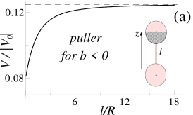
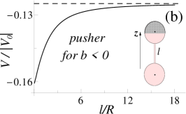
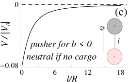
Discussion. In Fig. 2 we show the velocity of the carrier-cargo system as a function of the scaled length of the linkage in the range for the three configurations considered in Fig. 1 in the case of repulsive effective interactions between the product molecules and the material forming the carrier-cargo system, i.e., for and . (The calculations can easily be extended to , but: (i) the implicit assumptions of a homogeneous solvent and point-like product molecules are expected to break down for very small separations, which renders Eq. (12) to be inapplicable for too small values of , and (ii) the limiting configuration corresponding to carrier and cargo being in contact merely reduces to the case of self-diffusiophoresis of a single particle with a complex shape.)
For the choice the carrier alone moves against the gradient of product molecule along its surface. Therefore the configurations in Figs. 1 (a) and (b) correspond to a pulling and a pushing carrier, respectively. Focusing first on the configurations in Figs. 2 (a) and (b), we note that the pusher or puller character is maintained at all separations , i.e., the velocity of the composite is always along the positive and negative direction in the cases (a) and (b), respectively. In all cases, for the velocity shows a significant dependence on the separation , which clearly indicates that the cargo plays actually an active role in the resulting motion of the composite. In both cases at large separations the velocity approaches limiting values seemingly equal to , respectively, which is of the velocity at which the active carrier half-covered by catalyst would move if isolated Popescu_2010 . However, the pusher slows down upon increasing whereas the puller speeds up. Therefore, for any length of the linkage the pusher configuration exhibits a faster motion than the puller one. These findings can be rationalized intuitively as follows. For example, in the case (a) the generation of product molecules by the carrier induces also a concentration gradient around the cargo surface pointing in the direction opposite to the one on the carrier surface. Consequently, the cargo behaves also like an active particle and induces a hydrodynamic flow around its surface in the direction opposite to the one around the carrier, which thus leads to a smaller net hydrodynamic flow and accordingly to a slower motion of the composite.
Any other orientation of the carrier-cargo link breaks the axial symmetry, inducing a rotation of the composite in addition to its translation; this leads to a reduction in the translational velocity. Therefore the pusher configuration [Fig. 1 (b)] is the optimal (i.e., maximal velocity) configuration if the effective interaction between the product molecules and the carrier-cargo material is repulsive. On the other hand, if this effective interaction is attractive () the same intuitive arguments as above lead to the conclusion that the puller and pusher characters are interchanged between the configurations shown in Fig. 1(a) and (b), while the -dependence of the velocity changes signs. Therefore, for attractive effective interactions the puller configuration [Fig. 1 (b)] is the optimal one.
The motion of active particles is known to be affected by thermal fluctuations, and thus its directionality only holds over time scales smaller than the characteristic rotational diffusion time, crossing over to Brownian motion at longer time scales Golestanian_2007 ; Golestanian_2009 . Inspecting the cases of the carrier-cargo configurations shown in Figs. 1 (a) and (b), one realizes that in (a) the cargo has a stronger influence than in (b) on the stability of the composite with respect to such fluctuations of the direction of motion. For , in the case of the puller [Fig. 1 (a)] a sudden change in direction producing a tilt of the symmetry axis towards the left relative to the O axis breaks the axial symmetry of the product concentration profile, and larger concentrations occur to the right of the symmetry axis. Consequently, right after the change in direction the cargo is driven through a region where the concentration of the product particles is larger on its right half (relative to the cargo-carrier axis) and thus induces a torque on the cargo and a rotation of the symmetry axis back towards the O direction. Therefore, in the puller configuration the cargo tends to stabilize the directionality of motion against thermal fluctuations. On the other hand, in the pusher configuration [Fig. 1 (b)] the cargo is further away from the source of product particles. Therefore it is basically insensitive to such changes in the symmetry of the product concentration distribution as it moves away from it and consequently no significant restoring torques occur.
Configuration (c) reveals the rather peculiar consequence of self-phoretic propulsion that a carrier, which in isolation would be motionless, is activated by being linked to an otherwise inert cargo. This occurs because the linkage provides the anisotropy needed for self-phoresis to become operational Paxton_2004 ; Golestanian_2005 . For short links, the velocity of such a composite is significant. According to Fig. 2, for , is approximately 1/3 of the largest possible velocity of an isolated spherical active carrier. For repulsive (attractive) effective interactions the inert cargo turns the neutral carrier into a pusher (puller). We note that for lengths the carrier-cargo system in configuration (c) becomes similar to the geometry of the so-called dimer model of an active colloid which, for an catalytic reaction, has been proposed and investigated with Molecular Dynamics simulations Kapral_2007 .
The diffusiophoresis mechanism and the geometry of the model have been chosen with the intention to provide clear examples which reveal and underscore the complexity of such active carrier - cargo systems. We note that the main influence of the inert cargo stems from the fact that the nearby chemically active colloid gives rise to concentration gradients, and thus to phoretic slip velocity, along its surface, too. This is very different from the cases discussed in Ref. swimmers_2008 , where hydrodynamic interactions between dimer swimmers are ”rectifying” the otherwise reciprocal movement of each of two dimers, and thus are leading to the emergence of collective and relative motion. We anticipate a rather rich behavior to emerge as various model constraints are relaxed, such as: (i) Different effective interactions between the product molecules and the cargo and carrier material, i.e., different mobility factors (of potentially opposite sign) on the carrier and cargo surfaces, will lead to a complex dependence of the velocity on the orientation of the linkage. (For example, in the case shown in Fig. 2(a) with of opposite sign the velocity can change sign as is increased.) (ii) In the case of charged active particles and charged reaction products, the motion will be determined by the interplay of self-diffusiophoresis and self-electrophoresis, which amplifies the roles played by the orientation of the linkage and by the surface properties of the cargo and carrier. (iii) A convex or concave shape of the surface of the cargo facing the carrier side leads to a possible amplification or reduction, respectively, of the concentration gradients around the carrier and the cargo. This list can be extended, but it already now shows that employing active particles as carriers allows an exceptional flexibility in the design of cargo-carrier systems, which should be very beneficial for potential applications.
References
- (1) R.F. Ismagilov, A. Schwartz, N. Bowden, and G.M. Whitesides, Angew. Chem., Int. Ed. 41, 652 (2002).
- (2) W.E. Paxton, S. Sundararajan, T.E. Mallouk, and A. Sen, Angew. Chem., Int. Ed. 45, 5420 (2006).
- (3) E. Lauga and T.R. Powers, Rep. Prog. Phys. 72, 096601 (2009).
- (4) S.J. Ebbens and J.R. Howse, Soft Matter 6, 726 (2010).
- (5) U. Kei Cheang, D. Roy, J.H. Lee, and M.J. Kim, Appl. Phys. Lett. 97, 213704 (2010).
- (6) W.E. Paxton, K.C. Kistler, C.C. Olmeda, A. Sen, S.K.St. Angelo, Y. Cao, T.E. Mallouk, P.E. Lammert, and V.H. Crespi, J. Am. Chem. Soc. 126, 13424 (2004).
- (7) J.M. Catchmark, S. Subramanian, and A. Sen, Small 1, 1 (2005).
- (8) J.R. Howse, R.A.L. Jones, A.J. Ryan, T. Gough, R. Vafabakhsh, and R. Golestanian, Phys. Rev. Lett. 99, 048102 (2007).
- (9) A. Erbe, M. Zientara, L. Baraban, C. Kreidler, and P. Leiderer, J. Phys.: Condens. Matter 20, 404215 (2008).
- (10) A.A. Solovev, Y.F. Mei, E.B. Ureña, G. Huang, and O.G. Schmidt, Small 5, 1688 (2009); S. Sanchez, A.A. Solovev, Y.F. Mei, and O.G. Schmidt, J. Am. Chem. Soc. 132, 13144 (2010).
- (11) R. Golestanian, T.B. Liverpool, and A. Ajdari, Phys. Rev. Lett. 94, 220801 (2005).
- (12) W.E. Paxton, A. Sen, and T.E. Mallouk, Chem. Eur. J. 11, 6462 (2005).
- (13) J. Palacci, C. Cottin-Bizonne, C. Ybert, and L. Bocquet, Phys. Rev. Lett. 105, 088304 (2010).
- (14) B. ten Hagen, S. van Teeffelen, and H. Löwen, J. Phys.: Condens. Matter 23, 194119 (2011).
- (15) G. Rückner and R. Kapral, Phys. Rev. Lett. 98, 150603 (2007); L.F. Valadares, Y.-G. Tao, N.S. Zacharia, V. Kitaev, F. Galembeck, R. Kapral, and G.A. Ozin, Small 7, 565 (2010).
- (16) R. Golestanian, T.B. Liverpool, and A. Ajdari, New J. Phys. 9, 126 (2007).
- (17) F. Jülicher and J. Prost, Eur. Phys. J. E 29, 27 (2009).
- (18) M.N. Popescu, S. Dietrich, and G. Oshanin, J. Chem. Phys. 130, 194702 (2009).
- (19) M.N. Popescu, S. Dietrich, M. Tasinkevych, and J. Ralston, Eur. Phys. J. E 31, 351 (2010).
- (20) S. Sundararajan, P.E. Lammert, A.W. Zudans, V.H. Crespi, and A. Sen, Nano Lett. 8, 1271 (2008).
- (21) B.V. Derjaguin, Yu.I. Yalamov, and A.I. Storozhilova, J. Colloid Interface Sci. 22, 117 (1966).
- (22) J.L. Anderson, Ann. Rev. Fluid Mech. 21, 61 (1989).
- (23) A. Einstein, “On the Movement of Small Particles Suspended in a Stationary Liquid Demanded by the Molecular-Kinetic Theory of Heat” in Investigations on the theory of the Brownian motion, edited by R. Fürth, transl. by A. D. Cowper (Dover, New York, 1956), p. 12.
- (24) A. Ajdari and L. Bocquet, Phys. Rev. Lett. 96, 186102 (2006).
- (25) J. Happel and H. Brenner, Low Reynolds number hydrodynamics (Noordhoff International, Leyden, 1973), Chapt. 3-5, pp. 85-87; Chapt. 5, pp. 96-107.
- (26) L.D. Reed and F.A. Morrison Jr., J. Colloid Interface Sci. 54, 117 (1976).
- (27) G.B. Jeffery, Proc. R. Soc. London A 87, 109 (1912).
- (28) M. Stimson and G.B. Jeffery, Proc. R. Soc. London A 111, 110 (1926).
- (29) G. Arfken, Mathematical Methods for Physicists, 2nd ed. (Academic, Orlando, 1970), Chapt. 2.14, pp. 115-117.
- (30) H. Brenner, Chem. Eng. Sci. 16, 242 (1961).
- (31) R. Golestanian, Phys. Rev. Lett. 102, 188305 (2009).
- (32) G.P. Alexander and J.M. Yeomanas, Europhys. Lett. 83, 34006 (2008); E. Lauga and D. Bartolo, Phys. Rev. E 78, 030901(R) (2008).