EURONU-WP6-11-32
IFIC/11-22
Short-baseline Neutrino Oscillation Waves in Ultra-large Liquid Scintillator Detectors
Sanjib Kumar Agarwalla111Email: Sanjib.Agarwalla@ific.uv.es, J.M. Conrad222Email: conrad@mit.edu, M.H. Shaevitz333Email: shaevitz@nevis.columbia.edu
Instituto de Física Corpuscular, CSIC-Universitat de València,
Apartado de Correos 22085, E-46071 Valencia, Spain
22footnotemark: 2Department of Physics, Massachusetts Institute of Technology,
Cambridge, Massachusetts 02139, USA
33footnotemark: 3Department of Physics, Columbia University, New York,
New York 10027, USA
Abstract
Powerful new multi-kiloton liquid scintillator neutrino detectors, including NOA and LENA, will come on-line within the next decade. When these are coupled with a modest-power decay-at-rest (DAR) neutrino source at short-baseline, these detectors can decisively address the recent ambiguous signals for neutrino oscillations at high . These detectors are 50 m long, and so with a DAR beam, the characteristic oscillation wave will be apparent over the length of the detector, providing a powerful verification of the oscillation phenomena. LENA can simultaneously perform appearance and disappearance searches with unprecedented sensitivity. NOA is likely limited to disappearance given its present design, but also has excellent sensitivity in the high region. For the appearance channel, LENA could provide a stringent test of the LSND and MiniBooNE signal regions at with a reduced fiducial volume of 5 kt and a 10 kW neutrino source. In addition, the LENA and NOA disappearance sensitivities in mode are complementary to the recent reactor anomaly indicating possible disappearance and would cover this possible oscillation signal at the level.
1 Introduction
Recent results from short-baseline (SBL) neutrino oscillation studies seem to point towards the existence of sterile neutrinos. The strongest indication comes from the LSND experiment [1, 2, 3, 4], which has reported a excess of events in a beam of . The associated of the assumed oscillation is too large to be explained with only three active neutrinos, and so oscillations involving sterile neutrinos are invoked which do not couple to W and Z bosons. The LSND result is supported by an apparent excess of events in a beam of above observed in MiniBooNE [5]. This result is consistent with two-neutrino oscillations at 99.4% confidence level.
More motivation has arisen from a recent reanalysis of the expected flux emitted from nuclear reactors [6] that leads to an observed deficit of at 98.6% C.L. The reactor anti-neutrino flux prediction depends on accurate prediction of the reactor isotopes produced as a function of time convoluted with the spectra of anti-neutrinos produced by each isotope [7]. This anomaly arises from new calculations of the second ingredient, the anti-neutrino spectra, that update analyses from the 1980’s [8, 9, 10] by including the latest information from nuclear databases and improving the calculational techniques [6]. The overall reduction in predicted flux compared to the existing data from SBL neutrino experiments can be interpreted as oscillations at baselines of order 10–100 m [11] consistent with the LSND and MiniBooNE anti-neutrino results which require a mass squared difference of the order 0.1–10 eV2.
The SBL experimental results can be described using models which involve three active and one sterile (3+1) or two sterile (3+2) neutrinos [12, 13, 14, 15, 16, 17, 18, 19, 20, 21], with relatively small mixing to the active flavors, allowing for oscillations with high . While a sterile neutrino is theoretically well motivated with a large number of phenomenological consequences, the actual oscillation parameters required by the LSND and MiniBooNE anti-neutrino data are in conflict with various constraints imposed by other SBL neutrino oscillation experiments, most notably CDHS [22], MiniBooNE disappearance measurements [23] and also the data from reactor experiments, like Bugey [24]. Also, there is no sign of sterile oscillations in atmospheric and solar neutrino data in the required parameter range [18]. This tension could be relieved by fitting neutrino and anti-neutrino results separately [25], suggesting that neutrinos might oscillate differently than anti-neutrinos. When analyzed within the context of the recent reactor anti-neutrino anomaly, a low, but acceptable, compatibility is found in the global fit using a (3+2) model [26]. The oscillation parameters found in these fits have eV2 associated with the sterile neutrino oscillations
In the next five years, a series of small experiments will explore the (3+1) and (3+2) signal space further. This program includes continued MiniBooNE running in anti-neutrino mode and running of the MicroBooNE Experiment in neutrino mode [27]. Also, the upcoming KATRIN beta decay experiment is sensitive to a light sterile neutrino [28]. The Low Energy Neutrino Spectroscopy (LENS) detector, which is now in the prototype stage, may also run with radioactive neutrino sources in order to explore the question of sterile neutrinos [29, 30]. However, none of these experiments are expected to provide confirmation at the 5 confidence level in the near future.
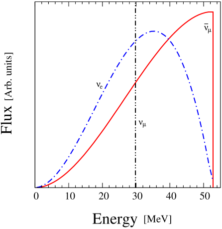
The next major step in the search for SBL oscillations can be achieved by pairing one of the ultra-large liquid scintillator detectors planned for the near future with a low energy neutrino beam. These experiments can study and oscillations. The high-sensitivity disappearance search will bring unique information to the fits for comparison to the reactor disappearance results. A relatively low power neutrino source producing neutrinos via the pion decay-at-rest (DAR) chain, is ideal. The DAR chain leads to a beam dominated by neutrinos between 20 and 52 MeV, with a well-defined flavor content of , and , as shown in Fig. 1. This source may be provided by a low energy proton accelerator with a beam impinging on a target/dump. Potentially, this can be a prototype for the cyclotrons planned for the DAEALUS -violation search [31, 32, 33]. This would be a small, relatively inexpensive proton source which can be easily positioned within 20 m of the detectors.
The energy range of the DAR beam is well suited to observe the dependence of the oscillation wave across the length scales of presently planned detectors. A precise search for appearance and disappearance oscillations can be achieved by fitting the observed events with respect to expectation as a function of . Besides observing oscillations from a simple counting analysis, these types of experiments also will confirm that oscillations are taking place by seeing the variations within the detector. For a 40 MeV neutrino energy and = 2 eV2, the characteristic oscillation length is 50 m which matches with the length of the liquid scintillator detectors being proposed for the near-future program. Because of the 1/ falloff of the neutrino flux with distance, the part of the detector within 50 m of the DAR source provides the main oscillation search sensitivity. Therefore, maintaining at least 50 m of detector length near the source appears to be best for covering the oscillation space of interest.
In this paper, we consider two examples of scintillator detectors. Our example of an unsegmented detector is LENA [34], under consideration within the LAGUNA [35] project and the forthcoming LAGUNA-LBNO [36] design studies. The conclusions should be similar for other unsegmented detectors such as Hanohano[37, 38]. Our example of a finely segmented detector is NOA [39], which is under construction for long-baseline studies using a beam from Fermilab. This detector is found to be less powerful than LENA, but has the advantage that it is already under construction and has an ideal space for the neutrino source. Each of these experiments can be used as designed, with only the addition of the beam source.
We note that the large liquid scintillator detectors represent one of three types of future neutrino detectors under discussion. The other two types of detectors are water and liquid argon (LAr) based detectors. Ref. [40] provides an initial exploration of SBL oscillation searches using a DAR neutrino beam and the existing Super-Kamiokande detector with the addition of Gadolinium. The opportunities for an LAr detector will be explored in [41].
This paper is organized as follows. We begin with the description of neutrino source and DAR flux in Sec. 2. In Sec. 3, we deal with the relevant SBL neutrino oscillation probabilities. After that, we describe the characteristics of liquid scintillator detectors (NOA and LENA) in detail in Sec. 4. We also discuss the possible charged current (CC) interactions of a DAR beam in liquid scintillator. In Sec. 5, we present our results for sterile oscillation searches using DAR-LENA and DAR-NOA setups. We summarize and draw our conclusions in Sec. 6.
2 The Neutrino Source and DAR Flux
| per year, per flavor (, and ), |
| per year of ( compared to other flavors); |
| Delivered as 100 kW average power, with 200 kW instantaneous power, |
| (50% duty factor allowing equal beam-on and beam-off data sets); |
| 800 MeV protons on target; |
| 25 cm smearing (assumed flat) on neutrino production point; |
| 20 m distance from average production point to face of detector fiducial region. |
In a stopped pion source a proton beam of GeV energy interacts in a low-A target producing and, at a low level, mesons. The pions then are brought to rest in a high-A beam stop. The will capture. The will produce the following cascade of decays
resulting in , and , but no , as shown in Fig. 1. The resulting flux is isotropic.
Certain choices of proton beam kinetic energy and neutrino beam stop design are crucial to producing the purest, highest rate DAR flux [42, 43]. As discussed in Ref. [33], the production of DAR neutrinos is relatively flat and maximized in the region of beam kinetic energy 700 to 1500 MeV for a given beam power. Selecting the lower energy range reduces the production, which has a threshold of 602 MeV. Above 1500 MeV, kaon production is above threshold. It is for this reason that high energy proton beams, such as the 3 GeV beam proposed for Project X [44], are poor sources for a DAR beam. The most efficient DAR production is on a light target which has tightly bound neutrons. In high-A targets, energy is wasted in neutron production [45]. High-A targets also have increased production compared to light targets [46]. For this reason, a spallation neutron source, which uses high-A targets for neutron production, is not an ideal venue for the kind of experiments described here. In the optimized DAR beam designs, the light target for production is typically embedded in a high-A, dense material. This increases the probability that the produced in the light target will be captured before decay-in-flight (DIF), minimizing the decay chain that produces backgrounds. Upstream targets, as are used in neutron production and also for isotope production, must not be used for this study, because these will substantially increase DIF backgrounds [3]. As a model of a DAR source, we use the DAEALUS design [33].
The DAEALUS accelerators are cyclotrons [47, 48, 49], an ideal low-cost source for low energy (800 MeV) protons. The one caveat to the use of a cyclotron as the accelerator is that the bunch spacing is typically a few tens of nanoseconds (e.g. one DAEALUS design operates at 66 MHz [49]), hence much smaller than the muon lifetime. As a result these machines effectively operate as a continuous source (often called a “CW” source). It is straightforward to run this CW beam for milliseconds and then turn the beam off; however, implementing shorter spills is costly. DAEALUS designs typically run the beam for 100 ms periods. The required long spill precludes use of beam-timing to identify flavors, as has been suggested for DAR studies at spallation sources that employ expensive linacs and buncher rings [50, 51, 52].
The DAEALUS accelerators are being designed to produce more than 1 MW average power. The instantaneous power is a product of the energy and current of the protons on target, while the average power also accounts for the duty factor. The DAEALUS power needs are driven by the multi-kilometer distances required for the -violation search. The extracted beam is defocussed and the carbon target has a tapered entrance to spread the beam, to allow high instantaneous power on target. In order to cycle between sites and to allow for beam off running, the DAEALUS experiment employs 10% to 20% duty factors. This leads to high instantaneous power requirements that are not needed in the SBL experiments we describe here.
As will be shown in Sec. 5, an average beam power of 100 kW is sufficient to achieve most goals. We propose to allow some beam-off periods so that cosmogenic backgrounds can be measured and subtracted. A reasonable run-plan could have a 50% duty factor with a 200 kW instantaneous power on the target, delivered with the same time structure as planned for DAEALUS. Table 1 provides an overview of the assumptions used for the calculations in Sec. 5, unless otherwise noted. The low power requirement, with similar time structure to DAEALUS, would make these accelerators ideal as prototypes for the high-power DAEALUS machines.
The position of the neutrino production point depends on the proton interaction length in the target material, the pion stopping length in the target, and shielding and tapering of the target entrance to spread the beam power. We will assume a cm smearing for the neutrino production point in this study. We take this to be flat in , which is an overestimate of the smearing. We also assume that, on average, neutrinos are produced 20 m from the detector face to allow for accelerator shielding. We assume DAEALUS-level contamination, which is at of the in the beam.
While the ratio of flavors and the energy dependence of the flux are well understood in a DAR flux, the overall normalization is not well predicted. The dominant error comes mainly from the uncertainty on the pion production per proton on target [46, 42, 43]. We assume a 10% correlated normalization error on all flavors, which is slightly more conservative than in [46, 42, 43]. We also assume a 20% error on the DIF background [3].
3 (3+n) sterile neutrino oscillation hypotheses
If one assumes CPT invariance and no matter effects, then the probability for a neutrino produced with flavor and energy , to be detected as a neutrino of flavor after traveling a distance , is [53, 54]:
| (1) | |||||
where and denote the real and imaginary parts of the product of mixing matrix elements, respectively. In Eq. 1, , or , ( being the sterile flavor); ( being the number of sterile neutrino species). The neutrino mass splitting is given by in . The dependence associated with oscillations appears within the term , where is in m and is in MeV. The represent the elements of the mixing matrix that connects the mass to the flavor eigenstates. For anti-neutrinos, the oscillation probability follows Eq. 1 with the replacement of with its complex-conjugate matrix. Therefore, if the elements of the mixing matrix are not real, neutrino and anti-neutrino oscillation probabilities are not identical. Imaginary parameters enter the mixing matrix through -phases, which, in turn, lead to differences in the neutrino versus anti-neutrino oscillation probability.
In a (3+2) model, two sterile neutrinos are added at the eV scale with the three active neutrinos. In the SBL approximation where the largest mass-splittings dominate and , following Eq. 1, the appearance oscillation probability is given by
| (2) | |||||
where is the -phase. We use this expression to estimate the signal event rates for appearance studies (see Sec. 5) in (3+2) models for the best fit parameter values as given in Table 2. We can see that the probability in Eq. 2 depends on two independent mass splittings (, ) and on the combinations and . Therefore, including , the total number of independent parameters in this channel is 5.
In a (3+1) model with only one sterile neutrino, Eq. 2 takes the form
| (3) |
where is the effective mixing angle. One can see that -phase does not appear in the (3+1) case.
Again following Eq. 1 with the SBL approximation, the disappearance oscillation probability in a (3+2) model can be written as
| (4) | |||||
which we use to simulate the survived event rates in (3+2) models. In this channel, we have 4 independent parameters.
In a (3+1) model, Eq. 4 simplifies to
| (5) |
where is the defining mixing angle for SBL electron neutrino disappearance.
| A : Ref. [26] | 0.47 | 0.128 | 0.165 | 0.87 | 0.138 | 0.148 | 1.64 |
| B : Ref. [25] | 0.39 | 0.40 | 0.20 | 1.10 | 0.21 | 0.14 | 1.1 |
4 Liquid Scintillator Detectors
Scintillating–oil detectors use well understood technologies, but the planned next steps involve significant increases in scale. Segmented scintillator detectors have been traditionally used for GeV-scale experiments. The largest pure-scintillator, finely-segmented example is the 170t ton BNL 734 experiment [55]. On the other hand, KamLAND [56] and Borexino [57] have demonstrated ton-scale unsegmented liquid scintillator detectors, with the latter demonstrating a very low level of background, allowing low-energy ( 1 MeV) neutrino studies with low systematics.
The next generation of these detectors are more than an order of magnitude larger than those described above. NOA, which is under construction at Ash River, Minnesota, US, is a segmented detector. This detector will come on-line in 2013 [58]. LENA, which is an unsegmented, very-low background detector, is proposed for the LAGUNA [35] project in Europe. Because site-selection for LAGUNA is only just underway, this detector will come online later than NOA, around 2020.
Both NOA and LENA are intended for long baseline oscillation studies. The SBL running does not conflict with the long baseline running for several reasons. First, the long baseline neutrino beam has energies MeV, producing events that are easy to separate from the lower energy DAR events. Second, the long baseline beam timing allows one to gate out the DAR beam for a few milliseconds around the the long-baseline few-microsecond spill.
4.1 DAR beam interactions in liquid scintillator oil
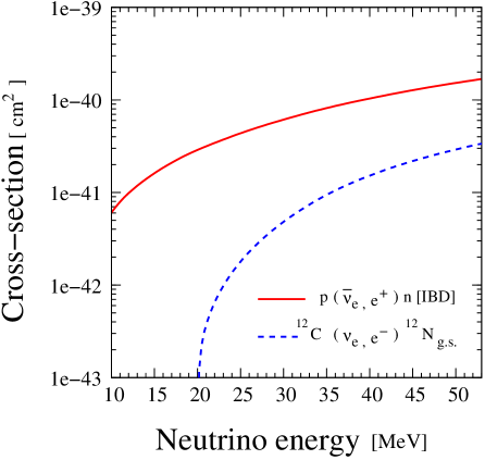
As discussed above, a DAR beam consists of , , with a small admixture of with energies ranging up to 52.8 MeV. Because of the low beam energy, a muon cannot be produced in a CC interaction. Therefore, detectors with oil-based targets (CHn) are limited to observe CC interactions involving the electron flavor scattering. Inverse -decay, (IBD), [59] is the golden channel for these detectors to detect the appearance of . This process has a very low kinematic threshold of 1.81 MeV and provides a very useful delayed coincidence tag between the prompt positron and the delayed neutron capture by a proton, (2.2 MeV) after an average time of 250 s.
Another CC reaction that we consider is C Ng.s. [60] with a relatively high kinematic threshold of 17.33 MeV. This process is used to perform the disappearance searches using . In this cross-section, we only consider the contribution coming from the transition to the 12N ground state, which can be identified by the detection of the prompt electron, followed within a 60 ms window by the positron from the beta decay of the 12Ng.s. with a mean lifetime of 15.9 ms. The cross section for this exclusive reaction 12C(, e-)12Ng.s. is well measured compared to the inclusive cross-section for transitions to excited states of 12N and has an error of 5 to 10% [60]. Probably the contribution from transitions to excited states of 12N can also be used and would increase the event rate by about 30 to 40%. The excited state cross-sections are less well known but since the power of the measurements presented here mainly comes from an shape analysis, these uncertainties are not very important.
Fig. 2 shows the cross sections both of the CC flavor selective processes used in this study. The cross section for C B compared to that for IBD scattering is sufficiently low to be neglected from these studies. We also do not consider the neutrino-electron scattering interaction because the rates are two orders of magnitude lower than the rate of 12C scattering.
| Detector | NOA Far | LENA |
| Characteristics | Detector | |
| Shape | Rectangular | Cylindrical |
| Fiducial Mass | ||
| Overburden | 3 m earth-equivalent | 1450 m of rock/4060 mwe |
| @ Pyhäsalmi | ||
| Solvent | LAB () | |
| Neutrino Energy | (Dis) | (App) |
| Threshold | (Dis) | |
| Detection Efficiency | 50% (Dis) | 90% (App) |
| 80% (Dis) | ||
| Energy Resolution, | 15% [61] | 10% [62] |
| in units of | ||
| Signal error (syst.) | 20% (Dis) | 10% (App) |
| 15% (Dis) | ||
| Background error (syst.) | 5% [Non-beam] (Dis) | 20% [Intrinsic , ] (App) |
| – |
4.2 A Finely-Segmented Detector: NOA
NOA [39] is a segmented, scintillator detector constructed for long baseline neutrino oscillation studies around 2 GeV, which is 40 times higher in energy than the DAR events. Because this detector is not designed for 50 MeV events, it is not ideal for the studies we present here. Nevertheless, we show that NOA has the capability to produce significant disappearance results with a few years of DAR beam running.
NOA consists of PVC cells filled with scintillator oil, assembled into a m3 detector. The scintillator is mineral oil base doped with 4.1% pseudocumene [1,2,4-Trimethybenzene]. The PVC structure (CHCHCl), which is dead region, represents 30% of the 14 kt fiducial mass. For simplicity, we assume that the target as entirely CH2 for this analysis. Individual cells are 3.9 cm high 6.0 cm along the beam direction 15.5 m long transversely and are glued in and planes. The orientation of the planes alternates throughout the detector.
Light produced in the scintillator is absorbed and re-emitted with wavelength shifting (to 550 nm) optical fibers. These run the length of the PVC cell and double back to readout APDs. The APDs have a rather high noise rate but will be cooled to reduce the noise to be below the cosmic-ray muon rate. The attenuation length of the fiber is roughly the same as the 15 m length of the cells. Triggering requires at least one 1 hit in adjacent and planes. The detector is below ground level with overburden shielding of 3m of earth. This modest shielding leads to a 20 kHz rate of through-going and 1 kHz of stopping muons [61] in the detector.
The NOA setup is ideal for the proposed cyclotron-dump design. The cyclotron can be located on the surface, allowing easy maintenance, while the target/dump can be located in an open area of the detector hall which is used for staging and not needed after the detector is constructed. The incoming beam will impinge on a target embedded in the dump. Targeting the beam perpendicular to the detector direction is an extra precaution against DIF backgrounds. In addition, the 50 m length of the detector is appropriate for neutrino oscillation measurements with 20 to 50 MeV neutrinos probing the eV2 region.
We expect that the shielding around the dump will lead to a very low fast neutron background. Because the detector staging area is quite large, it will be possible to add up to 10 m of extra shielding, if required. Beyond this, the detector is self-shielding. Therefore we do not expect a significant fast neutron background from the cyclotrons. It is for this reason that we can place the face of the detector at 20 m from the center of the target. A summary of the assumptions we make about the NOA detector in the analyses is given in Table 3.
The fine segmentation of the detector allows determination of the vertex to a few cm. As a result, the smearing in the measured value will be dominated by the uncertainty in the neutrino production point for which we use a cm flat distribution.
The disappearance study makes use of C Ng.s. interaction with a visible reconstruction energy threshold of 20 MeV which corresponds to a neutrino energy threshold of 38 MeV. This threshold significantly reduces the accepted flux for the measurements, as seen in Fig. 1 but still gives about 34k events per year (see Sec. 5). We assume 50% efficiency for this process.
The scatters will be reconstructed along the 67 m length of the detector, allowing the oscillation wave to be fit as a function of . Since the target nucleus is much heavier than the outgoing electron, the incident neutrino energy is simply related to the the visible outgoing electron energy independent of the scattering angle. The electron energy resolution is listed in Table 3.
The largest background source will be from the Michel electrons/year produced by stopped muon decay. These are produced with nearly the same energy dependence as the electrons from CC scatters. The Michel electron events can be identified and vetoed by tracking the parent muon. The entire target can be used to identify muons before a candidate scattering event, which may require that a substantial part of the upper region of the target be used for this veto. In the analysis presented in the following section, we consider a range of veto capabilities giving from 10,000 to 50,000 total un-vetoed Michel background events per year. We also show the no-background case for reference. We assume that the 50% beam-off running can measure this background with a 5% error in each bin.
In principle, the NOA detector can also tag events through the coincidence signal of the positron light followed by light from the 2.2 MeV photon emitted in the neutron capture on H. In practice, observation of the the neutron-capture signal in NOA will be quite difficult. First, the signal from the 2.2 MeV is diffuse, being produced by electrons from multiple Compton scatters. Because the NOA detector has 30% dead material, there is a high probability that a substantial fraction of the 2.2 MeV energy deposit will be unobserved. Second, the attenuation length of the wavelength shifting fibers is on the scale of the 15 m length of the scintillator tubes. Thus, the detector is highly inefficient for very low light deposits. Third, the false coincidences with comic muon produced background may be very high in a surface detector. These are complex analysis issues that would require further study to quantify and we therefore choose not to present the appearance capability of NOA in this paper.
4.3 An Unsegmented Detector: LENA
The LENA (Low Energy Neutrino Astronomy) detector [34] is optimized for low energy neutrino detection. The experiment is specifically designed for state-of-the-art measurements of supernova neutrinos (bursts and diffuse), which are in the same energy range as DAR flux, and solar neutrinos, geoneutrinos, and reactor neutrinos, all of which are an order of magnitude lower in energy. As a result, this detector is substantially more powerful than NOA for the DAR-based SBL program we consider here.
The low energy neutrino studies require substantial shielding of at least 4000 mwe. The search for a possible underground site for LENA has been performed in the framework of the LAGUNA design study [35]. Two possible choices are Pyhäsalmi and Fréjus. Both the sites have rock shielding 4000 mwe resulting a very low rates of through-going muons, at the level of Hz/m2 [34]. The stopping muon background rate is negligible. The rate of atmospheric electron neutrino interactions in the DAR energy range will also be negligible. Nevertheless, we assume that there will be 50% beam-off running. This allows cross-checks of the backgrounds as well as allowing the simultaneous data-taking for the supernova and SBL studies.
The LENA detector is planned to be 100 m in length and 30 m in diameter. If a fiducial volume of 13.6 m radius is chosen, then the detector will contain 50 kt of liquid scintillator while the outside region will be filled with water to act as a veto for muons and shield for neutrons. The detector will have 30% coverage from a combination of direct photocathode coverage and light concentrators.
In the studies below, we also consider several smaller fiducial volumes. None are in the present LENA plans. However, a 5 to 10 kt prototype may be attractive along the path to LENA and pressure at the base of the detector on the PMTs may lead preferance for a 25 kt design. Therefore, we also include these possibilities in our discussion.
Both CC 12C events for disappearance and IBD scattering events for appearance can be used in the analysis. For LENA, we consider LAB solvent () with free protons and carbon nuclei in a 50 kt detector. Demonstration that oil can be purified well below the levels required for the SBL physics come from the KamLAND [56] and Borexino [57] experiments. The specific assumptions about the LENA detector relevant to this study appear in Table 3.
The arrangement of the cyclotron and target/dump will be designed after the location of the detector is established. Tunnel access where the neutrino source can be moved into the detector region is most attractive. We assume that the neutrino source will be located on the long-axis of the cylinder and will be 20 m away from the cylinder surface.
LENA can explore both appearance and disappearance oscillations. The signals are the same as discussed for NOA: and C Ng.s., respectively. Because the detector is designed for excellent reconstruction of geoneutrinos and astrophysical signals at 2 MeV, there is high efficiency for reconstructing the 2.2 MeV neutron capture . We consider 90% detection efficiency for appearance studies and 80% efficiency for disappearance, although this is likely to be very conservative. Vertex reconstruction can be expected to have a 5 cm uncertainty [34]. This is negligible on the scale of the 25 cm uncertainty from the neutrino source.
We assume that there is very little background in LENA. The mwe shielding reduces the cosmic ray background to a negligible level. The next largest natural background is from atmospheric neutrinos. These are at the 1% level for the 100 kW source. It should be noted that the atmospheric muon neutrino background is much lower than in a water Cerenkov detector. This is because, in a scintillation detector, all muons from charged current events are identified, whereas in the water detector some are below Cerenkov threshold. We assume a m wall of undisturbed rock (or equivalent steel or concrete shielding) in the design that will reduce beam backgrounds from neutrons produced at the accelerator to a negligible level at the detector. The additional water shielding further protects the detector.
Disappearance searches proceed in the same manner as NOA. The signal is the variation of C Ng.s. across the length of the detector. For the oscillation sensitivity estimates, the simulated data, taking into account the detector energy resolution and the neutrino source position smearing, are binned according to energy and position in 65 equally sized bins. A visible energy cut of 16 MeV is imposed for the events, which corresponds to a 33 MeV cut on the incoming neutrino energy. This visible energy cut will practically eliminate backgrounds from atmospheric and reactor neutrinos as well as environmental radioactivity. Normalization is included but because these errors are large, the fits are dominated by the shape dependence.
LENA is designed also to have high efficiency for (IBD) events at neutrino energies in the 10 to 50 MeV range identified by a delayed coincidence between the outgoing positron and capture of the neutron. This is the signal for diffuse supernova neutrinos, and an important process for supernova burst events – both of which are key physics goals of LENA. Thus, LENA is specifically designed for lower energies in contrast to NOA. Using the IBD events, LENA can make a very precise search for appearance by again binning and fitting events as a function reconstructed . For our studies, the visible energy threshold is set to 19 MeV corresponding to a neutrino energy cut of 20 MeV. Again, this requirement will reduce the non-beam backgrounds to negligible level.
This puts LENA in a unique position to measure both appearance and disappearance in the same detector through the characteristic change in the oscillation wave with . That would be a very powerful signal in support of sterile neutrino models and offers the best opportunity to disentangle (3+1) from (3+2) oscillations.
5 Results
In this section, we first discuss SBL appearance with LENA. This is key to confirming or refuting the LSND [1, 2, 3, 4] and MiniBooNE [5] anti-neutrino results. Then we focus on SBL disappearance studies with LENA and NOA, which are complementary searches to the reactor anomaly disappearance signal [11, 6].
5.1 Appearance Mode
| Fiducial Mass | Radius | Length | Signal | Signal | Intrinsic |
| (A : Ref. [26]) | (B : Ref. [25]) | Background | |||
| 50 kt | 13.58 m | 100 m | 12985 | 32646 | 1450 |
| 25 kt | 10.78 m | 79.37 m | 7787 | 18356 | 875 |
| 10 kt | 7.94 m | 58.48 m | 3753 | 7964 | 443 |
| 5 kt | 6.3 m | 46.42 m | 2080 | 4044 | 261 |
The LENA appearance search uses the IBD signal. Following Ref. [34], we consider a cylindrical unsegmented liquid-scintillator detector of 50 kt fiducial mass with 100 m in length and 13.58 m in radius as a reference choice. We also study the impact of smaller-sized LENA type detectors with fiducial masses of 25, 10 and 5 kt. In all cases, we keep the fractional photodetector coverage and aspect ratio (length/diameter) same as we consider for 50 kt. In addition, while varying the fiducial mass of the detector, we keep the detector characteristics unchanged as described in Table 3. The main source of background is the intrinsic beam contamination from decays (see Table 1), because cosmogenic backgrounds are very low (see Sec. 4.3). The neutrino energy threshold for this analysis is which renders potential backgrounds coming from supernova and radioactive decay negligible. We present all our results assuming a flat resolution on the neutrino length distribution of 25 cm dominated by the uncertainty in the neutrino production point.
In Table 4 we present the signal and intrinsic background event rates in 5 to 50 kt LENA type detector including the source and the detector characteristics as shown in Table 1 and 3 respectively. In column 4 and 5, the signal events have been estimated for two different sets of parameter values in (3+2) model as given in Table 2. Here we consider a total neutrino flux of from DAR beam. One should note that the number of signal events does not increase linearly with the fiducial mass because of the geometry of the detector and the isotropic nature of the flux. While increasing the fiducial mass from 5 to 50 kt, the length of the detector increases by a factor of 2.15 and since the source is located on the axis of the cylinder and 20 m away from the beginning of the detector, a very small amount of neutrinos reach the ends of the detector due to the 1/ suppression from the isotropic source.
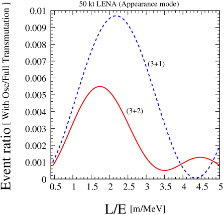
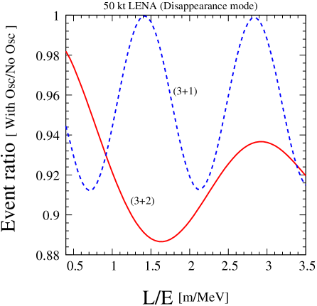
With a source-to-detector-face distance of 20 m, the accessible L range in 50 kt detector is 20 - 120 m and with an energy range of 20 - 52.8 MeV in DAR beam, the -dependence of the oscillation pattern can be well observed inside the detector. This is illustrated in Fig. 3, where in each reconstructed bin, we show the ratio of signal events for a given set of oscillation parameter values to the number of events computed assuming a hypothetical case where the oscillation probability is one. This has been done just to demonstrate the oscillation pattern inside the detector as a function of reconstructed for a particular set of parameter values. The red solid line corresponds to the parameter values in the (3+2) model as given in the upper row of Table 2, denoted by A. The blue dashed line has been drawn for the (3+1) best fit values ( = 0.57 eV2 and = 0.0097) obtained using LSND, MiniBooNE anti-neutrino and KARMEN [63] data sets in [25]. As one can see from Fig. 3, the demonstration of the oscillation wave is dramatic in the long LENA detector and can provide a powerful handle to discriminate between (3+1) and (3+2) schemes.
For our statistical analysis, we bin our signal and background events into 94 equally sized bins and consider uncorrelated normalization errors on the signal and intrinsic background of 10% and 20% respectively. These uncertainties are fully correlated between the bins and are included in the analysis using the pull-term method as described in e.g. Ref. [64, 65]. For the fitting, we perform the usual analysis using a Poissonian likelihood function.
In Table 5 we present the amount of flux needed for a 5 to 50 kt LENA type detector to exclude the two different sets of oscillation parameter values in the (3+2) scheme as given in Table 2. The numbers presented here for CL (5 dof) under the assumption that we have only intrinsic beam background. We can immediately see that with a very modest flux and a small size LENA detector, we can check these test points at high significance. This also shows that the dependence is very important for rejecting the background and therefore reducing the sensitivity to systematic errors. The ability to observe the dependence is crucial if a signal is observed, since it will allow one to establish or refute oscillations as the underlying physics explanation.
| Fiducial Mass | Flux | Flux |
|---|---|---|
| (A : Ref. [26]) | (B : Ref. [25]) | |
| 50 kt | ||
| 25 kt | ||
| 10 kt | ||
| 5 kt |
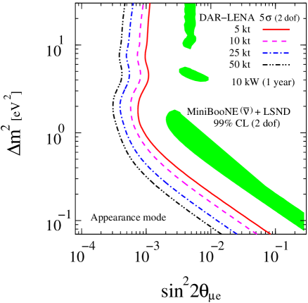
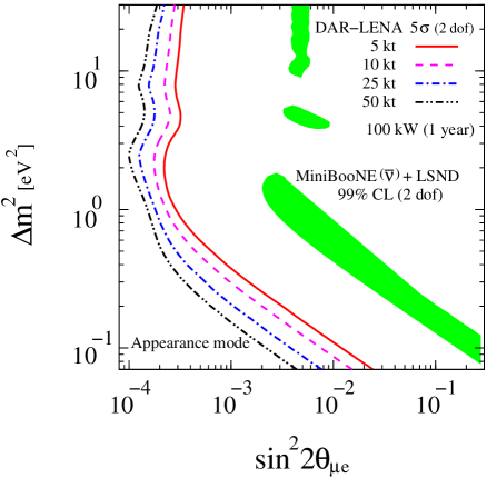
Fig. 4 presents the sensitivity limit of the DAR-LENA setup to sterile neutrinos in the (3+1) model at 5 confidence level (2 dof) using the appearance mode. We compare our results with the allowed region at 99% CL (2 dof) from a combined analysis of the LSND and MiniBooNE anti-neutrino signals [26]. The results are presented for four different choices of the fiducial mass of the detector. The left panel shows the sensitivity for which can be achieved in one year with a small 10 kW average power machine. The right panel exhibits the same for our reference choice of 100 kW machine. It can be seen from the left panel that a 5 kt LENA type detector and a one year run at 10 kW average power is more than sufficient to exclude the parameter space suggested by the combined fit of LSND and MiniBooNE anti-neutrino data at 5 CL. Note, that the sensitivity is limited by the magnitude of the beam background and therefore does not improve linearly with the size of the detector. In the right panel, the 50 kt detector has a reach up to = 0.0001 at = 2 eV2 with .
5.2 Disappearance Mode
| Fiducial Mass | Radius | Length | Evts w/ Osc | Evts w/ Osc | Evts, No Osc |
| (A : Ref. [26]) | (B : Ref. [25]) | ||||
| 50 kt | 13.58 m | 100 m | 170191 | 139119 | 181672 |
| 25 kt | 10.78 m | 79.37 m | 102726 | 85271 | 109590 |
| 10 kt | 7.94 m | 58.48 m | 52105 | 43940 | 55439 |
| 5 kt | 6.3 m | 46.42 m | 30874 | 26321 | 32735 |
| Fiducial | Length | Breadth | Height | Evts w/ Osc | Evts w/ Osc | Evts, No Osc |
| Mass | (A : Ref. [26]) | (B : Ref. [25]) | ||||
| 14 kt | 67 m | 15.7 m | 15.7 m | 32388 | 27407 | 34415 |
Both LENA and NOA offer the possibility to study oscillations to sterile neutrinos in the disappearance mode by using the CC reactions of on 12C. In Table 6 we present the total number of CC scattering events on 12C in 5 to 50 kt LENA type detectors using the information on the source and the detector characteristics from Table 1 and 3 respectively. Column 4 and 5 show the number of survived events after oscillation using the two different sets of (3+2) parameter values given in Table 2. The last column shows the total event rate without any oscillation. Here we have used total flux of with a neutrino energy threshold of 33 MeV and an efficiency of 80%. Table 7 shows the same for the 14 kt NOA far detector but with a neutrino energy threshold of 38 MeV and an efficiency of 50%. We can expect thirty-four thousand events in NOA with no oscillation considering only the contribution of the transition of 12C to the 12N ground state [60]. From Table 6 we can see that the impact of disappearance on the total event rate is 6.3%/23.4% for the A/B parameter sets in the 50 kt LENA detector. One should note that this is not a mere counting experiment and that the pattern of the oscillations provides most of the measurement sensitivity. This can be seen in Fig. 5 where we plot the ratio of events with and without sterile oscillation as a function of the reconstructed in the 50 kt LENA detector. With an L range of 20 - 120 m and with an energy range of 33 - 52.8 MeV, the -dependence of the oscillation pattern can be well observed inside the detector. The solid red line is for the oscillation parameter values in the (3+2) model as given in the upper row of Table 2. The blue dashed line shows the results for the (3+1) best fit values: = 1.78 eV2 and = 0.089 obtained from reactor anti-neutrino data with the new predictions for the reactor flux [26]. As seen in Fig.5, the shapes are quite different for (3+1) and (3+2) waves. Also, a comparison between the amplitudes of the wave in various bins cancels flux normalization and background systematic uncertainties to a large extent.
| Fiducial Mass | Flux | Flux |
|---|---|---|
| (A : Ref. [26]) | (B : Ref. [25]) | |
| 50 kt | ||
| 25 kt | ||
| 10 kt | ||
| 5 kt |
| Total | Flux | Flux |
|---|---|---|
| Background | (A : Ref. [26]) | (B : Ref. [25]) |
| 50000 | ||
| 25000 | ||
| 10000 | ||
| 0 |
In Table 8 we present the amount of flux that is needed in 5 to 50 kt LENA type detectors to exclude the two different sets of oscillation parameter values in the (3+2) scheme as given in Table 2. The results are presented at CL (4 dof) under the assumption that there are no beam or non-beam backgrounds for LENA disappearance search (see Sec. 4.3). In this analysis, we consider 15% systematic error on the signal and we follow the same numerical method used for the appearance results. Table 8 shows that the required amount of flux is highly dependent on the choice of the parameter values rather than the detector size. For example, we need 26 times more flux for the parameter set A compared to B in the 25 kt LENA option. In Table 9, we present the results for NOA considering a 20% systematic error on signal and a 5% systematic error on Michel decay backgrounds as measured during beam-off running. From this table, one can see the impact of the different choices of effective background on the required flux as compared to the no-background case.
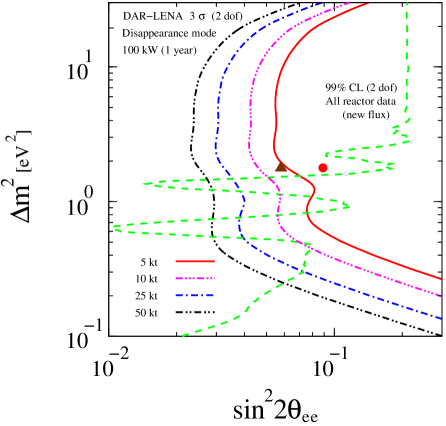
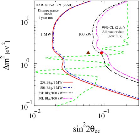
In Fig. 6 we show the sensitivity limit of the DAR-LENA setup to sterile neutrinos in a (3+1) model at 3 CL (2 dof) using the disappearance channel. We compare our results with the 99% CL (2 dof) limit from reactor anti-neutrino data with the new reactor fluxes [66]. The triangle ( = 1.78 eV2 and = 0.058) and the bullet ( = 1.78 eV2 and = 0.089) show the (3+1) best-fit values of all reactor data with the old and new fluxes respectively. These are shown as benchmark points to judge the performance of the LENA setup. A 10 kt LENA with a flux of is sufficient to cover these test points and can provide stringent test of the recent reactor anomaly with high significance. Fig. 7 shows the sensitivity limit of the DAR-NOA setup to sterile neutrinos in a (3+1) model. Again, results are presented at 3 CL (2 dof) for the disappearance mode. We show the results considering 25000 and 50000 effective Michel electron backgrounds with (100 kW) and (1 MW) total fluxes. For NOA, a 100 kW machine is marginal in covering the test points and a higher-power, full DAEALUS type machine, is needed to cover the entire parameter space. By comparing Fig. 6 and Fig. 7, one can say that a 14 kt NOA with 10 times larger flux can give similar performance as to a 50 kt LENA with a reference flux of .
6 Summary and Conclusions
A host of recent SBL neutrino oscillation experiments have provided hints that there may be oscillations to sterile neutrinos with a mass squared difference of the order 0.1–10 eV2. Sterile neutrino models involving three active and one (3+1) or two (3+2) sterile neutrino states have been proposed to explain these results. These models demand that there be both appearance and disappearance associated through or to sterile neutrinos. Thus, to address the validity of these sterile neutrino models, better precision measurements of both appearance and disappearance oscillations in this mass region will be needed.
The combination of a long liquid-scintillator neutrino detector combined with a cyclotron DAR neutrino source is very sensitive to neutrino oscillations for both the appearance and the disappearance channels. Such an experiment can observe the variation of the oscillation rate within the detector and, therefore, provide proof that the data is explained by neutrino oscillations rather than other types of models. In addition, using the variations within the experiment makes these types of measurements fairly insensitive to normalization uncertainties and backgrounds that do not have the dependence of neutrino oscillations.
The future LENA experiment provides an example of the capabilities of a very-large, liquid-scintillation detector. As shown above, the LENA detector provides unmatched sensitivity in the appearance channel and completely covers the LSND and MiniBooNE signal regions at more than 5 confidence level with a cyclotron power of 10 kW combined with a 5 kt detector. This would be a definitive investigation of the the LSND/MiniBooNE reported signal and the distinct dependence of the appearance signal would provide unique confirmation that the signal is associated with high- oscillations.
In addition, the LENA experiment could provide a robust search for disappearance by observing the dependence of the detected electron neutrinos. The sensitivity of the experiment would cover the region suggested by the recent reactor disappearance observation at 3 and, again, would provide key information on the possible interpretation of the result through the dependence of the disappearance rate.
On an earlier timescale, the NOA detector, now under construction, combined with a 100 kW neutrino source could provide an initial test of disappearance at high with mixing angle sensitivity in the range of the recent reactor result. Since such a measurement is dominated by statistical uncertainties, making a NOA measurement with a 1 MW source would have a 3 sensitivity at small mixing angle down to .
In conclusion, we have shown that large neutrino detectors using liquid scintillator combined with high intensity 10-100 kW cyclotron DAR neutrino sources would have unprecedented sensitivity to sterile neutrino oscillations in the 0.5-10 eV2 mass squared difference region. Such experiments are therefore an important option as a next step in investigating neutrino oscillations to sterile neutrinos.
Acknowledgments
We thank P. Hernandez, P. Huber, M. Messier, L. Oberauer, R.S. Raghavan, and T. Schwetz for useful discussions. S.K.A. acknowledges the support from the European Union under the European Commission Framework Programme 07 Design Study EUROnu, Project 212372 and the project Consolider-Ingenio CUP. J.M.C. and M.H.S. are supported by the National Science Foundation.
References
- [1] C. Athanassopoulos et al. (LSND Collaboration), Phys.Rev.Lett. 75, 2650 (1995), nucl-ex/9504002.
- [2] C. Athanassopoulos et al. (LSND), Phys. Rev. Lett. 77, 3082 (1996), nucl-ex/9605003.
- [3] C. Athanassopoulos et al. (LSND Collaboration), Phys.Rev. C58, 2489 (1998), nucl-ex/9706006.
- [4] A. Aguilar et al. (LSND Collaboration), Phys.Rev. D64, 112007 (2001), hep-ex/0104049.
- [5] A. Aguilar-Arevalo et al. (The MiniBooNE Collaboration), Phys.Rev.Lett. 105, 181801 (2010), 1007.1150.
- [6] T. Mueller, D. Lhuillier, M. Fallot, A. Letourneau, S. Cormon, et al., Phys.Rev.C (2011), 1101.2663.
- [7] C. Bemporad, G. Gratta, and P. Vogel, Rev. Mod. Phys. 74, 297 (2002), hep-ph/0107277.
- [8] K. Schreckenbach, G. Colvin, W. Gelletly, and F. Von Feilitzsch, Phys. Lett. B160, 325 (1985).
- [9] F. Von Feilitzsch, A. A. Hahn, and K. Schreckenbach, Phys. Lett. B118, 162 (1982).
- [10] A. A. Hahn et al., Phys. Lett. B218, 365 (1989).
- [11] G. Mention, M. Fechner, T. Lasserre, T. Mueller, D. Lhuillier, et al. (2011), 1101.2755.
- [12] O. Peres and A. Smirnov, Nucl.Phys. B599, 3 (2001), hep-ph/0011054.
- [13] A. Strumia, Phys.Lett. B539, 91 (2002), hep-ph/0201134.
- [14] W. Grimus and T. Schwetz, Eur.Phys.J. C20, 1 (2001), hep-ph/0102252.
- [15] M. Sorel, J. M. Conrad, and M. Shaevitz, Phys.Rev. D70, 073004 (2004), hep-ph/0305255.
- [16] M. Maltoni, T. Schwetz, M. Tortola, and J. Valle, Nucl.Phys. B643, 321 (2002), hep-ph/0207157.
- [17] G. Karagiorgi, A. Aguilar-Arevalo, J. Conrad, M. Shaevitz, K. Whisnant, et al., Phys.Rev. D75, 013011 (2007), hep-ph/0609177.
- [18] M. Maltoni and T. Schwetz, Phys.Rev. D76, 093005 (2007), 0705.0107.
- [19] M. A. Acero, C. Giunti, and M. Laveder, Phys.Rev. D78, 073009 (2008), 0711.4222.
- [20] C. Giunti and M. Laveder, Phys.Rev. D80, 013005 (2009), 0902.1992.
- [21] C. Giunti and M. Laveder, Phys.Rev. D82, 093016 (2010), 1010.1395.
- [22] F. Dydak et al., Phys. Lett. B134, 281 (1984).
- [23] A. A. Aguilar-Arevalo et al. (MiniBooNE Collaboration), Phys.Rev.Lett. 103, 061802 (2009), 0903.2465.
- [24] Y. Declais et al., Nucl. Phys. B434, 503 (1995).
- [25] G. Karagiorgi, Z. Djurcic, J. Conrad, M. Shaevitz, and M. Sorel, Phys.Rev. D80, 073001 (2009), 0906.1997.
- [26] J. Kopp, M. Maltoni, and T. Schwetz (2011), * Temporary entry *, 1103.4570.
- [27] H. Chen et al. (MicroBooNE Collaboration) (2007), spokespersons: B.T. Fleming, W. Willis.
- [28] J. J. Barrett (2011), * Temporary entry *, 1105.1326.
- [29] C. Grieb, J. Link, and R. Raghavan, Phys.Rev. D75, 093006 (2007), hep-ph/0611178.
- [30] S. K. Agarwalla and R. S. Raghavan (2010), 1011.4509.
- [31] J. M. Conrad and M. H. Shaevitz, Phys. Rev. Lett. 104, 141802 (2010), 0912.4079.
- [32] S. K. Agarwalla, P. Huber, J. M. Link, and D. Mohapatra, JHEP 1104, 099 (2011), 1005.4055.
- [33] J. Alonso et al. (2010), 1006.0260.
- [34] M. Wurm, J. F. Beacom, L. B. Bezrukov, D. Bick, J. Blumer, et al. (2011), * Temporary entry *, 1104.5620.
- [35] D. Angus et al. (LAGUNA Collaboration) (2010), long author list - awaiting processing, 1001.0077.
- [36] A. Rubbia et al. (2010), the LAGUNA-LBNO, FP7 Infrastructure proposal.
- [37] J. G. Learned, S. T. Dye, and S. Pakvasa pp. 235–269 (2007), 0810.4975.
- [38] J. G. Learned (2009), 0902.4009.
- [39] D. Ayres et al. (NOvA Collaboration) (2007).
- [40] S. K. Agarwalla and P. Huber, Phys. Lett. B696, 359 (2011), 1007.3228.
- [41] S. K. Agarwalla, J. M. Conrad, and M. S. Shaevitz, work in progress.
- [42] R. C. Allen et al., Nucl. Instrum. Meth. A284, 347 (1989).
- [43] R. L. Burman, M. E. Potter, and E. S. Smith, Nucl. Instrum. Meth. A291, 621 (1990).
- [44] R. Tschirhart, Nucl. Phys. Proc. Suppl. 210-211, 203 (2011).
- [45] S. Leary et al., Phys. Rev. C 65, 044621 (2002).
- [46] R. L. Burman, Nucl. Instrum. Meth. A368, 416 (1996).
- [47] J. R. Alonso (DAEdeltaALUS Collaboration) (2010), 1010.0971.
- [48] L. Calabretta, M. Maggiore, L. A. C. Piazza, D. Rifuggiato, and A. Calanna (2010), 1010.1493.
- [49] A. Calanna, L. Calabretta, M. Maggiore, L. A. C. Piazza, and D. Rifuggiato (2011), 1104.4985.
- [50] G. Garvey, A. Green, C. Green, W. Louis, G. B. Mills, et al., Phys.Rev. D72, 092001 (2005), hep-ph/0501013.
- [51] G. B. Mills, AIP Conf. Proc. 1189, 94 (2009).
- [52] H. Ray (OscSNS), J. Phys. Conf. Ser. 136, 022029 (2008), 0810.3175.
- [53] V. D. Barger, Y.-B. Dai, K. Whisnant, and B.-L. Young, Phys. Rev. D59, 113010 (1999), hep-ph/9901388.
- [54] B. Kayser (2002), to appear in Neutrino Mass, eds. G. Altarelli and K. Winter (Springer Tracts in Modern Physics), hep-ph/0211134.
- [55] L. A. Ahrens et al., Nucl. Instrum. Meth. A254, 515 (1987).
- [56] S. Abe et al. (KamLAND Collaboration), Phys.Rev.Lett. 100, 221803 (2008), 0801.4589.
- [57] C. Arpesella et al. (The Borexino Collaboration), Phys.Rev.Lett. 101, 091302 (2008), 0805.3843.
- [58] G. J. Feldman (NOvA) In *Thomas, J.A. (ed.) et al.: Neutrino oscillations* 217- 231.
- [59] P. Vogel and J. F. Beacom, Phys. Rev. D60, 053003 (1999), hep-ph/9903554.
- [60] L. Auerbach et al. (LSND Collaboration), Phys.Rev. C64, 065501 (2001), hep-ex/0105068.
- [61] M. Messier, private communication.
- [62] M. Wurm, F. von Feilitzsch, M. Goeger-Neff, K. Hochmuth, T. Undagoitia, et al., Phys.Rev. D75, 023007 (2007), astro-ph/0701305.
- [63] B. Armbruster et al. (KARMEN Collaboration), Phys.Rev. D65, 112001 (2002), hep-ex/0203021.
- [64] P. Huber, M. Lindner, and W. Winter, Nucl.Phys. B645, 3 (2002), hep-ph/0204352.
- [65] G. Fogli, E. Lisi, A. Marrone, D. Montanino, A. Palazzo, et al., Phys.Rev. D67, 073002 (2003), hep-ph/0212127.
- [66] T. Schwetz (2011), talk given at the Workshop on Beyond Three Family Neutrino Oscillations, May 3-4, 2011, Laboratori Nazionali del Gran Sasso, Assergi, Italy, http://beyond3nu.lngs.infn.it/.