Microbunch preserving in-line system for an APPLE II helical radiator at the LCLS baseline
Abstract
In a previous work we proposed a scheme for polarization control at the LCLS baseline, which exploited the microbunching from the planar undulator. After the baseline undulator, the electron beam is transported through a drift by a FODO focusing system, and through a short helical radiator. The microbunching structure can be preserved, and intense coherent radiation is emitted in the helical undulator at fundamental harmonic. The driving idea of this proposal is that the background linearly-polarized radiation from the baseline undulator is suppressed by spatial filtering. Filtering is achieved by letting radiation and electron beam through Be slits upstream of the helical radiator, where the radiation spot size is about ten times larger than the electron beam transverse size. Several changes considered in the present paper were made to improve the previous design. Slits are now placed immediately behind the helical radiator. The advantage is that the electron beam can be spoiled by the slits, and narrower slits width can be used for spatial filtering. Due to this fundamental reason, the present setup is shorter than the previous one. The helical radiator is now placed immediately behind the SHAB undulator. It is thus sufficient to use the existing FODO focusing system of the SHAB undulator for transporting the modulated electron beam. This paper presents complete GENESIS code calculations for the new design, starting from the baseline undulator entrance up to the helical radiator exit including the modulated electron beam transport by the SHAB FODO focusing system.
DEUTSCHES ELEKTRONEN-SYNCHROTRON
Ein Forschungszentrum der Helmholtz-Gemeinschaft
DESY 11-083
May 2011
Microbunch preserving in-line system for an APPLE II helical radiator at the LCLS baseline
Gianluca Geloni,
European XFEL GmbH, Hamburg
Vitali Kocharyan and Evgeni Saldin
Deutsches Elektronen-Synchrotron DESY, Hamburg ISSN 0418-9833 NOTKESTRASSE 85 - 22607 HAMBURG
1 Introduction
The LCLS baseline setup includes a planar undulator which produces intense linearly-polarized light in the wavelength range between nm and nm LCLS2 . There is, however, an increasing demand for circularly-polarized X-ray pulses, especially in the soft X-ray region and, in particular, in the spectral range between eV and eV, which covers many important absorption edges of transition metals like Cr, Mn, Fe, Co, Ni. The relevance of these metals is evident if one reminds, for example, that the elementary ferromagnetic F, Co, Ni, form a basis for information storage. The LCLS covers the photon energy range down to eV, so that the region between eV and eV can now be covered by the LCLS baseline in the fundamental harmonic.
Several schemes using helical undulators have been proposed for polarization control at the LCLS GENG , KUSK , OURC . Since the SASE process already provides electron beam microbunching, the microbunches radiates coherently when passing through an helical undulator tuned at the same radiation wavelength. Therefore, it is not necessary that all the undulators in the line be helical. Along these lines of reasoning, all proposed schemes GENG , KUSK , OURC exploit the microbunching of the planar undulator, and make use of a short helical radiator at the end of the undulator beamline. However, the exploitation of planar undulator leads to background problem, since the linearly-polarized radiation from the baseline undulator should be suppressed.
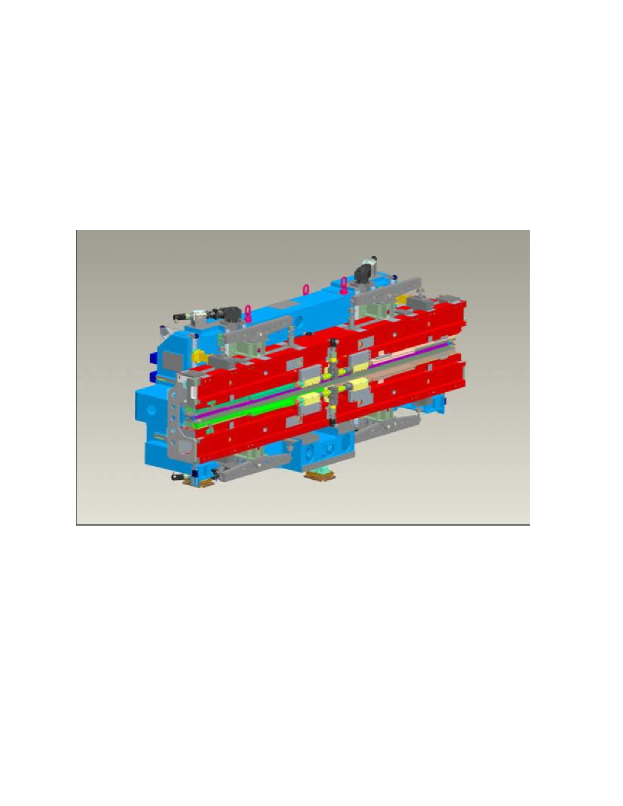
It has been proposed GENG that the radiation in the helical radiator can be tuned to the second harmonic (second harmonic afterburner helical radiator), and is therefore characterized by a different frequency compared to the linearly polarized radiation, tuned at the fundamental. However, for the LCLS this option can be extended only down to 1 keV and cannot cover the most interesting region between eV and eV. Another possible solution KUSK is based on the use of APPLE III type undulator modules. At the LCLS, saturation of the linearly polarized radiation at nm is reached after undulator modules, with a saturation power is about 10 GW. In order to reduce the linearly-polarized background, and to reach a degree of circular polarization larger than , APPLE III undulators need to be installed before the linearly polarized output reaches the GW power level, i.e. one needs to install three undulator modules. The main drawback of this scheme is constituted by the technical challenge of producing long helical insertion devices, since APPLE III type undulators have not yet come into operation. Finally, in OURC we proposed a third option which mainly consists of sending the electron beam, after the passage through the baseline undulator, through a m -long straight section, and subsequently through a short helical radiator. The background radiation from the baseline undulator is suppressed by letting radiation and electron beam through Beryllium vertical and horizontal slits upstream the helical radiator, where the radiation spot size is about ten times larger than the electron bunch transverse size. The option proposed in OURC has advantages in terms of cost and time, not only because helical undulator would be only m-long, but also because we can afford to use the existing design of APPLE II type undulators, Fig. 1, improved for PETRA III BAHR .
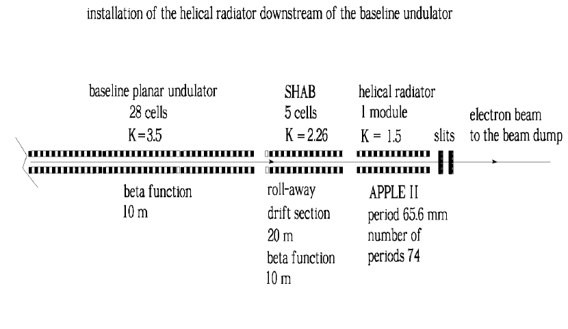
This paper proposes several modifications to improve the design presented in OURC . First, it seems reasonable that slits are placed immediately behind the helical radiator. The advantage of this choice over the previous one OURC is that the quality of the electron beam can now be spoiled by slits, since they are placed after helical radiator, and therefore a narrower width of the slits can be used for spatial filtering. In this way, the overall setup is fundamentally shorter than the previous one. Second, the helical radiator now is placed immediately behind the second harmonic afterburner (SHAB) undulator. We demonstrated by simulations performed with the code GENESIS GENE that in order to transport the microbunched electron beam through the m-ling straight section corresponding to the five SHAB undulator modules, it is sufficient to use, as a focusing lattice, the existing SHAB undulator FODO system with usual m betatron function function.
The new setup proposed in this work is extremely compact, and is composed of as few as two elements: the m-long APPLE II undulator module and the slits. The cost for a single APPLE II undulator module amounts to about million dollars, and manufacturing time can be estimated in two years. Altogether, in this paper we offer a new option for polarization control at the LCLS baseline which promises excellent cost-effective and risk-free results.
2 Circular polarization control scheme with spatial filtering out the linearly-polarized radiation behind the helical radiator.
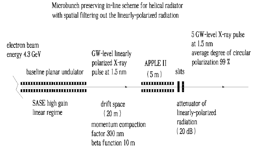
The principle upon which our scheme for polarization control is based is straightforward, and is illustrated in Fig. 2, Fig. 3 and Fig. 4. The electron beam first goes through the baseline undulator, it produces SASE radiation and is modulated in energy and density.
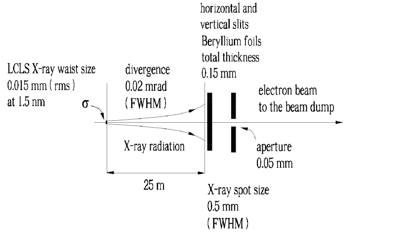
As in OURC , we assume here as well that the five second harmonic afterburner (SHAB) modules are rolled away BAIL from the beam line. In this way we provide a total m-long straight section for the electron beam transport, corresponding to the length of the SHAB modules. At the end of the straight section, that is immediately behind the SHAB undulator, we install a m-long APPLE II type undulator. While passing through this helical radiator, the microbunched electron beam produces intense bursts of radiation in any selected state of polarization. Subsequently, the polarized radiation from the APPLE II undulator, the linearly polarized radiation from the baseline undulator and the electron beam pass through horizontal and vertical slits. This results in a suppression of the linearly polarized radiation. In fact, since the slits are positioned m downstream of the planar undulator, the linearly-polarized radiation has about ten times larger spot size compared to the circularly-polarized radiation spot size, and the background radiation power can therefore be diminished of two orders of magnitude. The slits can be made out of Beryllium foils, for a total thickness of about mm. Such foils block the radiation, but lets the electrons go through.
In order to understand the effect of the foils on the electrons, we need to address multiple Coulomb scattering in the foils. We obtain a spoiled normalized emittance m. This normalized emittance is well within the acceptance of the beamline optics. The advantage of the spoiling scheme is that radiation is attenuated of dB, but the spoiled electron bunch is allowed to propagate through the straight line up to the beam dump without electron losses PREM .
The influence of the propagation of the electron beam through the drift section on the electron beam microbunching should be accounted for. One should account for the fact that straight section acts as a dispersive element with momentum compaction factor nm at an electron beam energy of GeV. The influence of the betatron motion should be further accounted for. In fact, the finite angular divergence of the electron beam, which is linked with the betatron function, leads to longitudinal velocity spread yielding microbunching suppression. In the next Section we present a comprehensive study of these effects. We simulated the evolution of the microbunching along the straight section, and we concluded that the transport of the microbunched electron beam through the m - long straight section does not constitute a serious problem for the realization of the proposed scheme.
3 FEL simulations
In this Section we report on a feasibility study performed with the help of the FEL code GENESIS 1.3 GENE running on a parallel machine. We will present a feasibility study for our method of polarization control at the LCLS, based on a statistical analysis consisting of runs. Parameters used in the simulations for the low-charge mode of operation are presented in Table 1. The choice of the low-charge mode of operation is motivated by simplicity.
| Units | ||
| Undulator period | mm | 30 |
| K parameter (rms) | - | 2.466 |
| Wavelength | nm | 1.5 |
| Energy | GeV | 4.3 |
| Charge | nC | 0.02 |
| Bunch length (rms) | m | 1 |
| Normalized emittance | mm mrad | 0.4 |
| Energy spread | MeV | 1.5 |
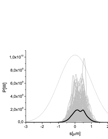
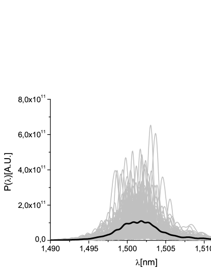
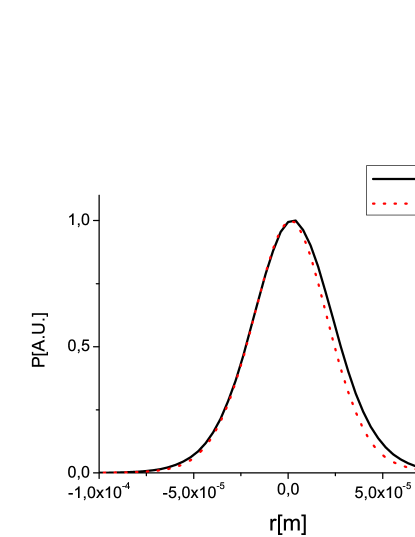
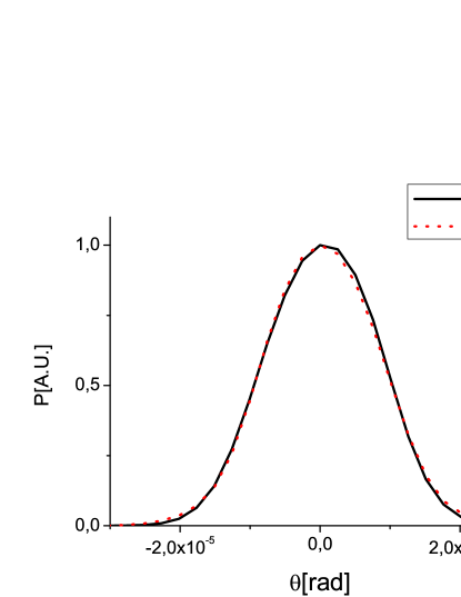

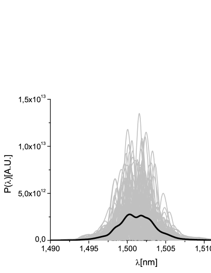
First, the baseline SASE undulator output was simulated. The result, in terms of power and spectrum, is shown in Fig. 5, while the angular distribution of the radiation is shown in Fig. 6. In order to obtain Fig. 6, we first calculated the intensity distribution along the bunch, so that in the left plot we present the energy density as a function of the transverse coordinates or , as if it was measured by an integrating photodetector. A two-dimensional Fourier transform of the data finally yields angular X-ray radiation pulse energy distribution. The and cuts are shown on the right plot.
The influence of quantum fluctuations in the baseline undulator was also studied. Only the five last cells were used, but one needs to account for the fact that beam passed, before the last five cells, through many detuned cells. Fig. 7 shows that such influence is negligible.
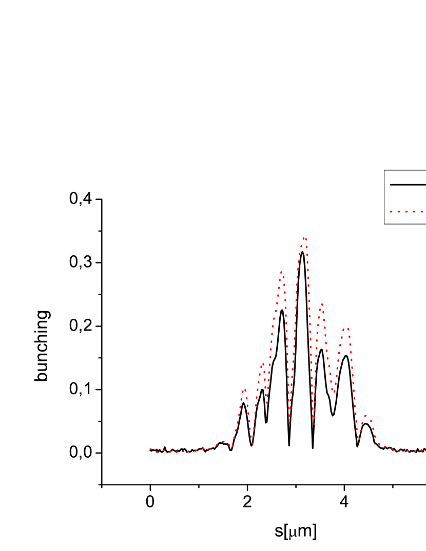

The GENESIS particle file was downloaded at the exit of the baseline undulator. For simulating the straight section in GENSIS, we used the same 5-cells undulator structure as for the baseline undulator, but we changed the undulator parameter to This choice allows one to have, with an accuracy of a fraction of percent, the same momentum compaction factor as in free space. Then the electron beam current was set to zero, and the undulator focusing was switched off (although for the undulator focusing effects are negligible). The GENESIS particle file was used as an input for the propagation of the bunch along the m-long FODO lattice. The average betatron function is assumed to be m. GENESIS automatically accounts for momentum compaction factor and betatron motion effects on the evolution of the microbunched beam. We tested the correctness of GENESIS simulations concerning the betatron motion effects in reference OUBE . The bunching before and after the straight section drift is shown in Fig. 9, upper plot, as a function of the longitudinal coordinate inside the electron bunch, for a particular run. The evolution of the middle slice bunching along the straight section for the same run is shown in Fig. 9, lower plot. Within the straight section, the bunching increases up to some maximum and then starts to decrease due to the longitudinal velocity spread originating from the beam energy spread and, additionally, from the betatron motion.
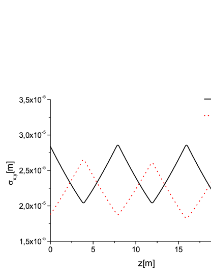
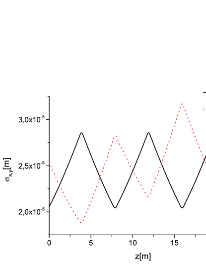
The evolution of the electron beam size in the horizontal and in the vertical direction inside the baseline undulator and in the straight section are shown in Fig. 8. Inspection of Fig. 8, right plot, shows a little mismatching in the vertical direction , which is not present in the left plot. This is due to the fact that in baseline undulator the electron beam was matched accounting for the undulator focusing properties. However, the mismatch was accounted for, because we used the particle file at the exit of straight section as input file for GENESIS simulations of the APPLE II output, meaning that the particle file was downloaded again at the end of the propagation through the straight section. Note that each cell begins with an undulator, and finishes with a quadrupole. Therefore we downloaded the particle file immediately after the first quadrupole related with propagation inside the APPLE II undulator. This guarantees correct propagation along the APPLE II undulator section, which is m long. The output files are downloaded immediately after the APPLE II undulator.
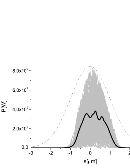
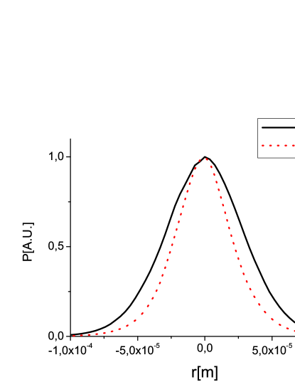
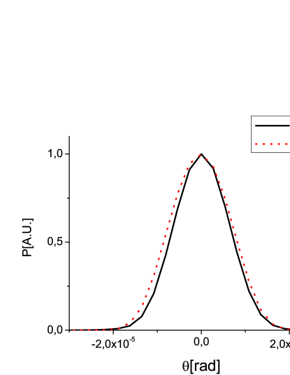
The final output from our setup is shown in Fig. 10, left plot, in terms of power and in Fig. 10, right plot, in terms of spectrum. In order to optimize the APPLE II output, the fifth section of the upstream planar undulator was detuned of by changing the undulator parameter from the number corresponding to exact resonance at nm at GeV. In this way a few-GW output power figure is granted, which is about the input level reported in Fig. 5. The transverse distribution of the radiation is shown in Fig. 11 in terms of transverse coordinates (left plot) and angles (right plot). From the analysis of Fig. 6 one finds an angular size of rad FWHM. As a result, after m propagation, the transverse size of the SASE radiation is about mm FWHM, to be compared with the APPLE II radiation spot size, which is just m. The SASE radiation spot size is, therefore, about ten times larger than the APPLE II radiation spot size. We assume, conservatively, the same energy level in both pulses. A slit system letting through the FWHM of the APPLE II radiation would let pass a relative contribution of linearized radiation of about , yielding a degree of circular polarization in excess of .
4 Conclusions
The LCLS baseline does not offer the possibility of polarization control. The output radiation is simply linearly polarized. Implementation of polarization control at LCLS baseline is a challenging problem, subject to many constraints including the request of a low cost, little available of time to implement setup changes, and guarantee of safe return to the baseline mode of operation. It is clear that the lowest-risk strategy for the implementation of polarization control at the LCLS baseline involves adding an APPLE II-type undulator at the end of the LCLS baseline undulator and exploiting the microbunching of the baseline planar undulator. Detailed experience is available in synchrotron radiation laboratories concerning the manufacturing of a m-long APPLE II undulator. However, the choice of short radiator leads to background suppression problems. In fact, the linearly-polarized radiation from the baseline undulator should be separated from the variably-polarized output from the APPLE II undulator. The driving idea of our proposal is that the background radiation can be suppressed by spatial filtering. This operation consists in letting radiation and electron beam through slits immediately behind the APPLE II undulator, which is placed immediately behind the whole ( cells) baseline undulator. The estimated cost is low enough to consider adding this scheme to the LCLS baseline in a two-years period.
5 Acknowledgements
We are grateful to Massimo Altarelli, Reinhard Brinkmann, Serguei Molodtsov and Edgar Weckert for their support and their interest during the compilation of this work.
References
- [1] P. Emma et al., Nature photonics doi:10.1038/nphoton.2010.176 (2010)
- [2] H.Geng, Y. Ding and Z. Huang, Nucl.Instr. and Meth. A 622 (2010) 276
- [3] B. Kuske and J. Bahrdt, FEL Conference Proceedings 2008 p.348, ”Tolerance studies for APPLE undulators in FEL facilities”
- [4] G. Geloni, V. Kocharyan and E. Saldin, ”Circular polarization control for the LCLS baseline in the soft x-ray regime”, DESY 10-252 (2010).
- [5] J. Bahrdt et al., EPAC Conference Proceedings 2008 p 2219, ”APPLE undulator for PETRA III”
- [6] S Reiche et al., Nucl. Instr. and Meth. A 429, 243 (1999).
- [7] J. Bailey et al., FEL Conference Proceedings 2008 p.460, ”Design and construction of the LCLS undulator system”
- [8] P.Emma, Phys. Rev. Letters 92 N7 (2004) 074801-1
- [9] G. Geloni, V. Kocharyan and E. Saldin, ”The effects of betatron motion on the preservation of FEL microbunching”, DESY 11-081 (2011).