Numerical study of secondary electron emission in a coaxial
radio-frequency driven plasma jet at atmospheric pressure
T. Hemke1, J. Trieschmann1, A. Wollny1,
R.P. Brinkmann1, T. Mussenbrock1
1 Theoretische Elektrotechnik, Ruhr-University Bochum, 44801 Bochum, Germany
In this work we investigate a numerical model of a coaxial RF-driven plasma jet operated at atmospheric pressure. Due to the cylindrical symmetry an adequate 2-D representation of the otherwise 3-dimensional structure is used. A helium-oxygen chemistry reaction scheme is applied. We study the effect of secondary electrons emitted at the inner electrode as well as the inserted dielectric tube and discuss their impact on the discharge behavior. We conclude that a proper choice of materials can improve the desired mode of operation of such plasma jets in terms of materials and surface processing.
1. Introduction
Microplasmas operated at atmospheric pressure have recently gained high attention [1].
A particularly popular class of microplasmas are non-equilibrium
radio-frequency driven plasma jets,
originally proposed by Selwyn and co-workers in 1998 [2].
Many groups have investigated their prospect for surface modification;
the studied processes include etching of tungsten, deposition and
etching of silicon oxide, and cleaning of thermolabile surfaces from contaminants.
In order to realize a jet concept for coating applications,
e.g. homogeneous thin film deposition from C2H2,
von Keudell and co-workers developed a micro-scaled axis-symmetric
radio-frequency driven plasma jet operated at atmospheric pressure [3].
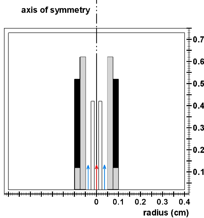
The schematics of their device is depicted in Fig. 1.
A stainless steel capillary is inserted into a ceramic tube leaving an annular
space of 0.25 mm between the outer radius of the capillary and the inner
radius of the ceramic tube.
The ceramic tube is finally surrounded by an aluminum tube.
This outer tube is now driven through a matching network by an
RF voltage at 13.56 MHz. In contrast the inner capillary
acts as the grounded counter electrode.
A feed gas (helium or argon) is guided in the capillary (red arrow) and the
annular space between the capillary and the ceramic tube (blue arrows),
while a small amount of a reactive gas is additionally injected through the capillary.
Besides proving the successful operation of this device as depositing tool
the coaxial jet is investigated experimentally by
means of phase resolved optical emission spectroscopy (PROES).
Four different modes of the discharge are distinguished in [4].
In this work we study the coaxial jet by means of a two-dimensional numerical
simulation. We take advantage of the axis-symmetric geometry and resolve
the radial and axial directions of the jet. In particular, we focus on the role
of the secondary electrons emitted at the ceramic tube and the
grounded capillary in order to characterize the -modes of the
discharge.
2. Simulation
2.1. Description of the numerical code
The simulations of this study are carried out with the fluid dynamics
code nonPDPSIM designed and realized by Kushner and co-workers.
For a detailed description of the code see publication [5]
and the citations therein. Here, we just briefly
discuss the implemented equations and the underlying physics.
The code nonPDPSIM simulates the dynamics of weakly ionized plasmas in the regime of medium to high pressure. It takes into account the physics and chemistry of charged particles – electrons with mass and charge , ions with mass and charge – and of the excited as well as the ground state neutrals (mass ). For all species , the continuity equations (particle balances) are simultaneously solved, where is the particle flux density and is the source and loss term, respectively:
| (1) |
The fluxes are calculated from the momentum balances in the drift-diffusion approximation evaluated in the local center-of-mass system. and are the diffusion constant and the mobility (if applicable) of species . Further, is the electrical field, and is the mass-averaged advective velocity of the medium:
| (2) |
For the electron fluid, additionally an energy balance equation is solved taking into account Ohmic heating and the energy losses due to elastic and inelastic interaction with the neutrals and ions as well as heat conduction,
| (3) | ||||
To capture the non-Maxwellian behavior of the electrons, all electronic transport coefficients (the mobility , the diffusion constant , and the thermal conductivity ) as well as the electronic rate coefficients in eqs. (1) and (2) are calculated by the local mean energy method: A zero-dimensional Boltzmann equation for the electron energy distribution and the transport and rate coefficients is solved for the locally applicable gas composition and various values of the electrical field. The tabulated data are then consulted in dependence of the fluid dynamically calculated electron temperature .
The plasma equations are coupled to a modified version of the compressible Navier-Stokes equations which are solved for the gas density , the mean velocity , and the gas temperature . The contributions to the energy equation from Joule heating include only ion contributions; the heat transfer from the electrons is included as a collisional change in the enthalpy. The scalar pressure is given by the ideal gas law.
Finally, the potential is calculated from Poisson’s equation. (The code works in the electrostatic approximation such that .) The charge density on its right hand side stems from the charged particles in the plasma domain and from the bound charges at the surfaces. The coefficient represents the permittivity of the medium:
| (4) |
The surface charges are governed by a separate balance equation, where is the conductivity of the solid materials and the subscript indicates evaluation on the surface:
| (5) |
The dynamical equations are complemented by an appropriate set of
boundary conditions. Electrically, the walls are either powered or
grounded. With respect to the particle flow, they are either solid,
or represent inlets or outlets: The flow is specified to a given
flux, while the outlet flow is adjusted to maintain the pressure.
Finally, it is worth mentioning that the actual implementation of
the equations poses some difficulties due to the vast differences
in the time scales of the dynamics of the plasma and the neutrals.
These difficulties are overcome by the methods of time-slicing
and subcycling.
2.2. Details of the simulation case
The described model is employed to simulate the coaxial jet described before.
Fig. 1 provides (besides the schematic sketch of the jet)
the simulation domain.
We scaled down the length of the original experimental jet configuration
in order to reduce the number of grid nodes but
preserved the original radial dimensions.
In our case, the capillary is 4.25 mm long, the grounded electrode is 5.25 mm
and the ceramic tube is 6.25 mm long, respectively.
The capillary has an inner and outer radius of 0.1 mm and 0.25 mm,
the inner radius of the ceramic tube is 0.5 mm.
The simulation resolves the two cylindrical coordinates R and z.
Due to the azimuthal symmetry of the simulation ”three-dimensional physics”, e.g. spot attachment of the discharge at a surface, can not be resolved.
The device is operated in a pure helium atmosphere at 105 Pa with helium as feed gas and oxygen as the reactive gas. The feed gas in the annular space between the capillary and the ceramic tube is injected with a flow rate of 3 slm, corresponding to a maximum advective velocity of 80 m/s. To avoid turbulences of the gas flow at the tip of the capillary the flow rate of the gas injected in the capillary is set to maintain a similar advective velocity: Helium with an admixture of 1 % oxygen as reactive gas is guided in the capillary with a flow rate of 170 sccm. The outlet is controlled to maintain a constant pressure.
We apply a helium-oxygen chemistry reaction scheme which is described in detail in [6].
To study the role and influence of the secondary electrons on both surfaces
– the grounded capillary and the ceramic tube – we vary the secondary electron emission (SEE)
coefficient . Additionally, we weight for each ion species
to account for the different probabilities of emission of secondary electrons depending
on the ion species hitting the surface.
3. Simulation results
We ignite the discharge numerically by seed electrons in the annular
space between the capillary and the ceramic tube.
The main ionization process during the numerical convergence
changes from volume to secondary electron dominated ionization.
This characteristic is found in the corresponding experiment
by increasing the applied voltage.
In the converged state the discharge runs in the -mode as
observed by the experiment.
Following, two distinct discharge regimes are discussed with simulation results. First, the SEE coefficient for the ceramic tube is set to , while in the second setting it is set to . The SEE coefficient for the capillary is in both cases. Apart from that all other simulation parameters are kept constant for both cases.
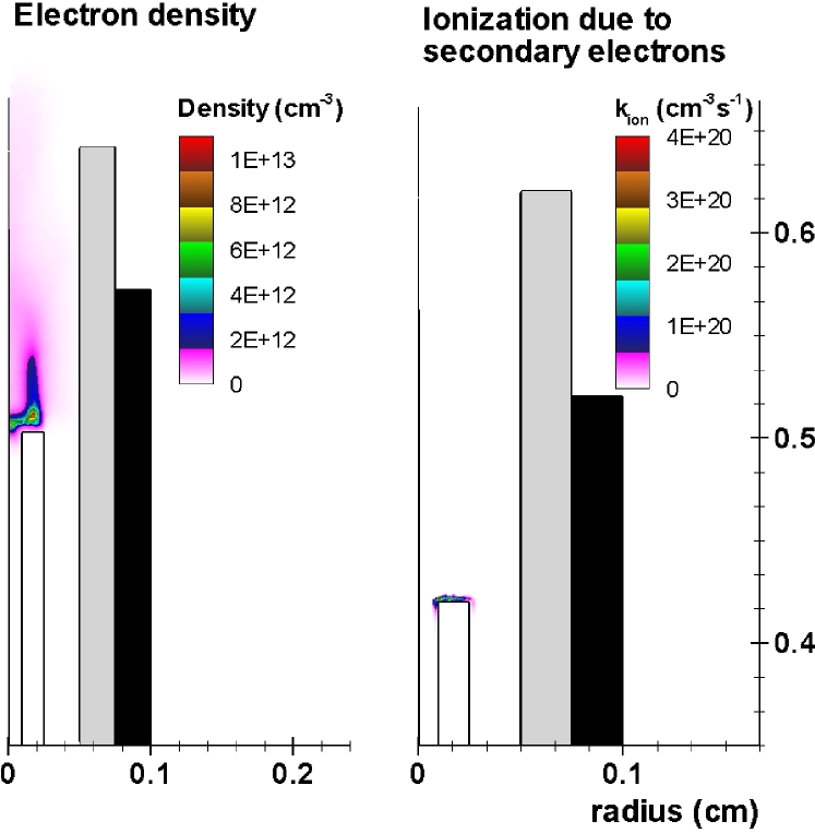
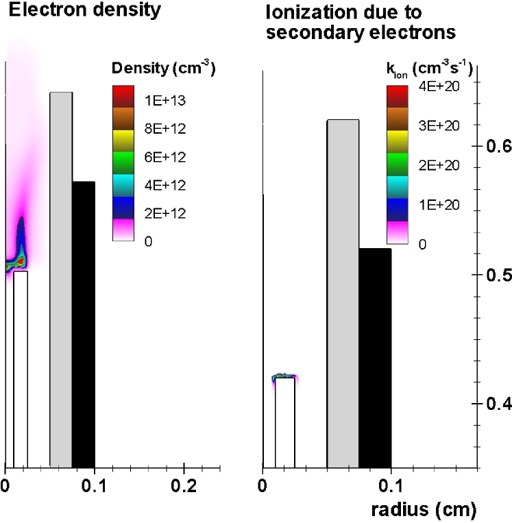
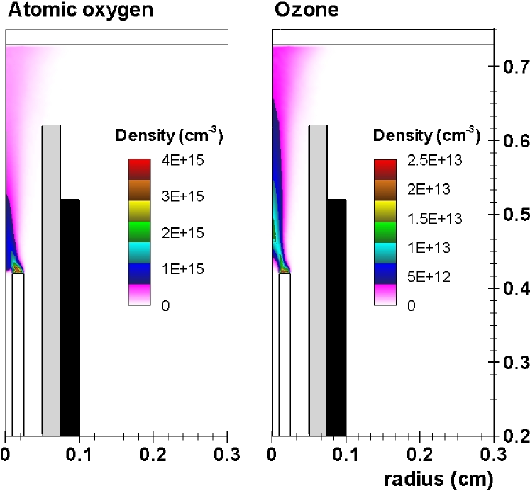
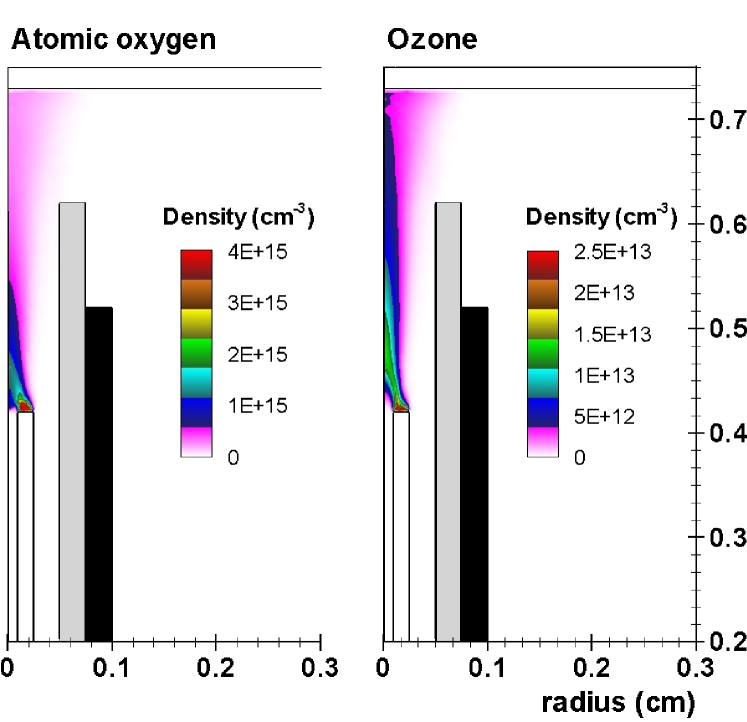
In order to investigate the influence of the secondary electrons emitted from the ceramic tube on the discharge, two aspects are characterized. As presented first in Figs. 2 and 3 the spatial profile of the electron density as well as the ionization due to secondary electrons is analyzed. This comparison is then followed by a comparison (compare Figs. 4 and 5) of the dominating chemically active species, namely atomic oxygen and ozone.
In both scenarios the influence of the SEE at the ceramic tube is clearly evident. E.g., when comparing the electron density distributions a shift towards the ceramic tube is clearly visible with SEE at the ceramic tube. This strongly indicates that these emitted electrons do play a significant role in the spatial distribution of the plasma discharge, bending it towards the surrounding ceramic tube.
With respect to reactive species the secondary electrons emitted from the ceramic tube again play an important role. As can be seen in the spatial profile of ozone (compare Fig. 5), which expands significantly further into the effluent of the plasma jet.
These results suggest that the SEE from materials adjacent to the plasma
in a coaxial setup has a significant influence on the spatial
profile of the plasma discharge. In particular a proper choice of these
materials can alter the discharge behavior with respect to the reactive
species which finally determine the applicability in terms of materials
and surface processing.
4. Conclusions
In this work we investigate a numerical model of a plasma
jet in coaxial configuration operated at atmospheric pressure.
We show that the emission of secondary electrons at the ceramic
tube adjacent to the plasma discharge has substantial
impact on the spatial distribution of the plasma as well as the
reactive species, e.g. ozone. Further we conclude that a proper
choice of materials can improve the desired mode of operation of
such plasma jets in terms of materials and surface processing.
5. Acknowledgment
The authors gratefully acknowledge fruitful discussions with
Prof. M.J. Kushner and Dr. N.Y. Babaeva from the University of
Michigan at Ann Arbor. Financial support by the Deutsche
Forschungsgemeinschaft in the frame of Research Group 1123
Physics of Microplasmas is also acknowledged.
References
References
- [1] K.H. Becker, H. Kersten, J. Hopwood, J.L. Lopez, Eur. Phys. J. D 60 (2010) 437439
- [2] S.E. Babayan, J.Y. Jeong, V.J. Tu, J.Park, G.S. Selwyn, R.F. Hicks, Plasma Sources Sci. Technol. 7 (1998) 286
- [3] J. Benedikt, K. Focke, A. Yanguas-Gil, A. von Keudell, Appl. Phys. Lett. 92 (2006) 251504
- [4] J. Benedikt, S. Hofmann, N. Knake, H. Böttner, R. Reuter, A. von Keudell, V. Schulz-von der Gathen, Eur. Phys. J. D 60 (2010) 539
- [5] N.Y. Babaeva, R.A. Arakoni, M.J. Kushner, J. Appl. Phys. 101 (2007) 123306
- [6] N.Y. Babaeva, M.J. Kushner, J. Appl. Phys. 101 (2007) 113307