Nonlinear response of microwave-irradiated two-dimensional electron systems near the second harmonic of the cyclotron resonance
Abstract
Recent experiments on microwave-irradiated high-mobility two-dimensional electron systems [Dai et al., Phys. Rev. Lett. 105, 246802 (2010), Hatke et al., Phys. Rev B 83 121301(R) (2011)] revealed a novel photoresistivity peak in the vicinity of the second cyclotron resonance harmonic. Here we report on the nonlinear transport measurements and demonstrate that the peak can be induced by modest dc fields and that its position is not affected even by strong dc fields, in contrast to microwave-induced resistance oscillations that shift to higher magnetic fields. These findings reinforce the notion that the peak cannot be described by existing models and provides important constraints for further theoretical considerations.
pacs:
73.40.-c, 73.21.-b, 73.43.-fOver the past decade, the regime of high Landau levels of high-mobility two-dimensional electron systems (2DESs) revealed a variety of remarkable transport phenomena. Some prominent examples include microwave-induced resistance oscillations (MIROs),(mir, a, ) phonon-induced resistance oscillations,(pir, ) Hall field-induced resistance oscillations,(hir, ) and several classes of combined oscillations.(com, a, b; Khodas and Vavilov, 2008) In addition, very clean microwave- and dc-driven 2DESs can exhibit zero-resistance states(zrs, a) and zero-differential resistance states,(zdr, ) respectively. These exotic states are believed to originate from instabilities of the 2DES with respect to formation of current domains.(zrs, b)
Mainstream theories of magnetoresistance oscillations are based on quantum kinetics and consider the displacement mechanism,(mir, b, b) originating from the modification of impurity scattering by microwave(mir, b) or dc(mir, b) electric fields, and the inelastic mechanism,(mir, b, b) stepping from the non-equilibrium energy distribution. Both mechanisms can give rise to MIROs which appear in photoresistivity , where is the dimensionless parameter proportional to the microwave power, , is the microwave frequency, is the cyclotron frequency, is the magnetic field, and is the electron effective mass. Hall field-induced resistance oscillations originate from the oscillatory correction to the differential resistivity due to the displacement mechanism,(mir, b) , where , is the cyclotron diameter, is the Fermi velocity, is the Hall electric field, is the Hall resistivity, is the direct current, and is the sample width. Under simultaneous application of dc and microwave fields, the resulting oscillations (com, a) in differential resistivity are governed by the displacement mechanism and can be described by(Khodas and Vavilov, 2008)
| (1) |
Here, is the Drude resistivity, is the Dingle factor, and , , and are the quantum, transport, and backscattering lifetimes, respectively. Equation (LABEL:acdc) well describes recent experiments(com, a) showing that the maxima occur along the lines defined by . This simple relation corresponds to the maximum value of the first term in the sum of Eq. (LABEL:acdc) which dominates the response under typical experimental conditions. In this scenario, the probability of inter-Landau level transitions due to microwave absorption and backscattering off of an impurity in the direction parallel to the dc field is maximized. The functional form of microwave- and Hall field-induced resistance oscillations can be obtained from Eq. (LABEL:acdc) by taking the limits and , respectively.
Very recently, experiments in irradiated high mobility 2DESs revealed yet another dramatic effect a distinct photoresistivity peak emerging near the second harmonic of the cyclotron resonance.(Dai et al., 2010; Hatke et al., 2011) In contrast to MIROs, which are known to decay with increasing microwave frequency, this so-called peak appears only above a certain frequency, which is about GHz in our 2DES. At higher frequencies, the peak can be more than an order of magnitude stronger than MIROs.(Hatke et al., 2011) This remarkable phenomenon cannot be explained by existing theories (mir, b, b) and its origin remains a mystery.
In this paper, we report on our experimental studies of the nonlinear response of this novel photoresistivity peak in a high-mobility 2DES. Our measurements are performed at a microwave frequency GHz which is somewhat lower than the critical frequency necessary for the observation of the peak at zero dc fields. Remarkably, the peak appears in nonlinear differential resistivity under a modest dc field, which apparently helps to separate it from MIROs. Once appeared, the peak persists over a wide range of dc fields but eventually weakens. Most importantly, we find that the position of the peak is largely insensitive to the applied dc field over the whole range of dc fields studied. This finding is in vast contrast to MIROs that shift substantially to higher magnetic fields as prescribed by Eq. (LABEL:acdc). These results strengthen the conclusion that the peak cannot be described by existing theories of microwave photoconductivity and provide important constraints for future theories.
Our sample is a Hall bar ( m) fabricated from a symmetrically doped GaAs/Al0.24Ga0.76As quantum well grown by molecular beam epitaxy. The density and the mobility were cm-2 and cm2/Vs. Microwave radiation was provided by Gunn oscillators feeding frequency doublers. Measurements were performed in a 3He cryostat at a constant coolant temperature K under continuous microwave irradiation in sweeping magnetic fields. Differential resistivity was measured over a wide range of , from 0 to 100 A, using a standard low frequency lock-in technique.
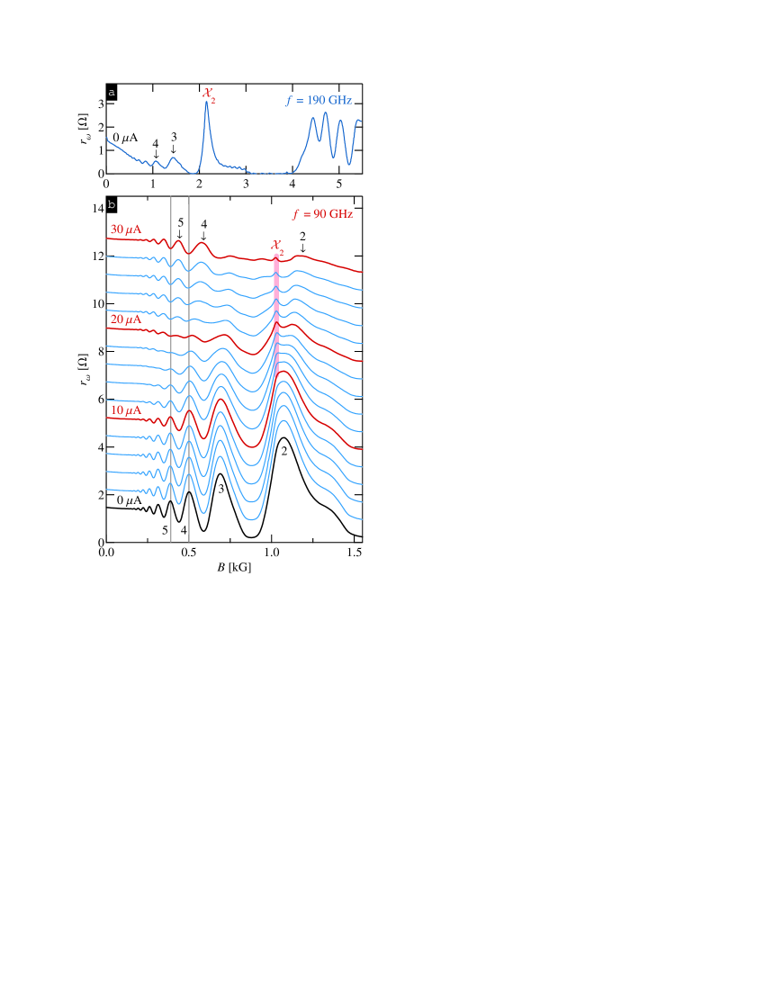
Before presenting our nonlinear transport data, we first present in Fig. 1 (a) the magnetoresistivity measured at and under microwave irradiation of frequency GHz. At this high frequency, the data clearly show not only MIROs and associated zero-resistance states, but also a giant peak which is superimposed on the second MIRO maximum. As mentioned in the introduction, this peak is not observable in our 2DES at when the frequency is below GHz. However, as we show next, dc fields make the peak visible even at lower frequencies.
In Fig. 1 (b) we present the differential magnetoresistivity, for direct currents from to A (bottom to top, with steps of 2 A) measured under microwave irradiation of GHz. The traces are vertically offset for clarity, and thick lines correspond to a step of 10 A. At zero-bias (bottom trace, ) the data exhibit pronounced MIROs which persist up to . The second MIRO maximum, where one might expect to see the peak, does not stand out in any way [cf. Fig. 1 (a)]. However, with increasing current up to A the second MIRO maximum broadens and at higher currents develops a sharp feature (cf. thick line). This feature is very narrow and, as we show below, is located between the second MIRO peak and the second harmonic of the cyclotron resonance. Based on its shape and position, we attribute this feature to the peak(Dai et al., 2010; Hatke et al., 2011) which appears in our 2DES without a dc bias at higher microwave frequencies [cf. Fig. 1 (a)]. The very fact that a modest dc field can cause the appearance of the peak, separating it from MIROs, indicates that its nonlinear response is different from that of MIROs.
Further examination of the data in Fig. 1 (b) reveals that all MIRO maxima shift to higher with increasing current (cf. ). Because most of this shift occurs within a relatively narrow current range, where the oscillation amplitude is strongly suppressed, it can also be viewed as a development of a MIRO maximum into a minimum at a given . Indeed, the fourth and fifth MIRO maxima at both evolve into the minima at A (cf. thin vertical lines). This evolution with increasing is consistent with earlier experiments(com, a) and is well understood within the displacement model(Khodas and Vavilov, 2008) [cf. Eq. (LABEL:acdc)]. In light of such dramatic changes to the MIRO waveform, it is quite remarkable to see that the peak, once developed, does not change either its position or width in this range of currents (cf. thick line). As we show below, even higher dc fields do not alter the position of the peak.
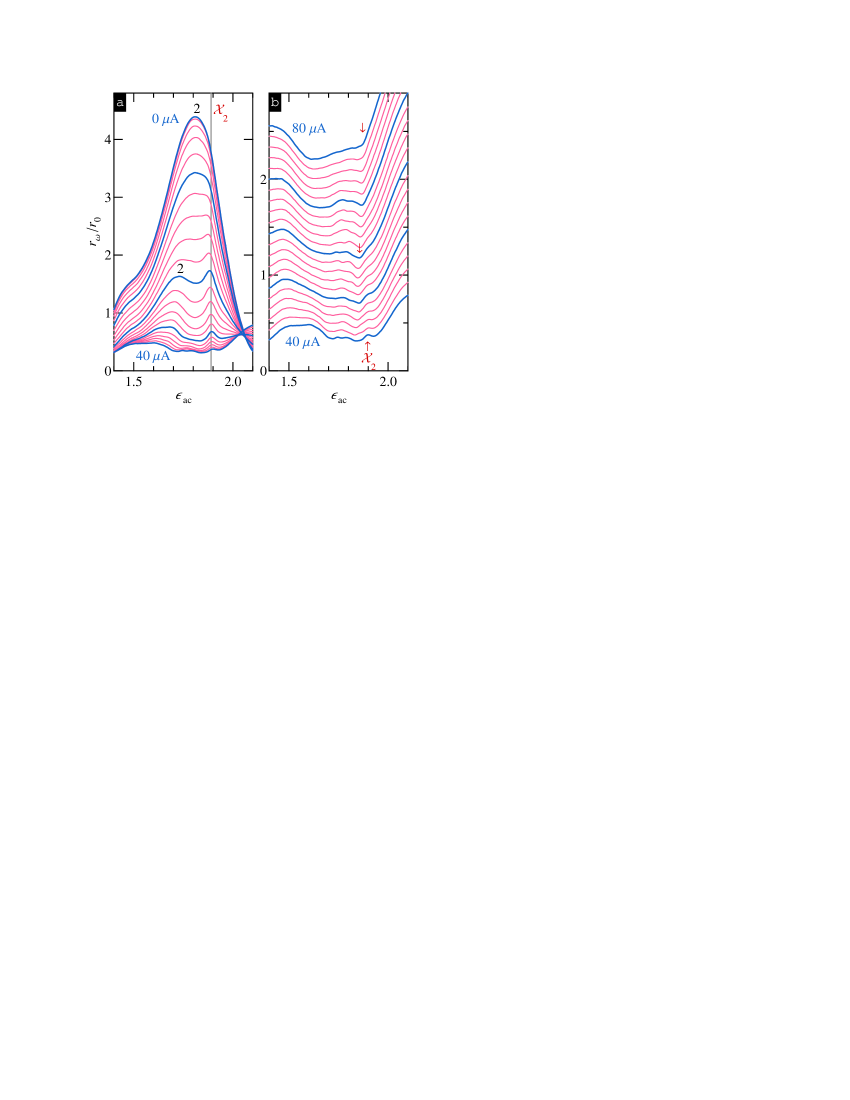
In Fig. 2 (a) we replot the differential resistivity, now normalized to its value at , , as a function of for direct currents from to A in steps of 2 A under microwave irradiation of GHz. Plotted in such a way, the data clearly demonstrate that the peak occurs at (cf. vertical line), which falls in between the second MIRO maximum and the second harmonic of the cyclotron resonance, . The data further show that in the range between 30 A and 40 A the magnitude of the peak is reduced considerably but its position remains unchanged.
In Fig. 2 (b) we present the results obtained at still higher currents, from A (bottom curve) to A (top curve) in steps of 2 A. The data are vertically offset for clarity by 0.1, and thick lines again correspond to a step of 10 A. While the peak continues to decay with increasing current, it remains clearly visible up to A. Concurrent with the decay of the peak, a rather sharp minimum develops at a slightly lower (cf. ). At higher currents, A, this minimum becomes the most pronounced feature in close vicinity to the original peak (cf. at the top trace). Based on the conversion of the MIRO maxima into the minima, as illustrated in Fig. 1 (b), one might consider a possibility that this minimum originates from the peak in a similar way but with a very different energy scale involved.
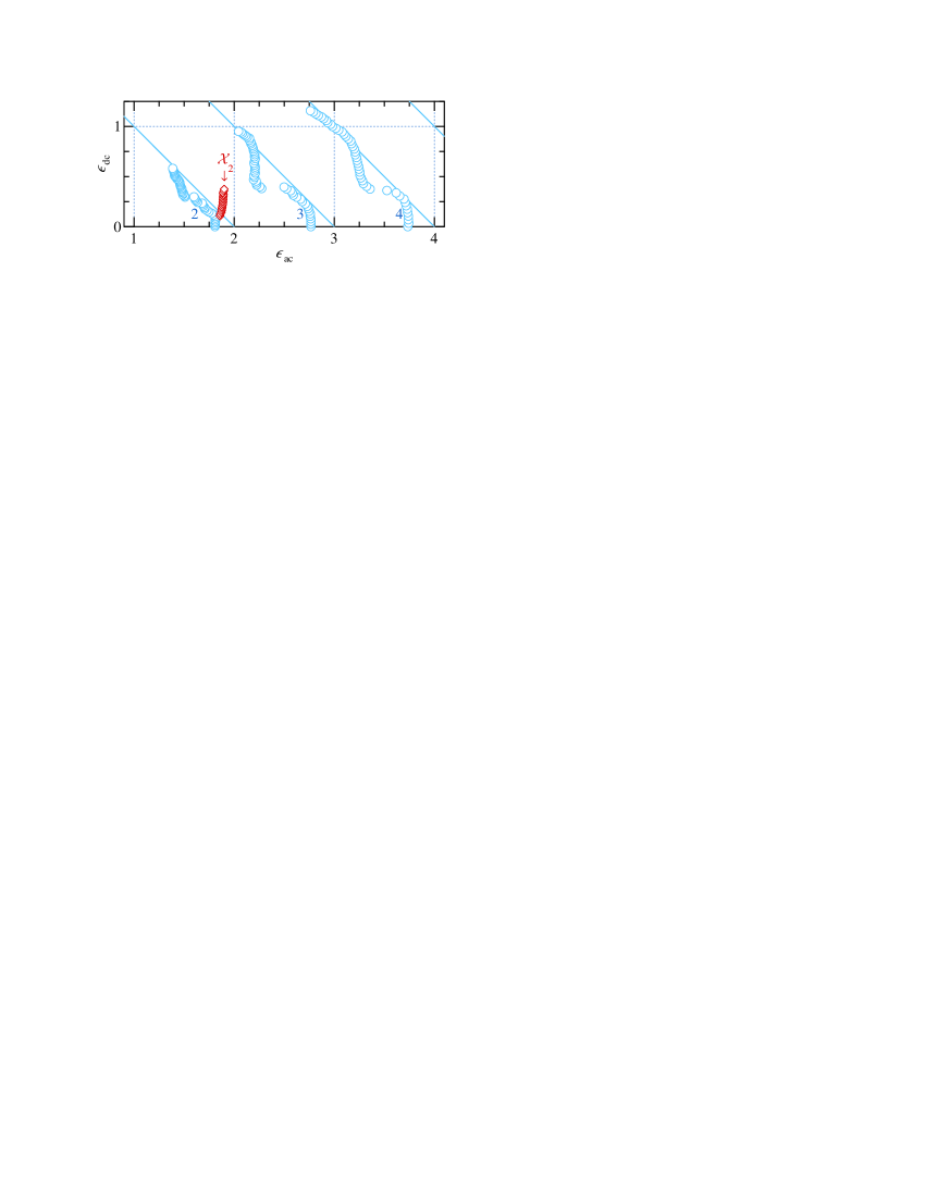
To summarize our observations, we now extract both and from our experimental data for the selected maxima obtained at direct currents up to 100 A. Figure 3 shows the results of this extraction on a () plane both for the MIRO maxima (cf. ) and for the peak (cf. ). At small , MIRO maxima appear(mir, ) at , where and . At somewhat higher dc fields, these maxima are well described by a linear dependence, (cf. solid lines), in agreement with Eq. (LABEL:acdc). At , roughly corresponding to the first minimum of Hall field-induced resistance oscillations, higher order () MIRO maxima quickly jump to , a position for the MIRO minima which remains satisfied for . This jump is a result of the maxima (minima) conversion into the minima (maxima) as seen in Fig. 1 (b). At still higher , maxima again follow linear dependence, .
In contrast to MIROs, the peak exhibits very different behavior. Once developed at , the peak is found at , where . At higher dc fields, the position of the peak remains essentially unchanged () over the whole range of currents over which the peak is observed. A closer examination of the data reveals that the peak, in fact, moves slightly towards the second harmonic of the cyclotron resonance, the direction which is opposite to that of MIROs. However, this move can be caused by a fast decay of the neighboring MIRO peak and by its fast movement towards lower with increasing dc field.
In summary, we have studied the nonlinear response of irradiated high-mobility 2DESs, focusing on the recently discovered(Dai et al., 2010; Hatke et al., 2011) photoresistivity peak, which appears in the vicinity to the second harmonic of the cyclotron resonance and high microwave frequencies. We have found that at microwave frequencies slightly below the minimum frequency necessary for the observation of this peak at zero dc field, the peak appears in nonlinear differential resistivity under a modest dc field, which apparently helps to separate it from MIROs. Once developed, the peak persists over a wide range of dc fields and eventually disappears. Most importantly, the position of this peak is not changed significantly over the whole range of dc fields. This behavior is in contrast to the evolution of microwave-induced resistance oscillations that shift to higher magnetic fields in accordance with the displacement model, as prescribed by Eq. (LABEL:acdc). Our findings further indicate that the nature of the peak is different from that of MIROs and provide important constraints for theoretical considerations.
We thank I. Dmitriev, M. Khodas, and B. Shklovskii for discussions, and S. Hannas, G. Jones, J. Krzystek, T. Murphy, E. Palm, J. Park, D. Smirnov, and A. Ozarowski for technical assistance. A portion of this work was performed at the National High Magnetic Field Laboratory, which is supported by NSF Cooperative Agreement No. DMR-0654118, by the State of Florida, and by the U.S. Department of Energy (DOE). The work at Minnesota was supported by the DOE Grant No. DE-SC0002567 (high frequency measurements at NHMFL) and by the NSF Grant No. DMR-0548014 (low frequency measurements at Minnesota). The work at Princeton was partially funded by the Gordon and Betty Moore Foundation as well as the NSF MRSEC Program through the Princeton Center for Complex Materials (DMR-0819860). A.T.H. acknowledges support from the University of Minnesota.
References
- mir (a) M. A. Zudov, R. R. Du, J. A. Simmons, and J. L. Reno, Phys. Rev. B 64, 201311(R) (2001); S. I. Dorozhkin, J. H. Smet, V. Umansky, and K. von Klitzing, ibid. 71, 201306(R) (2005); C. L. Yang, R. R. Du, L. N. Pfeiffer, and K. W. West, ibid. 74, 045315 (2006); O. M. Fedorych, M. Potemski, S. A. Studenikin, J. A. Gupta, Z. R. Wasilewski, and I. A. Dmitriev, ibid. 81, 201302 (2010); I. V. Andreev, V. M. Murav ev, I. V. Kukushkin, S. Schmult, and W. Dietsche, ibid. 83, 121308(R) (2011); P. D. Ye, L. W. Engel, D. C. Tsui, J. A. Simmons, J. R. Wendt, G. A. Vawter, and J. L. Reno, Appl. Phys. Lett. 79, 2193 (2001); A. T. Hatke, M. A. Zudov, L. N. Pfeiffer, and K. W. West, Phys. Rev. Lett. 102, 066804 (2009).
- (2) M. A. Zudov, Phys. Rev. B 69, 041304(R) (2004); S. A. Studenikin, M. Potemski, A. Sachrajda, M. Hilke, L. N. Pfeiffer, and K. W. West, ibid. 71, 245313 (2005); S. A. Studenikin et al., ibid. 76, 165321 (2007); R. R. Du, M. A. Zudov, C. L. Yang, L. N. Pfeiffer, and K. W. West, Phys. E (Amsterdam) 22, 7 (2004).
- (3) M. A. Zudov, I. V. Ponomarev, A. L. Efros, R. R. Du, J. A. Simmons, and J. L. Reno, Phys. Rev. Lett. 86, 3614 (2001); A. T. Hatke, M. A. Zudov, L. N. Pfeiffer, and K. W. West, ibid. 102, 086808 (2009); I. V. Ponomarev and A. L. Efros, Phys. Rev. B 63, 165305 (2001); X. L. Lei, ibid. 77, 205309 (2008); O. E. Raichev, ibid. 80, 075318 (2009).
- (4) C. L. Yang, J. Zhang, R. R. Du, J. A. Simmons, and J. L. Reno, Phys. Rev. Lett. 89, 076801 (2002); W. Zhang, H.-S. Chiang, M. A. Zudov, L. N. Pfeiffer, and K. W. West, Phys. Rev. B 75, 041304(R) (2007); J. Q. Zhang, S. Vitkalov, A. A. Bykov, A. K. Kalagin, and A. K. Bakarov, ibid. 75, 081305 (2007); A. T. Hatke, M. A. Zudov, L. N. Pfeiffer, and K. W. West, ibid. 79, 161308(R) (2009); 83, 081301(R) (2011); X. L. Lei, Appl. Phys. Lett. 90, 132119 (2007).
- com (a) W. Zhang, M. A. Zudov, L. N. Pfeiffer, and K. W. West, Phys. Rev. Lett. 98, 106804 (2007); Phys. E (Amsterdam) 40, 982 (2008); A. T. Hatke, H.-S. Chiang, M. A. Zudov, L. N. Pfeiffer, and K. W. West, Phys. Rev. Lett. 101, 246811 (2008); Phys. Rev. B 77, 201304(R) (2008); M. A. Zudov, H.-S. Chiang, A. T. Hatke, W. Zhang, L. N. Pfeiffer, and K. W. West, Int. J. of Mod. Phys. B 23, 2684 (2009).
- com (b) W. Zhang, M. A. Zudov, L. N. Pfeiffer, and K. W. West, Phys. Rev. Lett. 100, 036805 (2008); M. Khodas, H. -S. Chiang, A. T. Hatke, M. A. Zudov, M. G. Vavilov, L. N. Pfeiffer, and K. W. West, ibid. 104, 206801 (2010); X. L. Lei, Phys. Rev. B 79, 115308 (2009); I. A. Dmitriev, R. Gellmann, and M. G. Vavilov, ibid. 82, 201311 (2010).
- Khodas and Vavilov (2008) M. Khodas and M. G. Vavilov, Phys. Rev. B 78, 245319 (2008).
- zrs (a) R. G. Mani, J. H. Smet, K. von Klitzing, V. Narayanamurti, W. B. Johnson, and V. Umansky, Nature (London) 420, 646 (2002); M. A. Zudov, R. R. Du, L. N. Pfeiffer and K. W. West, Phys. Rev. Lett. 90, 046807 (2003); 96, 236804 (2006); Phys. Rev. B 73, 041303(R) (2006); R. R. Du, M. A. Zudov, C. L. Yang, Z. Q. Yuan, L. N. Pfeiffer, and K. W. West, Int. J. of Mod. Phys. B 18, 3465 (2004); C. L. Yang, M. A. Zudov, T. A. Knuuttila, R. R. Du, L. N. Pfeiffer, and K. W. West, Phys. Rev. Lett. 91, 096803 (2003); R. L. Willett, L. N. Pfeiffer and K. W. West, ibid. 93, 026804 (2004); J. H. Smet, B. Gorshunov, C. Jiang, L. Pfeiffer, K. West, V. Umansky, M. Dressel, R. Meisels, F. Kuchar, and K. von Klitzing ibid. 95, 116804 (2005).
- (9) A. A. Bykov, J.-Q. Zhang, S. Vitkalov, A. K. Kalagin, and A. K. Bakarov, Phys. Rev. Lett. 99, 116801 (2007); A. T. Hatke, H.-S. Chiang, M. A. Zudov, L. N. Pfeiffer, and K. W. West, Phys. Rev. B 82, 041304(R) (2010).
- zrs (b) A. V. Andreev, I. L. Aleiner and A. J. Millis, Phys. Rev. Lett. 91, 056803 (2003); A. Auerbach, I. Finkler, B. I. Halperin and A. Yacoby, ibid. 94, 196801 (2005); P. W. Anderson and W. F. Brinkman, e-print arXiv:cond-mat/0302129; I. G. Finkler and B. I. Halperin, Phys. Rev. B 79, 085315 (2009).
- mir (b) V. I. Ryzhii, Sov. Phys. Solid State 11, 2078 (1970); V. I. Ryzhii, R. A. Suris, and B. S. Shchamkhalova, Sov. Phys. Semicond. 20, 1299 (1986); A. C. Durst, S. Sachdev, N. Read, and S. M. Girvin, Phys. Rev. Lett. 91, 086803 (2003); J. Shi and X. C. Xie, ibid. 91, 086801 (2003); X. L. Lei and S. Y. Liu, ibid. 91, 226805 (2003); M. G. Vavilov and I. L. Aleiner, Phys. Rev. B 69, 035303 (2004).
- mir (b) M. G. Vavilov, I. L. Aleiner, and L. I. Glazman, Phys. Rev. B 76, 115331 (2007).
- mir (b) I. A. Dmitriev, A. D. Mirlin, and D. G. Polyakov, Phys. Rev. Lett. 91, 226802 (2003); 99, 206805 (2007); Phys. Rev. B 70, 165305 (2004); 75, 245320 (2007); I. A. Dmitriev, M. G. Vavilov, I. L. Aleiner, A. D. Mirlin, and D. G. Polyakov, ibid. 71, 115316 (2005); I. A. Dmitriev, M. Khodas, A. D. Mirlin, D. G. Polyakov, and M. G. Vavilov, ibid. 80, 165327 (2009).
- Dai et al. (2010) Y. Dai, R. R. Du, L. N. Pfeiffer, and K. W. West, Phys. Rev. Lett. 105, 246802 (2010).
- Hatke et al. (2011) A. T. Hatke, M. A. Zudov, L. N. Pfeiffer, and K. W. West, Phys. Rev. B 83, 121301(R) (2011).