Delta Doping of Ferromagnetism in Antiferromagnetic Manganite Superlattices
Abstract
We demonstrate that delta-doping can be used to create a dimensionally confined region of metallic ferromagnetism in an antiferromagnetic (AF) manganite host, without introducing any explicit disorder due to dopants or frustration of spins. Delta-doped carriers are inserted into a manganite superlattice (SL) by a digital-synthesis technique. Theoretical consideration of these additional carriers show that they cause a local enhancement of ferromagnetic (F) double-exchange with respect to AF superexchange, resulting in local canting of the AF spins. This leads to a highly modulated magnetization, as measured by polarized neutron reflectometry. The spatial modulation of the canting is related to the spreading of charge from the doped layer, and establishes a fundamental length scale for charge transfer, transformation of orbital occupancy and magnetic order in these manganites. Furthermore, we confirm the existence of the canted, AF state as was predicted by de Gennes [P.-G. de Gennes, Phys. Rev. 118 141 1960], but had remained elusive.
In semiconductors, delta-doping Dingle et al. (1978) has led to record high mobilities in two-dimensional electron gases, spawning a number of fundamental discoveries and many novel applications. In the complex oxides, similar doping strategies may in principle be used to create two-dimensional analogs of the many collective phases found in these materials Logvenov et al. (2009); Kozuka et al. (2009). In this work, using AF La1-xSrxMnO3 as the host material, we have devised a delta-doping strategy for locally tailoring the strength of the F double-exchange interactions relative to the AF superexchange, creating a quasi two-dimensional region of enhanced moment. We do this without introducing a random disorder potential due to dopants, or the frustration inherent to some AF/F interfaces. Our approach is unique to systems where double-exchange (DE) and superexchange (SE) interactions compete, and cannot be realized in conventional semiconductors or metals.
In the seminal work of de Gennes de Gennes (1960), it was recognized that when the insulating AF parent compound of a manganite is doped with carriers, competition between DE and SE causes the AF spins to cant, in proportion to the doping. In real materials, additional effects such as the Jahn-Teller (JT) interactions, on-site Coulomb repulsions (Mott-Hubbard effects) and orbital ordering instabilities, all favor localizing the carriers and compete with DE. As a result, the transition between an AF insulator such as LaMnO3 to a F metal such as La0.80Sr0.20MnO3 does not follow de Gennes’ phase diagram but rather takes place through a mixed-phase region for intermediate values of Kawano et al. (1996). A tendency toward phase separation is believed to be a fundamental property of the double-exchange manganites Khomskii (2010) and may thwart the appearance of a homogeneous, canted AF phase Dagotto (2002).
The situation is quite different if one starts with La1-xSrxMnO3 for , which is also AF. The Mn electrons can go into one of two partially filled bands made of degenerate and orbitals. For this degeneracy is removed by the formation of a highly anisotropic -type AF order (planes of F spins that are mutually AF), with the electrons mainly occupying the orbital states van den Brink and Khomskii (1999). The transport is nearly metallic in-plane due to DE. However, the out-of-plane resistivity is orders of magnitude higher since the states are unoccupied and SE dominates in this direction Kuwahara et al. (1999). Upon doping with electrons toward , the orbitals begin to be occupied, DE begins to act in the out-of-plane direction, and the material transforms into a 3-dimensional F metal. We show in this work that by delta-doping an AF manganite SL with electrons, we locally enhance the DE which cants the spins away from AF alignment, resulting in a highly modulated magnetization. Our theoretical investigation shows that a JT distortion is instrumental in stabilizing this canted spin structure lying in the midst of the crossover from a 2D antiferromagnet to a 3D ferromagnet near .
We synthesized cation-ordered analogs of La0.5Sr0.5MnO3 by alternating single unit cell layers of LaMnO3 (LMO) and SrMnO3 (SMO) with atomic layer precision onto SrTiO3 substrates using ozone-assisted molecular beam epitaxy. Neutron diffraction measurements on these (LaMnO/(SrMnO superlattices confirmed the -type AF phase, and magnetometry measurements using a superconducting quantum interference device (SQUID) showed a net F moment near zero at low field Santos et al. (2009). Here, we present delta-doped SLs with nominal compositions and 0.47. The SL was made by alternating unit cell layers of LaMnO3 and SrMnO3 and inserting an additional LaMnO3 layer for every four LaMnO3/SrMnO3 bilayers sup . This sequence was repeated 9 times (9 supercells), to form the superlattice [(SMO1/LMO1)x4,LMO1]x9. A La0.56Sr0.44MnO3 alloy film with a thickness of 81 uc was made for direct comparison. The SL was made by inserting an extra LaMnO3 layer after every 9 LaMnO3/SrMnO3 bilayers, repeated 4 times: [(SMO1/LMO1)x4,LMO1,(SMO1/LMO1)x5]x4. Structural characterization of the SLs is discussed elsewhere sup ; Santos et al. (2009). By periodically inserting the extra LaMnO3 unit cell layer, we have delta-doped the MnO2 planes in the vicinity of the inserted LaMnO3 unit cell with electrons. Our investigation of these SLs by neutron scattering techniques was aimed at determining the influence of these delta-doped charges on the -type spin structure.
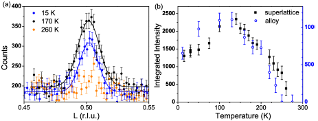
We performed neutron diffraction measurements to probe the spin structure in the SL and alloy. The -type order is manifested by a structurally-forbidden (0 0 ) Bragg peak, shown in Fig. 1a, signifying an AF spin alignment with a periodicity of normal to the film plane ( is the out-of-plane lattice parameter). From the full width at half-maximum of the peak, a magnetic coherence length of 28.5 nm was determined, nearly the entire film thickness (30.9 nm). The coexistence of both a (0 0 ) neutron diffraction peak and a net F moment from data sup suggests a canted AF structure, for which the spins within a single plane are ferromagnetically aligned and the spins on adjacent planes are canted at a relative angle , where is the angle between each spin and the applied magnetic field direction. The temperature dependence of the peak intensity in Fig. 1b indicates that the -type order in the SL disappears at 260 K.
To determine the depth-dependent magnetization profile, we performed polarized neutron reflectometry (PNR) measurements, which detect variations of in-plane magnetization as a function of sample depth along the surface normal. The non-spin-flip reflectivities, and shown in Fig. 2a for the SL, are sensitive to the component of magnetization parallel to the applied field direction. Because the nuclear scattering length densities of SMO and LMO are nearly identical, only magnetic variations in the layer profile are detectable. The key feature of interest here is the Bragg peak at Å-1, indicating that the magnetization is in fact modulated with a periodicity that matches the supercell periodicity of the SL.
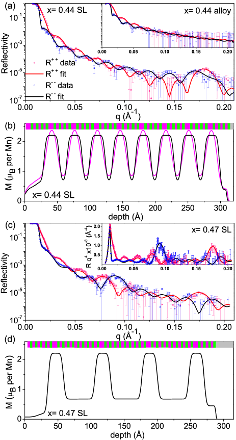
To fit the PNR data using the co_refine routine Fitzsimmons and Majkrzak (2005), a model consisting of 9 supercells was used, where each supercell consisted of a high moment sublayer and a low moment sublayer. The sublayer thicknesses, magnetic roughnesses and magnetic scattering length densities (a quantity directly proportional to the magnetization) of the seven interior supercells were fit while constrained to be identical, whereas the topmost and bottommost supercells could vary independently. For this data and model, there are several sets of possible fit parameters that yield the same lowest value to within 1%. Two such profiles are shown in Fig. 2b. Even though the highest (lowest) moment in the modulation period, () can each vary by as much as 0.25 , we can conclude with certainty across all sets of fit parameters that 1) the period of the magnetic modulation matches the structural supercell to within 0.1 nm; 2) the high moment sublayer contains the extra LMO layer and 3) the magnitude of the modulation is quite large, with .
The SL has a thicker supercell with one extra LMO layer for every 19 uc, such that two Bragg peaks are detectable, as shown in the PNR spectra in Fig. 2c. With this additional information on the magnetic modulation compared to the SL data set, the fitting routine produces a single set of best fit parameters at the lowest for the SL. A model similar to the one previously described, containing alternating high moment and low moment sublayers, was used to fit this data. The moment is again highly modulated, alternating between a high moment region across 6 uc (the full-width half-maximum of the peaks in Fig. 2d) containing the extra LMO unit cell and having , and a low moment region spanning 13 uc having . The gradual transition between and occurs over 4 uc, and as we shall show, this occurs by varying the canting angle. Using as the magnitude of the moment of a Mn3+/4+ spin and , the measured modulation of corresponds to a modulation of canting angle between and . These fit parameters also work for the SL, where the high moment region extends across 6 uc with , and the low moment region extends across 3 uc with , as shown in Fig. 2b (black line). In comparison, the PNR measurement of the alloy film (inset of Fig. 2a) shows a net moment without any modulation (no Bragg peak). Thus, the spin canting in the alloy is uniform, and the modulated magnetization in the and 0.47 SLs occurs due to the delta-doping.
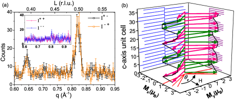
To investigate this canted spin structure further, we carried out diffraction measurements with polarized neutrons and polarization analysis in the vicinity of the AF peak for the SL, as shown in Fig. 3a. The peak in spin-flip intensities, and , at Å-1 results from the canted AF spins with each sublattice having a component of magnetization pointing perpendicular to the applied field direction, with a period of . Moreover, the superlattice peak at Å-1 signifies that the canted spin structure is modulated with a period of 9 uc, consistent with the supercell period and the periodicity of the F component revealed by the low PNR measurements not . These peaks in and directly confirm the canted, modulated spin structure. Fig. 3b shows the canted, modulated spin structure as deduced by the PNR and diffraction measurements.
In order to explore theoretically this canted spin state, we consider the standard two-orbital model for manganites Dagotto (2002) with the Hamiltonian sup . The double-exchange term , which arises from a combination of kinetic energy and strong Hund’s rule coupling, favors the F state. The superexchange term is the Heisenberg interaction between -spins favoring AF coupling. The Jahn-Teller term represents the coupling of the electrons to the lattice distortions.
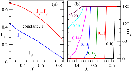
Before understanding the canted magnetic states, it is essential to understand the stability of -type AF order near in manganites. It is an outcome of a competition between the ferromagnetic and the antiferromagnetic terms, where denotes the relative angle between spins and , and the summation is over all nearest neighbors. -type order requires the F term to dominate in the -plane and the AF term to be stronger along the -axis. The presence of a uniform JT distortion favors the occupation of orbitals, which leads to a strong F interaction in the -plane and a much weaker one along the -axis, as seen in Fig. 4a (, where is the orbital occupancy and is the hopping integral in the direction). This leads to -type AF order for when the SE coupling . Upon reducing so that filling of the band continues, the doped electrons begin to fill the higher states (the states), so that increases and competes with while the in-plane order remains unaffected, as shown in Fig. 4a. Such a competition between F and AF interactions along the -axis can lead to canted spin states. From a simple energy minimization for , one finds that the canting angle if , and (F alignment) when . Note that within this scenario one needs to obtain (AF state). In reality there is a feedback effect of the spin states on the orbital occupancies that causes the variation of to be more abrupt. When the spins cant away from F alignment, this causes occupancy of the orbitals to decrease, which in turn causes to decrease further, making the spins cant even more. The cost in elastic energy in creating the lattice distortion with changes in orbital occupancy (-axis shrinks with lower ) prevents the transition from being a step function.
In order to test this explicitly, we minimize the total energy of the Hamiltonian for variational parameters and JT distortions, hence allowing for this feedback effect. At a fixed , JT distortions lead to a reduction in electronic energy but there is also an elastic cost associated with making these distortions sup . The optimum value of the distortion is selected from the above competition. This generates an dependence on the magnitude of the distortions and therefore an additional dependence on the values of . The resulting optimum angle is plotted in Fig. 4b for a few values of . The sharp change in from to for , 0.11 in the calculation does not allow for layers at intermediate with . This implies that it is not possible to stabilize a finite canting angle for these parameters. However, for and for , the variation in with is more gradual and layers with a finite canting angle are stable. Therefore, a small variation in the doping level can lead to significant changes in canting angle and thus the net F moment. The large modulation in moment as a function of depth in these delta-doped SLs is a realization of this scenario. Attempts to realize the canted AF state near as proposed by de Gennes and near have typically been obscured by phase segregation into F and AF domains Chmaissem et al. (2003), which is mitigated in our digital synthesis approach of charge doping without disorder. We note that a modulation in orbital occupancy is expected to accompany this modulated spin state Kiyama et al. (2003).
In conclusion, we have employed delta-doping to tailor the magnetic structure following the ideas of de Gennes. Localized regions of enhanced F exchange were created in an otherwise AF structure, where the transition between the high moment region and the low moment region occurs via a continuous variation of canting angle that is governed by the spreading of charge near the delta-doped layer. Furthermore, the PNR technique enables us to determine a length scale of 6 uc for the region of enhanced moment that is induced by the delta-doped layer. The result that the SL magnetization is highly modulated is evidence that the doped charges are not completely delocalized over the entire SL. Charge spreading out to 3 uc from both sides of the delta-doped layer is consistent with previous theoretical and experimental works that had inferred a length scale for charge spreading via more indirect means Lin et al. (2006); May et al. (2008). We believe this to signify a fundamental length scale for the spreading of charge normal to the layers.
Acknowledgements.
We are grateful to Chuck Majkrzak for helpful suggestions. Work at Argonne and use of the Center for Nanoscale Materials was supported by the U. S. Department of Energy, Office of Science, Office of Basic Energy Sciences, under Contract No. DE-AC02-06CH11357. A portion of this research at Oak Ridge National Laboratory’s High Flux Isotope Reactor was sponsored by the Scientific User Facilities Division, Office of Basic Energy Sciences, U.S. Department of Energy. We acknowledge the support of the National Institute of Standards and Technology, U.S. Department of Commerce, in providing the neutron research facilities used in this work. T.S. acknowledges support from the L’Oreal USA Fellowship for Women in Science.References
- Dingle et al. (1978) R. Dingle, H. Stormer, A. Gossard, and W. Wiegmann, Appl. Phys. Lett. 33, 665 (1978).
- Logvenov et al. (2009) G. Logvenov, A. Gozar, and I. Bozovic, Science 326, 699 (2009).
- Kozuka et al. (2009) Y. Kozuka, M. Kim, C. Bell, B. G. Kim, Y. Hikita, and H. Y. Hwang, Nature 462, 487 (2009).
- de Gennes (1960) P.-G. de Gennes, Phys. Rev. 118, 141 (1960).
- Kawano et al. (1996) H. Kawano, R. Kajimoto, M. Kubota, and H. Yoshizawa, Phys. Rev. B 53, R14709 (1996).
- Khomskii (2010) D. I. Khomskii, Basic Aspects of the Quantum Theory of Solids (Cambridge University Press, 2010).
- Dagotto (2002) E. Dagotto, Nanoscale Phase Separation and Colossal Magnetoresistance (Springer, 2002).
- van den Brink and Khomskii (1999) J. van den Brink and D. Khomskii, Phys. Rev. Lett. 82, 1016 (1999).
- Kuwahara et al. (1999) H. Kuwahara, T. Okuda, Y. Tomioka, A. Asamitsu, and Y. Tokura, Phys. Rev. Lett. 82, 4316 (1999).
- Santos et al. (2009) T. Santos, S. May, J. Robertson, and A. Bhattacharya, Phys. Rev. B 80, 155114 (2009).
- (11) See the Supplemental Material.
- Fitzsimmons and Majkrzak (2005) M. Fitzsimmons and C. Majkrzak, Modern Techniques for Characterizing Magnetic Materials (Springer, New York, 2005), chap. 3, pp. 107–155.
- (13) The SL periodicity (9) is found from the distance between the two peaks in Fig. 3a: ÅÅÅ.
- Chmaissem et al. (2003) O. Chmaissem, B. Dabrowski, S. Kolesnik, J. Mais, J. D. Jorgensen, and S. Short, Phys. Rev. B 67, 094431 (2003).
- Kiyama et al. (2003) T. Kiyama, Y. Wakabayashi, H. Nakao, H. Ohsumi, Y. Murakami, M. Izumi, M. Kawasaki, and Y. Tokura, J. Phys. Soc. J. 72, 785 (2003).
- Lin et al. (2006) C. Lin, S. Okamoto, and A. Millis, Phys. Rev. B 73, 041104(R) (2006).
- May et al. (2008) S. J. May, A. B. Shah, S. G. E. te Velthuis, M. R. Fitzsimmons, J. M. Zuo, X. Zhai, J. N. Eckstein, S. D. Bader, and A. Bhattacharya, Phys. Rev. B 77, 174409 (2008).