Brownian refrigeration by hybrid tunnel junctions

J. T. Peltonen Low Temperature Laboratory, Aalto University, P.O. Box 13500, FI-00076 AALTO, Finland    M. Helle Low Temperature Laboratory, Aalto University, P.O. Box 13500, FI-00076 AALTO, Finland Nokia Research Center, P.O. Box 407, FI-00045 NOKIA GROUP, Itämerenkatu 11-13, 00180 Helsinki, Finland    A. V. Timofeev Low Temperature Laboratory, Aalto University, P.O. Box 13500, FI-00076 AALTO, Finland VTT Technical Research Centre of Finland, P.O.Box 1000, FI-02044 VTT, Espoo, Finland    P. Solinas Department of Applied Physics/COMP, Aalto University, P.O. Box 14100, FI-00076 AALTO, Finland    F. W. J. Hekking Laboratoire de Physique et Modélisation des Milieux Condensés,
C.N.R.S. and Université Joseph Fourier, B.P. 166, 38042 Grenoble Cedex 9, France
   J. P. Pekola Low Temperature Laboratory, Aalto University, P.O. Box 13500, FI-00076 AALTO, Finland
Abstract

Voltage fluctuations generated in a hot resistor can cause extraction of heat from a colder normal metal electrode of a hybrid tunnel junction between a normal metal and a superconductor. We extend the analysis presented in [Phys. Rev. Lett. 98, 210604 (2007)] of this heat rectifying system, bearing resemblance to a Maxwell’s demon. Explicit analytic calculations show that the entropy of the total system is always increasing. We then consider a single electron transistor configuration with two hybrid junctions in series, and show how the cooling is influenced by charging effects. We analyze also the cooling effect from nonequilibrium fluctuations instead of thermal noise, focusing on the shot noise generated in another tunnel junction. We conclude by discussing limitations for an experimental observation of the effect.

pacs:
05.40.-a, 07.20.Pe, 73.40.Gk

I Introduction

Thermal ratchets and related devices invoke unidirectional flow of particles by a stochastic drive originating from fluctuations of a heat bath parrondo02 ; reimann02 ; buttiker87 ; astumian02 ; sokolov98 ; serreli07 ; hanggi09 ; sanchez11 . Analogously, thermal fluctuations can induce heat flow directed from cold to hot, which constitutes the principle of Brownian refrigeration. In recent literature, one can find two examples of a Brownian refrigerator broeck06 ; pekola07 . The first one broeck06 employs the idea of Feynman’s ratchet and pawl, and demonstrates that a Brownian refrigerator can work in principle, whereas the second refrigerator pekola07 relies on well-characterized properties of hybrid metallic tunnel junctions and presents thus an illustrative and concrete example of refrigeration by thermal noise.
Refer to caption
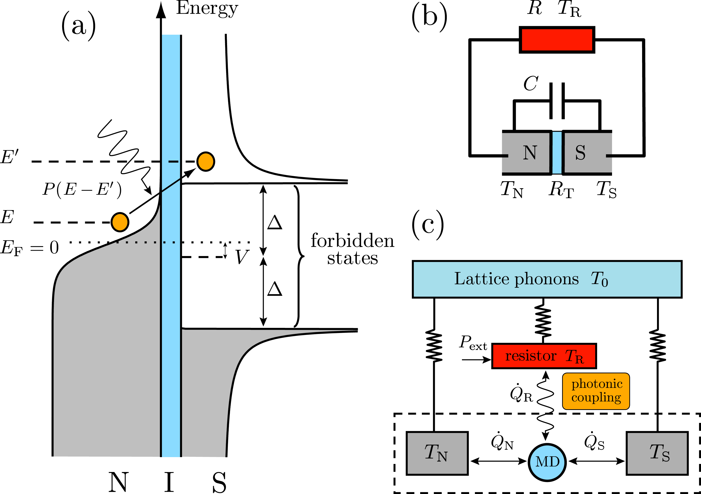
Figure 1: (color online) (a) Illustration of an environment-assisted tunneling event in an NIS junction. Voltage fluctuations generated by the electromagnetic environment of the junction provide the energy EEsuperscript𝐸𝐸E^{\prime}-E for the electron at E𝐸E to tunnel to available states at Esuperscript𝐸E^{\prime} on the superconductor side above the energy gap. For positive EEsuperscript𝐸𝐸E^{\prime}-E, P(EE)𝑃superscript𝐸𝐸P(E^{\prime}-E) is the probability density for the quasiparticle to emit energy EEsuperscript𝐸𝐸E^{\prime}-E to the environment, whereas P(EE)𝑃𝐸superscript𝐸P(E-E^{\prime}) describes the probability to absorb the energy EEsuperscript𝐸𝐸E^{\prime}-E. Removal of high energy electrons above the Fermi energy EFsubscript𝐸FE_{\mathrm{F}} (E0𝐸0E\geq 0, marked with the dotted line) results in refrigeration of the N island. V𝑉V denotes a constant DC bias voltage across the junction. For the Brownian refrigeration effect, V=0𝑉0V=0, and only a fluctuating voltage over the junction is present. (b) Electrical diagram of the resistor (resistance R𝑅R, temperature TRsubscript𝑇RT_{\mathrm{R}}) and the NIS junction (normal state tunnel resistance RTsubscript𝑅TR_{\mathrm{T}}, temperatures TNsubscript𝑇NT_{\mathrm{N}} and TSsubscript𝑇ST_{\mathrm{S}} for the normal metal N and superconductor S, respectively). The parallel capacitance C𝐶C includes the junction capacitance and a possible shunt capacitor. The N side of the junction can be connected to the resistor via a superconducting line with a direct NS contact. (c) Thermal diagram of the system. The NIS tunnel junction acts as Maxwell’s demon (MD), or as a Brownian refrigerator, between the normal metal island and the superconducting electrode. Q˙Nsubscript˙𝑄N\dot{Q}_{\mathrm{N}}, Q˙Ssubscript˙𝑄S\dot{Q}_{\mathrm{S}} and Q˙Rsubscript˙𝑄R\dot{Q}_{\mathrm{R}} denote heat flows in the system. Heat is carried by tunneling electrons in Q˙Nsubscript˙𝑄N\dot{Q}_{\mathrm{N}} and Q˙Ssubscript˙𝑄S\dot{Q}_{\mathrm{S}} whereas the resistor is coupled to the NIS junction only via voltage fluctuations, and the heat exchange can be described in terms of photonic coupling. Pextsubscript𝑃extP_{\mathrm{ext}} denotes the externally applied power needed to raise TRsubscript𝑇RT_{\mathrm{R}} over TNsubscript𝑇NT_{\mathrm{N}}. The electrons in the resistor, superconductor and the normal metal island are assumed to be thermally coupled to the lattice phonons, described as a heat bath at temperature T0subscript𝑇0T_{0}.

In Ref. pekola07, it was demonstrated that thermal noise generated by a hot resistor (resistance R𝑅R, temperature TRsubscript𝑇RT_{\mathrm{R}}) can, under proper conditions, extract heat from a cold normal metal (N) at temperature TNsubscript𝑇NT_{\mathrm{N}} in contact with a superconductor (S) at temperature TSsubscript𝑇ST_{\mathrm{S}} via environment-activated tunneling of electrons through a thin insulating barrier (I). At first sight, such an NIS junction seems to violate the second law of thermodynamics and act as Maxwell’s demon leff90 allowing only hot particles to tunnel out from the cold normal metal. This process would lead to a decrease of entropy if the system was isolated. Yet the demon needs to exchange energy with the surroundings in order to function properly. Thereby the net entropy of the whole system is always increasing. It is, however, interesting that one can exploit thermal fluctuations in refrigeration. In general, high frequency properties of the electrical environment close to small tunnel junctions have been known for a long time to be important in determining the particle tunneling rates and hence the current-voltage characteristic in such systems cleland90 ; delsing89 ; martinis89 ; holst94 . On the other hand, their influence on thermal transport has received less attention, motivating the study of heat currents in different electrical environments.

Cooling by electron tunneling is possible in a hybrid tunnel structure where one of the conductors facing the tunnel barrier has a hard gap in its quasiparticle density of states. An ordinary low temperature Bardeen-Cooper-Schrieffer (BCS) superconductor, such as aluminum, is an ideal choice for this. In principle, though not experimentally verified, a semiconductor with a suitable energy gap could also be a choice. The other conductor can be a superconductor with smaller energy gap manninen99 , a normal metal, or a heavily doped, metallic semiconductor savin01 . A hybrid NIS junction, or a contact of any type described above, can be characterized as a Maxwell demon under proper external conditions: the most energetic electrons are allowed to pass through the junction, whereas the low energy electrons are forbidden to tunnel. This feature makes the hybrid junctions unique, well characterized building blocks for energy filtering purposes.

Cooling of electrons in the N electrode is well understood in ordinary NIS junctions biased by a constant voltage giazotto06 , and it is utilized in practical electronic microrefrigerators nahum94 ; leivo96 . Recently, electronic cooling of a 2D electron gas has also been demonstrated prance09 , based on energy dependent tunneling through two quantum dots in series. In the case of an NIS junction subject to a noisy environment consisting of a hot resistor, the voltage fluctuations allow the most energetic electrons to tunnel from the cold normal metal, even under zero voltage bias across the junction. Figure 1 shows a schematic representation of the system. The phenomenon is analogous to photon assisted tunneling tien63 ; tucker85 with a stochastic source. The cooling is observed in a certain temperature range of the environment, TR>TNsubscript𝑇Rsubscript𝑇NT_{\mathrm{R}}>T_{\mathrm{N}}, where the distribution of thermal noise is suitable to excite hot electrons to tunnel through the NIS junction to the superconductor side. When the temperature TRsubscript𝑇RT_{\mathrm{R}} is further increased, the fluctuating voltage of the hot resistor starts to extract also cold electrons from the normal metal, resulting eventually in heating of the island. The heat flow is nontrivial also when the resistor is at a lower temperature than the normal metal (TN>TRsubscript𝑇Nsubscript𝑇RT_{\mathrm{N}}>T_{\mathrm{R}}): heat flows into the hot normal metal, and the superconductor side tends to cool down. Thus the reversal of the temperature bias reverses the heat fluxes. Such a reversed heat flow cannot be realized in a conventional voltage-biased NIS refrigerator, for instance by changing the polarity of the voltage bias giazotto06 .

The resistor and the junction can be connected by superconducting lines which efficiently suppress the normal electronic thermal conductance. Alternatively, the coupling can be capacitive instead of a direct galvanic connection, allowing to neglect the remaining quasiparticle thermal conductance timofeev09 . In both cases, the N electrode of the junction can be connected to the superconducting line via a direct metal-to-metal SN contact, which provides perfect electrical transmission but, due to Andreev reflection, exponentially suppresses heat flow at temperatures below the superconductor energy gap andreev64 ; giazotto06 . The size of the normal metal island is assumed to be small enough (small resistance compared to the tunnel resistance) to ignore the direct Joule heating by the voltage fluctuations. One should further keep in mind that in an on-chip realization, the two subsystems, i.e., the NIS junction and the resistor typically in the form of a thin strip of resistive metal such as chromium, are connected through substrate phonons. However, with a careful design and with low substrate temperature, unwanted heat flow via electron-phonon coupling from the resistor to the junction can be reduced to sufficiently low level in a practical realization of the device.

The text is organized as follows. In Sec. II we first expand the analysis presented in Ref. pekola07, of a single hybrid junction exposed to the noise of a hot resistor. In particular we give a transparent picture of the mechanism of Brownian refrigeration in this system and we make a systematic analysis in terms of different parameters affecting the cooling performance. In Sec. III we present quantitative considerations of entropy production in the system. We move on to Sec. IV to analyze a single electron transistor (SET) configuration, consisting of a double junction SINIS refrigerator subjected to thermal noise; here, charging effects of the small N island become relevant, and the heat currents can be controlled by a capacitively coupled gate electrode. In Sec. V we discuss briefly more general, non-ohmic dissipative environments. Section VI considers the refrigeration by nonequilibrium fluctuations, e.g., by shot noise generated in another voltage biased tunnel junction, instead of the thermal noise in an ohmic resistor. Finally, in Sec. VII we discuss practical aspects towards an experimental realization of the Brownian refrigeration device.

II A hybrid tunnel junction

The operation principle of the Brownian tunnel junction refrigerator is illustrated in Fig. 1 (a)a\left(\mathrm{a}\right), showing how an electron in the normal metal can absorb energy EEsuperscript𝐸𝐸E^{\prime}-E and tunnel into an available quasiparticle state above the energy gap ΔΔ\Delta in the superconductor. Figure 1 (b)b\left(\mathrm{b}\right) and (c)c\left(\mathrm{c}\right) display electric and thermal diagrams of the system, respectively. To calculate heat flows in the combined system of the NIS junction and the resistor, we utilize the standard P(E)𝑃𝐸P(E)-theory [for a review, see Ref. ingold92, ] describing a tunnel junction embedded in a general electromagnetic environment petheory . This circuit is characterized by a frequency-dependent impedance Z(ω)𝑍𝜔Z(\omega) at temperature TRsubscript𝑇RT_{\mathrm{R}} in parallel to the junction. To illustrate the effects of the environment, we mainly deal with the special case of a resistive environment with Z(ω)R𝑍𝜔𝑅Z(\omega)\equiv R frequency-independent in the relevant range. The theory is perturbative in the tunnel conductance, and we assume a normal state tunneling resistance RTRKmuch-greater-thansubscript𝑅Tsubscript𝑅KR_{\mathrm{T}}\gg R_{\mathrm{K}}, where RKh/e226kΩsubscript𝑅Ksuperscript𝑒2similar-to-or-equals26kΩR_{\mathrm{K}}\equiv h/e^{2}\simeq 26\;\mathrm{k}\Omega is the resistance quantum.

II.1 Heat fluxes for a single junction in a dissipative environment

We start by writing down the heat fluxes associated to quasiparticle tunneling in a general hybrid junction biased by a constant voltage V𝑉V, with normalized density of states (DoS) ni(E)subscript𝑛𝑖𝐸n_{i}(E) in each electrode (i=1,2𝑖12i=1,2). We assume that the two conductors are at (quasi) equilibrium, i.e., their energy distribution functions obey the Fermi-Dirac form fi(E)=1/[1+exp(βiE)]subscript𝑓𝑖𝐸1delimited-[]1subscript𝛽𝑖𝐸f_{i}(E)=1/[1+\exp(\beta_{i}E)] with the inverse temperature βi=(kBTi)1subscript𝛽𝑖superscriptsubscript𝑘Bsubscript𝑇𝑖1\beta_{i}=(k_{\mathrm{B}}T_{i})^{-1}. Here, importantly, the temperatures Tisubscript𝑇𝑖T_{i} need not be equal, and the energies are measured with respect to the Fermi level. In general the electrode temperatures are determined consistently by the various heat fluxes in the complete system, usually via coupling to the lattice phonons.

The net heat flux out of electrode i𝑖i is given by

Q˙i=subscript˙𝑄𝑖absent\displaystyle\dot{Q}_{i}= 1e2RTdEdEni(E)Efi(E)P(EE)×\displaystyle\frac{1}{e^{2}R_{\mathrm{T}}}\int_{-\infty}^{\infty}\int_{-\infty}^{\infty}dEdE^{\prime}n_{i}(E)Ef_{i}(E)P(E-E^{\prime})\times
{nj(E+eV)[1fj(E+eV)].\displaystyle\bigg{\{}n_{j}(E^{\prime}+eV)\left[1-f_{j}(E^{\prime}+eV)\right]\bigg{.}
.+nj(EeV)[1fj(EeV)]},\displaystyle\bigg{.}+n_{j}(E^{\prime}-eV)\left[1-f_{j}(E^{\prime}-eV)\right]\bigg{\}}, (1)

which assumes the symmetries ni(E)=ni(E)subscript𝑛𝑖𝐸subscript𝑛𝑖𝐸n_{i}(E)=n_{i}(-E) and fi(E)=1fi(E)subscript𝑓𝑖𝐸1subscript𝑓𝑖𝐸f_{i}(-E)=1-f_{i}(E). In case of Brownian refrigeration at V=0𝑉0V=0, the heat transport is only due to fluctuations in the environment. Equation (1) simplifies to pekola07

Q˙i=subscript˙𝑄𝑖absent\displaystyle\dot{Q}_{i}= 2e2RTdEdEn1(E)n2(E)Ei×\displaystyle\frac{2}{e^{2}R_{\mathrm{T}}}\int_{-\infty}^{\infty}\int_{-\infty}^{\infty}dEdE^{\prime}n_{1}(E)n_{2}(E^{\prime})E_{i}\times
f1(E)[1f2(E)]P(EE)subscript𝑓1𝐸delimited-[]1subscript𝑓2superscript𝐸𝑃𝐸superscript𝐸\displaystyle f_{1}(E)\left[1-f_{2}(E^{\prime})\right]P(E-E^{\prime}) (2)

with E1=Esubscript𝐸1𝐸E_{1}=E and E2=Esubscript𝐸2superscript𝐸E_{2}=-E^{\prime}, giving the heat extracted from electrode i𝑖i. On the other hand, Ei=EEsubscript𝐸𝑖superscript𝐸𝐸E_{i}=E^{\prime}-E for heat extracted from the environment, manifesting the conservation of energy. The function P(E)𝑃𝐸P(E) is obtained as the Fourier transform

P(E)=12π𝑑texp[J(t)+iEt/],𝑃𝐸12𝜋Planck-constant-over-2-pisuperscriptsubscriptdifferential-d𝑡𝐽𝑡𝑖𝐸𝑡Planck-constant-over-2-piP(E)=\frac{1}{2\pi\hbar}\int_{-\infty}^{\infty}dt\exp\left[J(t)+iEt/\hbar\right], (3)

with the phase-phase correlation function J(t)𝐽𝑡J(t) defined as

J(t)=𝐽𝑡absent\displaystyle J(t)= φ(t)φ(0)φ(0)φ(0)delimited-⟨⟩𝜑𝑡𝜑0delimited-⟨⟩𝜑0𝜑0\displaystyle\langle\varphi(t)\varphi(0)\rangle-\langle\varphi(0)\varphi(0)\rangle
=\displaystyle= 12π𝑑ωSφ(ω)[eiωt1].12𝜋superscriptsubscriptdifferential-d𝜔subscript𝑆𝜑𝜔delimited-[]superscript𝑒𝑖𝜔𝑡1\displaystyle\frac{1}{2\pi}\int_{-\infty}^{\infty}d\omega S_{\varphi}(\omega)\left[e^{-i\omega t}-1\right]. (4)

Here, Sφ(ω)subscript𝑆𝜑𝜔S_{\varphi}(\omega) is the spectral density of the phase fluctuations φ(t)𝜑𝑡\varphi(t) across the junction, i.e., the average value of φ(t)𝜑𝑡\varphi(t) satisfies φ(t)=0delimited-⟨⟩𝜑𝑡0\langle\varphi(t)\rangle=0. For a given Z(ω)𝑍𝜔Z(\omega) and a temperature kBTR=βR1subscript𝑘Bsubscript𝑇Rsuperscriptsubscript𝛽R1k_{\mathrm{B}}T_{\mathrm{R}}=\beta_{\mathrm{R}}^{-1} of the environment, the uniquely defined P(E)𝑃𝐸P(E) can be interpreted as the probability density per unit energy for the tunneling particle to exchange energy E𝐸E with the environment ingold92 , with E>0𝐸0E>0 corresponding to emission and E<0𝐸0E<0 to absorption. The function J(t)𝐽𝑡J(t) in Eq. (4) can then be written as

J(t)=𝐽𝑡absent\displaystyle J(t)= 20dωωRe[Zt(ω)]RK×\displaystyle 2\int_{0}^{\infty}\frac{d\omega}{\omega}\frac{\mathrm{Re}\left[Z_{\mathrm{t}}(\omega)\right]}{R_{\mathrm{K}}}\times
{coth(βRω/2)[cos(ωt)1]isin(ωt)}.hyperbolic-cotangentsubscript𝛽RPlanck-constant-over-2-pi𝜔2delimited-[]𝜔𝑡1𝑖𝜔𝑡\displaystyle\{\coth(\beta_{\mathrm{R}}\hbar\omega/2)[\cos(\omega t)-1]-i\sin(\omega t)\}. (5)

Here, Zt(ω)=1/[iωC+Z1(ω)]subscript𝑍t𝜔1delimited-[]𝑖𝜔𝐶superscript𝑍1𝜔Z_{\mathrm{t}}(\omega)=1/[i\omega C+Z^{-1}(\omega)], is the total impedance as seen from the tunnel junction, i.e., a parallel combination of the “external” impedance Z(ω)𝑍𝜔Z(\omega) and the junction capacitance C𝐶C. Inserting J(t)𝐽𝑡J(t) from Eq. (5) into Eq. (3), one importantly finds that P(E)𝑃𝐸P(E) is 1) positive for all E𝐸E, 2) normalized to unity, and 3) satisfies detailed balance P(E)=exp(βRE)P(E)𝑃𝐸subscript𝛽R𝐸𝑃𝐸P(-E)=\exp(-\beta_{\mathrm{R}}E)P(E). To relate P(E)𝑃𝐸P(E) and J(t)𝐽𝑡J(t) to more physical quantities, we use the fundamental defining relation between the phase φ(t)𝜑𝑡\varphi(t) and the voltage fluctuation δV(t)𝛿𝑉𝑡\delta V(t) across the junction. We have φ(t)=(e/)t𝑑tδV(t)𝜑𝑡𝑒Planck-constant-over-2-pisuperscriptsubscript𝑡differential-dsuperscript𝑡𝛿𝑉superscript𝑡\varphi(t)=(e/\hbar)\int_{-\infty}^{t}dt^{\prime}\delta V(t^{\prime}), from which it follows that Sφ(ω)subscript𝑆𝜑𝜔S_{\varphi}(\omega) is connected to the voltage noise spectral density SV(ω)subscript𝑆𝑉𝜔S_{V}(\omega) at the junction via Sφ(ω)=(e/)2SV(ω)/ω2subscript𝑆𝜑𝜔superscript𝑒Planck-constant-over-2-pi2subscript𝑆𝑉𝜔superscript𝜔2S_{\varphi}(\omega)=(e/\hbar)^{2}S_{V}(\omega)/\omega^{2}. Furthermore, P(E)𝑃𝐸P(E) is well approximated in the limit πR/RKβRECmuch-greater-than𝜋𝑅subscript𝑅Ksubscript𝛽Rsubscript𝐸C\pi R/R_{\mathrm{K}}\gg\beta_{\mathrm{R}}E_{\mathrm{C}} by a Gaussian of width s=2ECkBTR𝑠2subscript𝐸Csubscript𝑘Bsubscript𝑇Rs=\sqrt{2E_{\mathrm{C}}k_{\mathrm{B}}T_{\mathrm{R}}} centered at ECe2/(2C)subscript𝐸Csuperscript𝑒22𝐶E_{\mathrm{C}}\equiv e^{2}/(2C), the elementary charging energy of the junction ingold92 . Lowering R𝑅R transforms P(E)𝑃𝐸P(E) towards a delta-function at E=0𝐸0E=0.

II.2 Results for an NIS junction

Refer to caption
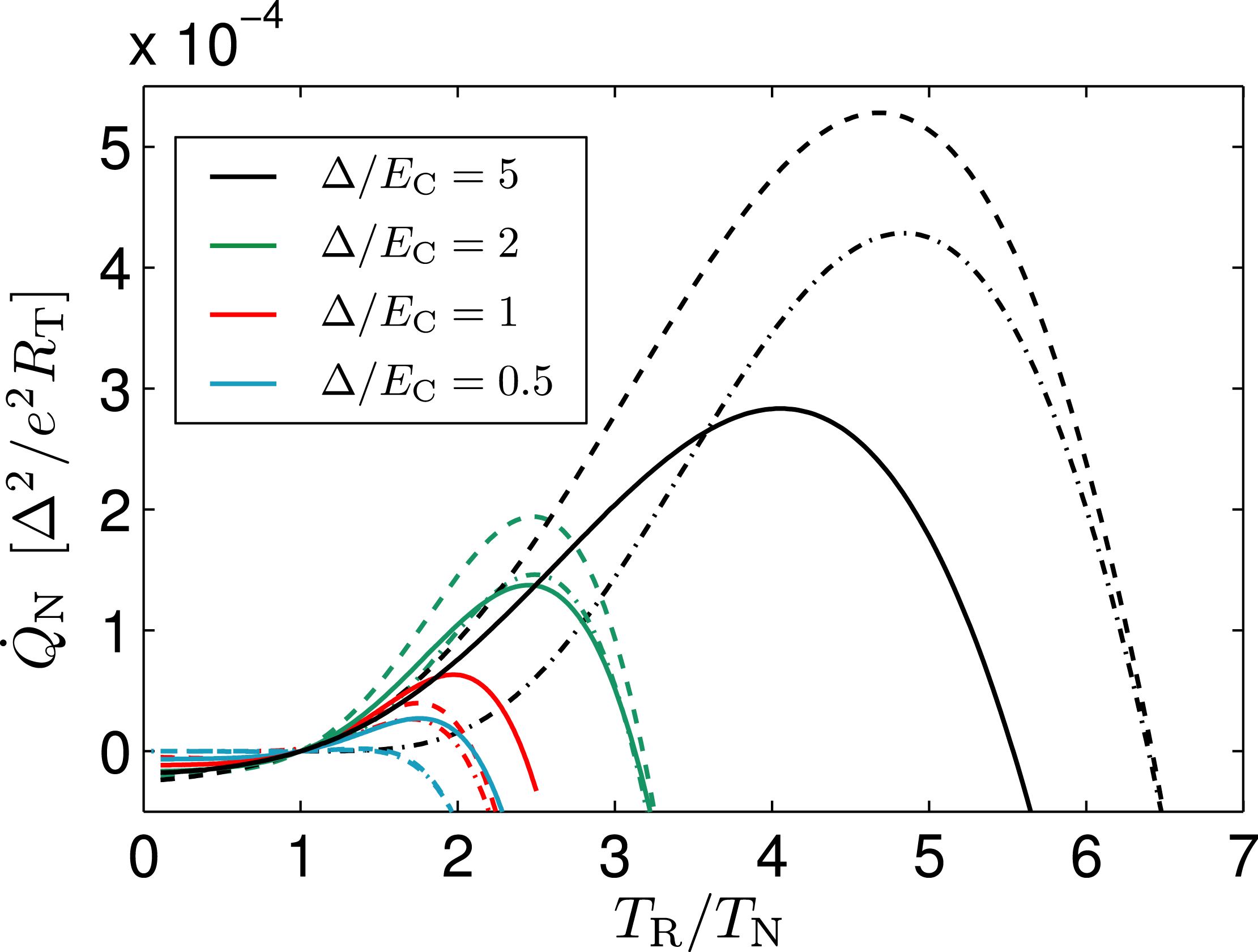
Figure 2: (color online) Cooling power Q˙Nsubscript˙𝑄N\dot{Q}_{\mathrm{N}} from Eq. (7) for R=10RK𝑅10subscript𝑅KR=10R_{\mathrm{K}} (dashed lines) and R=0.5RK𝑅0.5subscript𝑅KR=0.5R_{\mathrm{K}} (solid) at various values of Δ/ECΔsubscript𝐸C\Delta/E_{\mathrm{C}}. Notice that for Δ>ECΔsubscript𝐸C\Delta>E_{\mathrm{C}} better cooling power is obtained with large R𝑅R whereas for ΔECless-than-or-similar-toΔsubscript𝐸C\Delta\lesssim E_{\mathrm{C}} the larger cooling power is found with R=0.5RK𝑅0.5subscript𝑅KR=0.5R_{\mathrm{K}}. The R=10RK𝑅10subscript𝑅KR=10R_{\mathrm{K}} -curves fall below the R=0.5RK𝑅0.5subscript𝑅KR=0.5R_{\mathrm{K}} ones around Δ1.5ECΔ1.5subscript𝐸C\Delta\approx 1.5E_{\mathrm{C}}. The dash-dotted lines show the analytical approximation discussed in Appendix A, valid for RRKmuch-greater-than𝑅subscript𝑅KR\gg R_{\mathrm{K}} and kBTN2ECkBTRmuch-less-thansubscript𝑘Bsubscript𝑇N2subscript𝐸Csubscript𝑘Bsubscript𝑇Rk_{\mathrm{B}}T_{\mathrm{N}}\ll\sqrt{2E_{\mathrm{C}}k_{\mathrm{B}}T_{\mathrm{R}}}, and capturing most of the cooling effect.

The main result of Sec. II.1, Eq. (2), applies to a generic tunnel junction between conductors 111 and 222. An important special case is an NIS junction, where a BCS density of states with energy gap ΔΔ\Delta in S and approximately constant DoS in N near EFsubscript𝐸FE_{\mathrm{F}} make this system a particularly important example. In the following, we will consider the heat flows for an NIS junction with nN(E)1subscript𝑛N𝐸1n_{\mathrm{N}}(E)\equiv 1, and a smeared BCS DoS

nS(E)=|Re[E+iγ(E+iγ)2Δ2]|subscript𝑛S𝐸Redelimited-[]𝐸𝑖𝛾superscript𝐸𝑖𝛾2superscriptΔ2n_{\mathrm{S}}(E)=\left|\mathrm{Re}\left[\frac{E+i\gamma}{\sqrt{(E+i\gamma)^{2}-\Delta^{2}}}\right]\right| (6)

in the superconductor. Here, the small parameter γ𝛾\gamma describes the finite lifetime broadening of the ideally diverging BCS DoS at the gap edges dynes84 . In all the numerical calculations to follow, we assume Δ=200μeVΔ200𝜇eV\Delta=200\;\mu\mathrm{eV} (aluminum) and γ=1×10⁵Δ𝛾1superscript105Δ\gamma=1\times 10^{-5}\Delta, unless noted otherwise. We limit to low temperatures so that the temperature dependence of ΔΔ\Delta can be neglected. Assuming electrode 1 (2) to be of N (S) type in Eq. (2), we find explicitly

Q˙N=subscript˙𝑄Nabsent\displaystyle\dot{Q}_{\mathrm{N}}= 2e2RTdEdEnS(E)E×\displaystyle\frac{2}{e^{2}R_{\mathrm{T}}}\int_{-\infty}^{\infty}\int_{-\infty}^{\infty}dEdE^{\prime}n_{\mathrm{S}}(E^{\prime})E\times
fN(E)[1fS(E)]P(EE)subscript𝑓N𝐸delimited-[]1subscript𝑓Ssuperscript𝐸𝑃𝐸superscript𝐸\displaystyle f_{\mathrm{N}}(E)\left[1-f_{\mathrm{S}}(E^{\prime})\right]P(E-E^{\prime}) (7)

and

Q˙S=subscript˙𝑄Sabsent\displaystyle\dot{Q}_{\mathrm{S}}= 2e2RTdEdEnS(E)(E)×\displaystyle\frac{2}{e^{2}R_{\mathrm{T}}}\int_{-\infty}^{\infty}\int_{-\infty}^{\infty}dEdE^{\prime}n_{\mathrm{S}}(E^{\prime})(-E^{\prime})\times
fN(E)[1fS(E)]P(EE)subscript𝑓N𝐸delimited-[]1subscript𝑓Ssuperscript𝐸𝑃𝐸superscript𝐸\displaystyle f_{\mathrm{N}}(E)\left[1-f_{\mathrm{S}}(E^{\prime})\right]P(E-E^{\prime}) (8)

for the heat extracted from N and S, respectively. In Fig. 2 we compare the numerically calculated cooling powers Q˙Nsubscript˙𝑄N\dot{Q}_{\mathrm{N}} for R=10RK𝑅10subscript𝑅KR=10R_{\mathrm{K}} and R=0.5RK𝑅0.5subscript𝑅KR=0.5R_{\mathrm{K}} as a function of TR/TNsubscript𝑇Rsubscript𝑇NT_{\mathrm{R}}/T_{\mathrm{N}} at various charging energies ECsubscript𝐸CE_{\mathrm{C}}, i.e., capacitances C𝐶C. The temperatures are fixed to kBTN=kBTS=0.1Δsubscript𝑘Bsubscript𝑇Nsubscript𝑘Bsubscript𝑇S0.1Δk_{\mathrm{B}}T_{\mathrm{N}}=k_{\mathrm{B}}T_{\mathrm{S}}=0.1\Delta. Looking at the qualitative behavior of Q˙Nsubscript˙𝑄N\dot{Q}_{\mathrm{N}}, we notice that Q˙N>0subscript˙𝑄N0\dot{Q}_{\mathrm{N}}>0 in a large temperature range TN<TR<TRmaxsubscript𝑇Nsubscript𝑇Rsuperscriptsubscript𝑇RmaxT_{\mathrm{N}}<T_{\mathrm{R}}<T_{\mathrm{R}}^{\mathrm{max}}, indicating refrigeration of the normal metal. The maximum cooling power, Q˙Noptsuperscriptsubscript˙𝑄Nopt\dot{Q}_{\mathrm{N}}^{\mathrm{opt}}, depends on R𝑅R in a nontrivial manner, whereas the corresponding optimum resistor temperature TRopt/TNΔ/ECsimilar-to-or-equalssuperscriptsubscript𝑇Roptsubscript𝑇NΔsubscript𝐸CT_{\mathrm{R}}^{\mathrm{opt}}/T_{\mathrm{N}}\simeq\Delta/E_{\mathrm{C}} is sensitive mainly to the capacitance. We notice further that for Δ>ECΔsubscript𝐸C\Delta>E_{\mathrm{C}} better cooling power is obtained with large environmental resistances whereas for ΔECless-than-or-similar-toΔsubscript𝐸C\Delta\lesssim E_{\mathrm{C}} the larger cooling power is found with R=0.5RK𝑅0.5subscript𝑅KR=0.5R_{\mathrm{K}}. Comparing the Q˙Noptsuperscriptsubscript˙𝑄Nopt\dot{Q}_{\mathrm{N}}^{\mathrm{opt}}-values, the R=10RK𝑅10subscript𝑅KR=10R_{\mathrm{K}} -curves fall below the R=0.5RK𝑅0.5subscript𝑅KR=0.5R_{\mathrm{K}} ones around Δ1.5ECΔ1.5subscript𝐸C\Delta\approx 1.5E_{\mathrm{C}}. Above a certain circuit-dependent temperature TRmaxsuperscriptsubscript𝑇RmaxT_{\mathrm{R}}^{\mathrm{max}} the N island tends to heat up [Q˙N<0]delimited-[]subscript˙𝑄N0[\dot{Q}_{\mathrm{N}}<0], which happens non-trivially also in the regime TR<TNsubscript𝑇Rsubscript𝑇NT_{\mathrm{R}}<T_{\mathrm{N}}, i.e., heat flows into the “hot” normal metal island.
Refer to caption
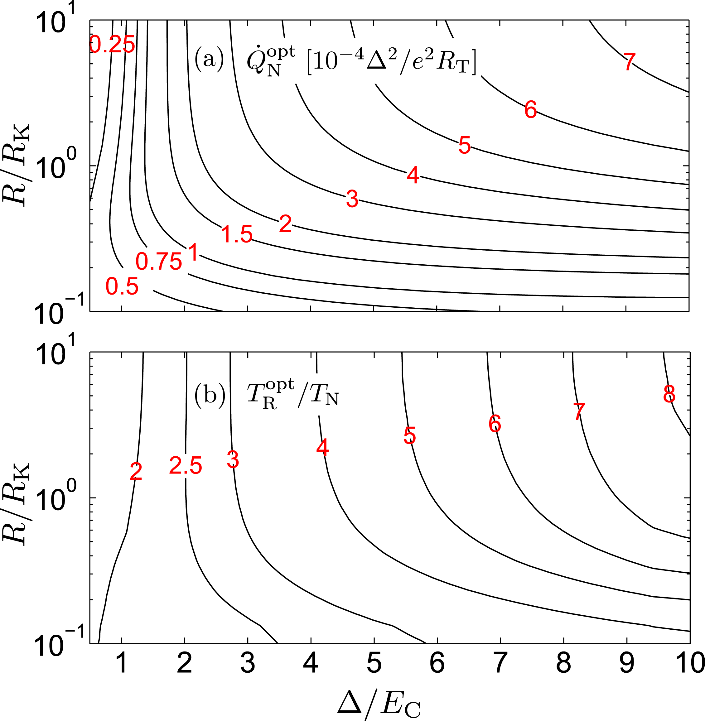
Figure 3: (color online) Maximum cooling power Q˙Noptsuperscriptsubscript˙𝑄Nopt\dot{Q}_{\mathrm{N}}^{\mathrm{opt}} (top) and the corresponding optimum resistor temperature TRoptsuperscriptsubscript𝑇RoptT_{\mathrm{R}}^{\mathrm{opt}} (bottom) as a function of R𝑅R and ECsubscript𝐸CE_{\mathrm{C}} at kBTN=kBTS=0.1Δsubscript𝑘Bsubscript𝑇Nsubscript𝑘Bsubscript𝑇S0.1Δk_{\mathrm{B}}T_{\mathrm{N}}=k_{\mathrm{B}}T_{\mathrm{S}}=0.1\Delta. At fixed R𝑅R, TRoptsuperscriptsubscript𝑇RoptT_{\mathrm{R}}^{\mathrm{opt}} increases approximately linearly as a function of Δ/ECΔsubscript𝐸C\Delta/E_{\mathrm{C}}, and starts to become independent of R𝑅R at RRKgreater-than-or-equivalent-to𝑅subscript𝑅KR\gtrsim R_{\mathrm{K}}.
Refer to caption
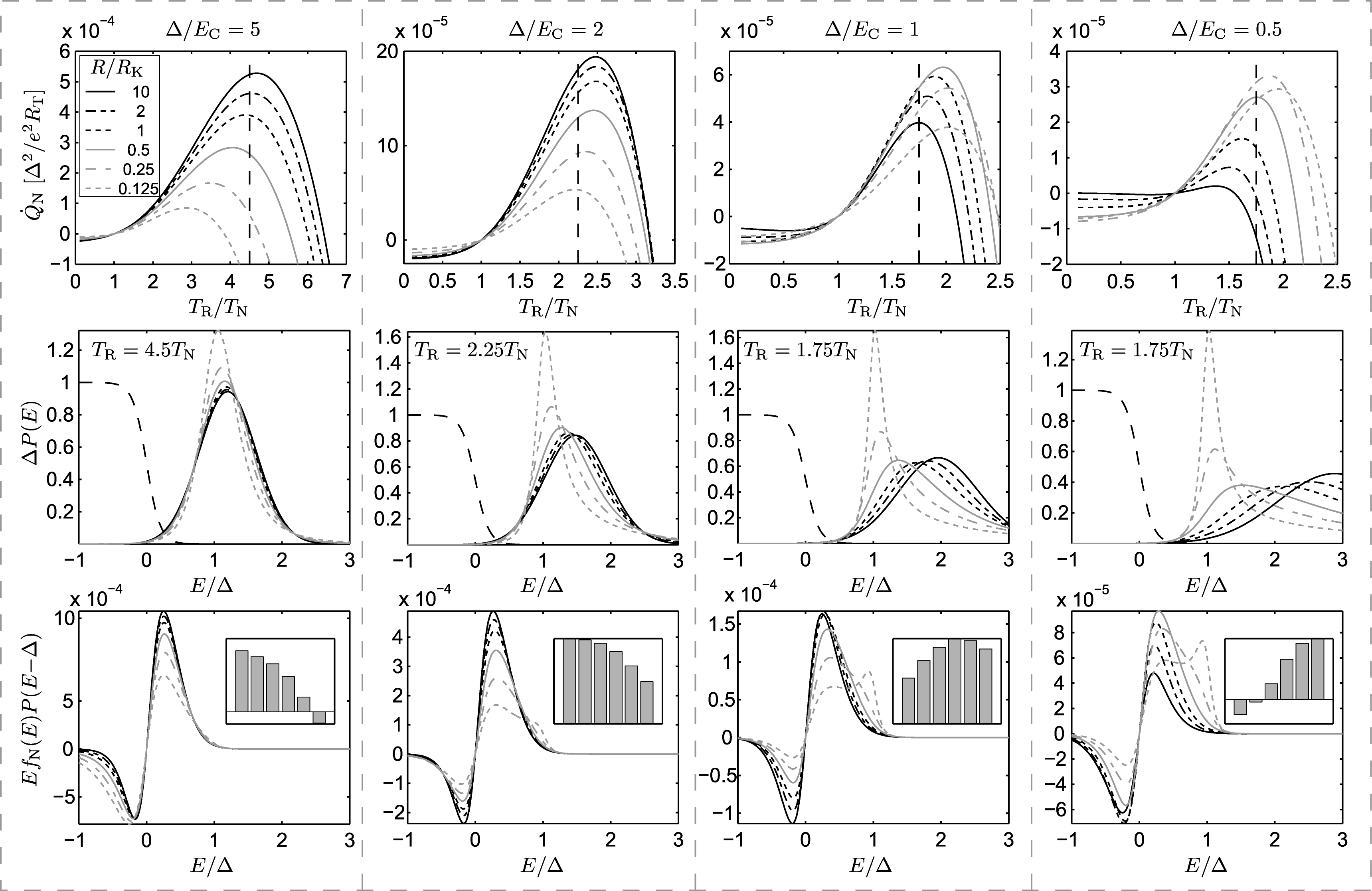
Figure 4: Top panels: Cooling power Q˙Nsubscript˙𝑄N\dot{Q}_{\mathrm{N}} at kBTN=kBTS=0.1Δsubscript𝑘Bsubscript𝑇Nsubscript𝑘Bsubscript𝑇S0.1Δk_{\mathrm{B}}T_{\mathrm{N}}=k_{\mathrm{B}}T_{\mathrm{S}}=0.1\Delta as a function of TRsubscript𝑇RT_{\mathrm{R}} for different resistances R/RK=10,,0.125𝑅subscript𝑅K100.125R/R_{\mathrm{K}}=10,\ldots,0.125. Each panel shows data at a fixed Δ/ECΔsubscript𝐸C\Delta/E_{\mathrm{C}}, decreasing from left to right. Middle: Fermi function fN(E)subscript𝑓N𝐸f_{\mathrm{N}}(E) (long dashes) and P(E)Δ𝑃𝐸ΔP(E)\Delta at the indicated fixed resistor temperature TRsubscript𝑇RT_{\mathrm{R}} marked also by the vertical dashed line in the top panels, for the same resistor values as in the top panels. Bottom: Overlap EfN(E)P(EΔ)𝐸subscript𝑓N𝐸𝑃𝐸ΔEf_{\mathrm{N}}(E)P(E-\Delta). The insets show F(Δ)=𝑑EEfN(E)P(EΔ)𝐹Δdifferential-d𝐸𝐸subscript𝑓N𝐸𝑃𝐸ΔF(\Delta)=\int dEEf_{\mathrm{N}}(E)P(E-\Delta) relative to the maximum F(Δ)𝐹ΔF(\Delta), with R𝑅R decreasing from left to right on the horizontal axis.

In Fig. 3 we plot the maximum cooling power and the corresponding optimum resistor temperature as a function of R𝑅R and ECsubscript𝐸CE_{\mathrm{C}}. As evident from Fig. 2, for small junctions with ECΔgreater-than-or-equivalent-tosubscript𝐸CΔE_{\mathrm{C}}\gtrsim\Delta the cooling power is maximized at finite values of R𝑅R, and at large R𝑅R the power Q˙Noptsuperscriptsubscript˙𝑄Nopt\dot{Q}_{\mathrm{N}}^{\mathrm{opt}} is very small for EC2Δgreater-than-or-equivalent-tosubscript𝐸C2ΔE_{\mathrm{C}}\gtrsim 2\Delta. Finally, the top panels in Fig. 4 shows more detailed plots of Q˙Nsubscript˙𝑄N\dot{Q}_{\mathrm{N}} as a function of TRsubscript𝑇RT_{\mathrm{R}} at several values of the resistance R𝑅R, with each panel assuming a fixed Δ/ECΔsubscript𝐸C\Delta/E_{\mathrm{C}}.

In Ref. pekola07, , two analytical approximations were derived for Q˙Nsubscript˙𝑄N\dot{Q}_{\mathrm{N}}, assuming an idealized high-impedance environment with RRKmuch-greater-than𝑅subscript𝑅KR\gg R_{\mathrm{K}} at a high enough temperature TRsubscript𝑇RT_{\mathrm{R}} to utilize a Gaussian P(E)𝑃𝐸P(E). The first of these results was based on replacing the Fermi functions by their Boltzmann-like exponential tails, valid at low temperatures kBTN,kBTSΔmuch-less-thansubscript𝑘Bsubscript𝑇Nsubscript𝑘Bsubscript𝑇SΔk_{\mathrm{B}}T_{\mathrm{N}},k_{\mathrm{B}}T_{\mathrm{S}}\ll\Delta. For the second approximation, the quadratic exponent of P(EE)𝑃𝐸superscript𝐸P(E-E^{\prime}) was linearized around E=0𝐸0E=0, whereas the correct form of fN(E)subscript𝑓N𝐸f_{\mathrm{N}}(E) was retained, resulting in a reasonable result for a wide range of TR/TNsubscript𝑇Rsubscript𝑇NT_{\mathrm{R}}/T_{\mathrm{N}}. In Appendix A we present another approximation valid at RRKmuch-greater-than𝑅subscript𝑅KR\gg R_{\mathrm{K}} and kBTNsmuch-less-thansubscript𝑘Bsubscript𝑇N𝑠k_{\mathrm{B}}T_{\mathrm{N}}\ll s, shown in Fig. 2 as the dash-dotted lines. This is based on first performing a Sommerfeld expansion of the E𝐸E-integral in Eq. 7 in terms of kBTN/ssubscript𝑘Bsubscript𝑇N𝑠k_{\mathrm{B}}T_{\mathrm{N}}/s, and treating the remaining integral over Esuperscript𝐸E^{\prime} as in the second approximation in Ref. pekola07, .

Since the S DoS is strongly peaked at the gap edge as evident from Eq. (6), electrons tunneling out of N end up mainly at energies near this threshold. Therefore, to understand qualitatively the behavior of Q˙Nsubscript˙𝑄N\dot{Q}_{\mathrm{N}} in Fig. 2, we may evaluate the integrand in Eq. (7) only at superconductor energies E=±Δsuperscript𝐸plus-or-minusΔE^{\prime}=\pm\Delta, see Fig. 4 middle and bottom panels: Looking at the dimensionless quantities

F(±Δ)=𝑑EEfN(E)P(EΔ)𝐹plus-or-minusΔsuperscriptsubscriptdifferential-d𝐸𝐸subscript𝑓N𝐸𝑃minus-or-plus𝐸ΔF(\pm\Delta)=\int_{-\infty}^{\infty}dEEf_{\mathrm{N}}(E)P(E\mp\Delta) (9)

we find that the cooling power depends on the overlap of the tail of Fermi function and P(EΔ)𝑃minus-or-plus𝐸ΔP(E\mp\Delta). At high temperatures TR>TRmaxsubscript𝑇Rsuperscriptsubscript𝑇RmaxT_{\mathrm{R}}>T_{\mathrm{R}}^{\mathrm{max}}, P(EΔ)𝑃𝐸ΔP(E-\Delta) is broad, and negative contributions from E<0𝐸0E<0 outweigh those from E>0𝐸0E>0. This corresponds to low energy electrons from below the Fermi level tunneling to the gap edge in S. As a result, the dominant quantity F(Δ)𝐹ΔF(\Delta) and therefore Q˙Nsubscript˙𝑄N\dot{Q}_{\mathrm{N}} turn negative. At TNTR<TRmaxless-than-or-similar-tosubscript𝑇Nsubscript𝑇Rsuperscriptsubscript𝑇RmaxT_{\mathrm{N}}\lesssim T_{\mathrm{R}}<T_{\mathrm{R}}^{\mathrm{max}} the positive contributions outweigh the negative ones, resulting in a net cooling effect. Finally, at TRTN,TSmuch-less-thansubscript𝑇Rsubscript𝑇Nsubscript𝑇ST_{\mathrm{R}}\ll T_{\mathrm{N}},T_{\mathrm{S}}, P(E)𝑃𝐸P(E) is very sharp, and mainly E<0𝐸0E<0 in F(Δ)𝐹ΔF(-\Delta) contribute via P(E+Δ)𝑃𝐸ΔP(E+\Delta), leading to Q˙N<0subscript˙𝑄N0\dot{Q}_{\mathrm{N}}<0.

III Entropy flow

In the previous section we saw that heat can flow out of the N electrode when the resistor is held at temperature TR>TNsubscript𝑇Rsubscript𝑇NT_{\mathrm{R}}>T_{\mathrm{N}}. Similarly, the S tends to cool for TR<TNsubscript𝑇Rsubscript𝑇NT_{\mathrm{R}}<T_{\mathrm{N}}. Here we extend the analysis of Ref. pekola07, , showing explicitly that the system obeys the second law of thermodynamics despite the counter-intuitive heat fluxes. We consider the total entropy production for a single NIS junction in an arbitrary equilibrium environment (“resistor”) obeying detailed balance, showing explicitly that it is always increasing. In the following we assume the NIS junction and the resistor to form an isolated system and ignore couplings to the phonon bath. Let S˙˙𝑆\dot{S} be the rate of entropy production in the system composed of N, S and R, at temperatures TNsubscript𝑇NT_{\mathrm{N}}, TSsubscript𝑇ST_{\mathrm{S}}, and TRsubscript𝑇RT_{\mathrm{R}}, respectively. In general, the energy conservation Q˙N+Q˙S+Q˙R=0subscript˙𝑄Nsubscript˙𝑄Ssubscript˙𝑄R0\dot{Q}_{\mathrm{N}}+\dot{Q}_{\mathrm{S}}+\dot{Q}_{\mathrm{R}}=0 holds, as discussed after Eq. (2). In addition, we have the definition S˙=Q˙N/TNQ˙S/TSQ˙R/TR˙𝑆subscript˙𝑄Nsubscript𝑇Nsubscript˙𝑄Ssubscript𝑇Ssubscript˙𝑄Rsubscript𝑇R\dot{S}=-\dot{Q}_{\mathrm{N}}/T_{\mathrm{N}}-\dot{Q}_{\mathrm{S}}/T_{\mathrm{S}}-\dot{Q}_{\mathrm{R}}/T_{\mathrm{R}}. We consider the general case of three unequal temperatures kBTN=βN1subscript𝑘Bsubscript𝑇Nsuperscriptsubscript𝛽N1k_{\mathrm{B}}T_{\mathrm{N}}=\beta_{\mathrm{N}}^{-1}, kBTS=βS1subscript𝑘Bsubscript𝑇Ssuperscriptsubscript𝛽S1k_{\mathrm{B}}T_{\mathrm{S}}=\beta_{\mathrm{S}}^{-1}, and kBTR=βR1subscript𝑘Bsubscript𝑇Rsuperscriptsubscript𝛽R1k_{\mathrm{B}}T_{\mathrm{R}}=\beta_{\mathrm{R}}^{-1}. The above results can be combined to yield S˙/kB=(βRβN)Q˙N+(βRβS)Q˙S˙𝑆subscript𝑘Bsubscript𝛽Rsubscript𝛽Nsubscript˙𝑄Nsubscript𝛽Rsubscript𝛽Ssubscript˙𝑄S\dot{S}/k_{\mathrm{B}}=(\beta_{\mathrm{R}}-\beta_{\mathrm{N}})\dot{Q}_{\mathrm{N}}+(\beta_{\mathrm{R}}-\beta_{\mathrm{S}})\dot{Q}_{\mathrm{S}}. We find

S˙=2kBe2RT0dEP(E)0dEnS(E)×{.\displaystyle\dot{S}=\frac{2k_{\mathrm{B}}}{e^{2}R_{\mathrm{T}}}\int_{0}^{\infty}dE^{\prime}P(E^{\prime})\int_{0}^{\infty}dEn_{\mathrm{S}}(E)\times\bigg{\{}\big{.} (10)
(βRβN)E[fN(E+E)eβREfN(EE)+\displaystyle(\beta_{\mathrm{R}}-\beta_{\mathrm{N}})E^{\prime}\left[\right.f_{\mathrm{N}}(E+E^{\prime})-e^{-\beta_{\mathrm{R}}E^{\prime}}f_{\mathrm{N}}(E-E^{\prime})+
fS(E)(1eβRE)(1fN(E+E)fN(EE))]+\displaystyle f_{\mathrm{S}}(E)(1-e^{-\beta_{\mathrm{R}}E^{\prime}})\left(1-f_{\mathrm{N}}\left(E+E^{\prime}\right)-f_{\mathrm{N}}\left(E-E^{\prime}\right)\right)\left.\right]+
(βSβN)E[.fN(E+E)+eβREfN(EE)+fS(E)×\displaystyle(\beta_{\mathrm{S}}-\beta_{\mathrm{N}})E\bigg{[}\bigg{.}f_{\mathrm{N}}(E+E^{\prime})+e^{-\beta_{\mathrm{R}}E^{\prime}}f_{\mathrm{N}}(E-E^{\prime})+f_{\mathrm{S}}(E)\times
[(1eβRE)(fN(EE)fN(E+E))1eβRE].].}.\displaystyle[(1-e^{-\beta_{\mathrm{R}}E^{\prime}})\left(f_{\mathrm{N}}\left(E-E^{\prime}\right)-f_{\mathrm{N}}\left(E+E^{\prime}\right)\right)-1-e^{-\beta_{\mathrm{R}}E^{\prime}}]\bigg{.}\bigg{]}\bigg{.}\bigg{\}}.

Here, we utilized the detailed balance of P(E)𝑃superscript𝐸P(E^{\prime}), and the symmetry nS(E)=nS(E)subscript𝑛S𝐸subscript𝑛S𝐸n_{\mathrm{S}}(-E)=n_{\mathrm{S}}(E) of the S DoS. This equation should hold for any form of positive P(E)𝑃superscript𝐸P(E^{\prime}) and (symmetric) nS(E)subscript𝑛S𝐸n_{\mathrm{S}}(E). In order to show that S˙>0˙𝑆0\dot{S}>0 we have therefore to demonstrate that the integrand \mathcal{I} on the last four lines in Eq. (10) is positive for any value of E𝐸E, Esuperscript𝐸E^{\prime}, βNsubscript𝛽N\beta_{\mathrm{N}}, βSsubscript𝛽S\beta_{\mathrm{S}}, and βRsubscript𝛽R\beta_{\mathrm{R}}.

In the following we assume the distribution functions in N and S to be of the equilibrium form fi(E)=1/(1+eβiE)subscript𝑓𝑖𝐸11superscript𝑒subscript𝛽𝑖𝐸f_{i}(E)=1/(1+e^{\beta_{i}E}). After straightforward manipulations [see Appendix B for details], the last four lines in Eq. (10) transform into

=N𝒮(e𝒳1)𝒳+N𝒜(e𝒴1)𝒴.subscript𝑁𝒮superscript𝑒𝒳1𝒳subscript𝑁𝒜superscript𝑒𝒴1𝒴\mathcal{I}=N_{\mathcal{S}}(e^{\mathcal{X}}-1)\mathcal{X}+N_{\mathcal{A}}\left(e^{\mathcal{Y}}-1\right)\mathcal{Y}. (11)

Here, the quantities

N𝒮subscript𝑁𝒮\displaystyle N_{\mathcal{S}} =eβREeβN(E+E)(1+eβSE)(1+eβN(E+E))andabsentsuperscript𝑒subscript𝛽Rsuperscript𝐸superscript𝑒subscript𝛽N𝐸superscript𝐸1superscript𝑒subscript𝛽S𝐸1superscript𝑒subscript𝛽N𝐸superscript𝐸and\displaystyle=\frac{e^{-\beta_{\mathrm{R}}E^{\prime}}e^{\beta_{\mathrm{N}}(E+E^{\prime})}}{(1+e^{\beta_{\mathrm{S}}E})(1+e^{\beta_{\mathrm{N}}(E+E^{\prime})})}\quad\mathrm{and} (12)
N𝒜subscript𝑁𝒜\displaystyle N_{\mathcal{A}} =eβN(EE)(eβN(EE)+1)(1+eβSE)absentsuperscript𝑒subscript𝛽N𝐸superscript𝐸superscript𝑒subscript𝛽N𝐸superscript𝐸11superscript𝑒subscript𝛽S𝐸\displaystyle=\frac{e^{\beta_{\mathrm{N}}(E-E^{\prime})}}{(e^{\beta_{\mathrm{N}}(E-E^{\prime})}+1)(1+e^{\beta_{\mathrm{S}}E})} (13)

are always positive. We also defined the combinations 𝒳=(βSβN)E+(βRβN)E𝒳subscript𝛽Ssubscript𝛽N𝐸subscript𝛽Rsubscript𝛽Nsuperscript𝐸\mathcal{X}=(\beta_{\mathrm{S}}-\beta_{\mathrm{N}})E+(\beta_{\mathrm{R}}-\beta_{\mathrm{N}})E^{\prime} and 𝒴=(βSβN)E(βRβN)E𝒴subscript𝛽Ssubscript𝛽N𝐸subscript𝛽Rsubscript𝛽Nsuperscript𝐸\mathcal{Y}=\left(\beta_{\mathrm{S}}-\beta_{\mathrm{N}}\right)E-\left(\beta_{\mathrm{R}}-\beta_{\mathrm{N}}\right)E^{\prime}. Now, for any value of 𝒳𝒳\mathcal{X} and 𝒴𝒴\mathcal{Y}, the functions (e𝒳1)𝒳superscript𝑒𝒳1𝒳(e^{\mathcal{X}}-1)\mathcal{X} and (e𝒴1)𝒴superscript𝑒𝒴1𝒴\left(e^{\mathcal{Y}}-1\right)\mathcal{Y} in Eq. (11) are positive or zero. Thus, since N𝒮subscript𝑁𝒮N_{\mathcal{S}} and N𝒜subscript𝑁𝒜N_{\mathcal{A}} are always positive, we find that 00\mathcal{I}\geq 0 for any value of 𝒳𝒳\mathcal{X} and 𝒴𝒴\mathcal{Y}, and hence S˙0˙𝑆0\dot{S}\geq 0 always. Furthermore, at the special point βR=βN=βSsubscript𝛽Rsubscript𝛽Nsubscript𝛽S\beta_{\mathrm{R}}=\beta_{\mathrm{N}}=\beta_{\mathrm{S}}, we have Q˙N=Q˙S=0subscript˙𝑄Nsubscript˙𝑄S0\dot{Q}_{\mathrm{N}}=\dot{Q}_{\mathrm{S}}=0. Differentiating S˙˙𝑆\dot{S} then gives S˙βi=0˙𝑆subscript𝛽𝑖0\frac{\partial\dot{S}}{\partial\beta_{i}}=0, and we conclude that this point yields a local extremum (minimum) of S˙˙𝑆\dot{S}, and at this point S˙=0˙𝑆0\dot{S}=0 always. We have therefore shown that the entropy of the system is increasing for arbitrary values of TNsubscript𝑇NT_{\mathrm{N}}, TSsubscript𝑇ST_{\mathrm{S}}, and TSsubscript𝑇ST_{\mathrm{S}}. The procedure can be generalized to include a phonon bath at temperature T0subscript𝑇0T_{0}, in which case one considers the total system of N, S, R, and the phonons.

IV Noise cooling in two-junction SINIS with Coulomb interaction
Refer to caption
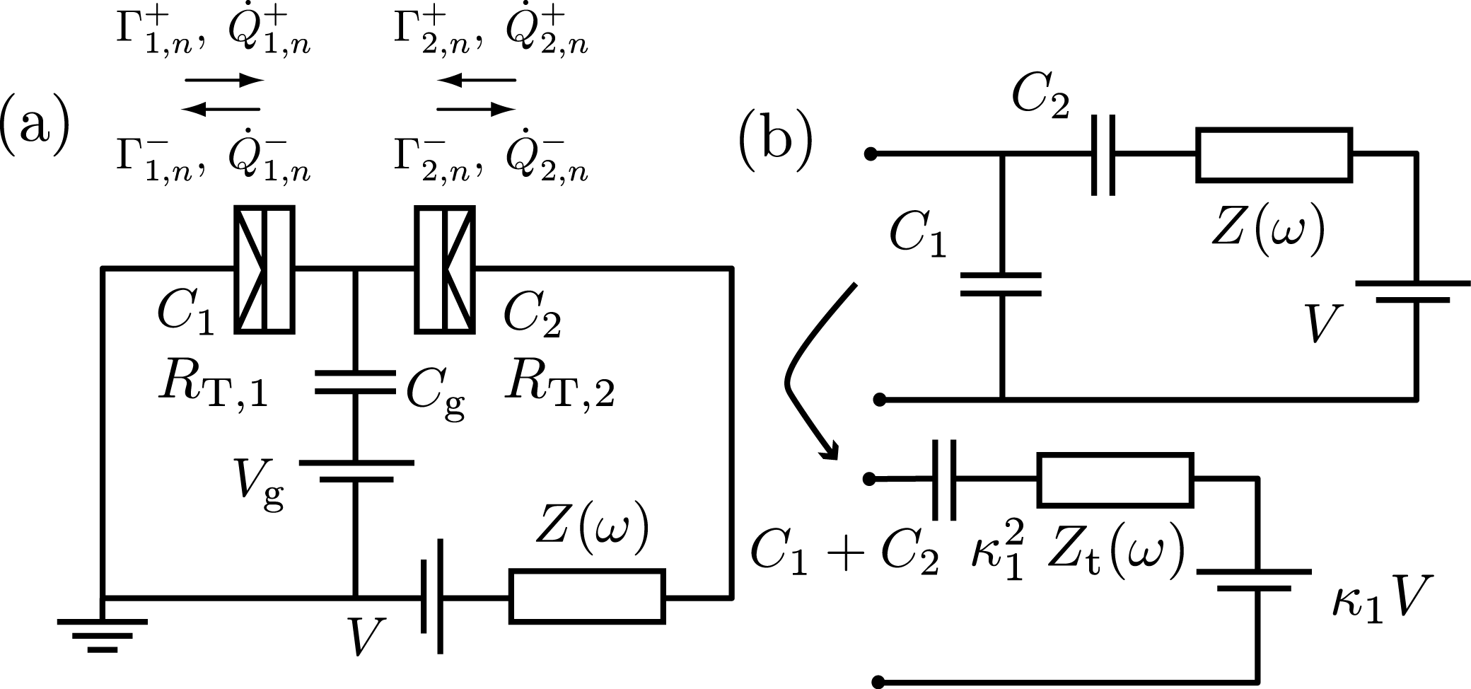
Figure 5: (a)a\left(\mathrm{a}\right)\;Hybrid single electron transistor in the presence of an environment, modeled as an impedance Z(ω)𝑍𝜔Z(\omega) in series with the bias voltage source V. A gate voltage Vgsubscript𝑉gV_{\mathrm{g}} is coupled capacitively to the N island via Cgsubscript𝐶gC_{\mathrm{g}}. The arrows define tunneling rates and heat fluxes for each of the two NIS junctions, with tunneling resistance RT,isubscript𝑅T𝑖R_{\mathrm{T},i} and capacitance Cisubscript𝐶𝑖C_{i} (i=1,2)𝑖12(i=1,2). (b)b\left(\mathrm{b}\right)\;Transformation of the environment seen from junction 1 into an effective single junction circuit.
Refer to caption
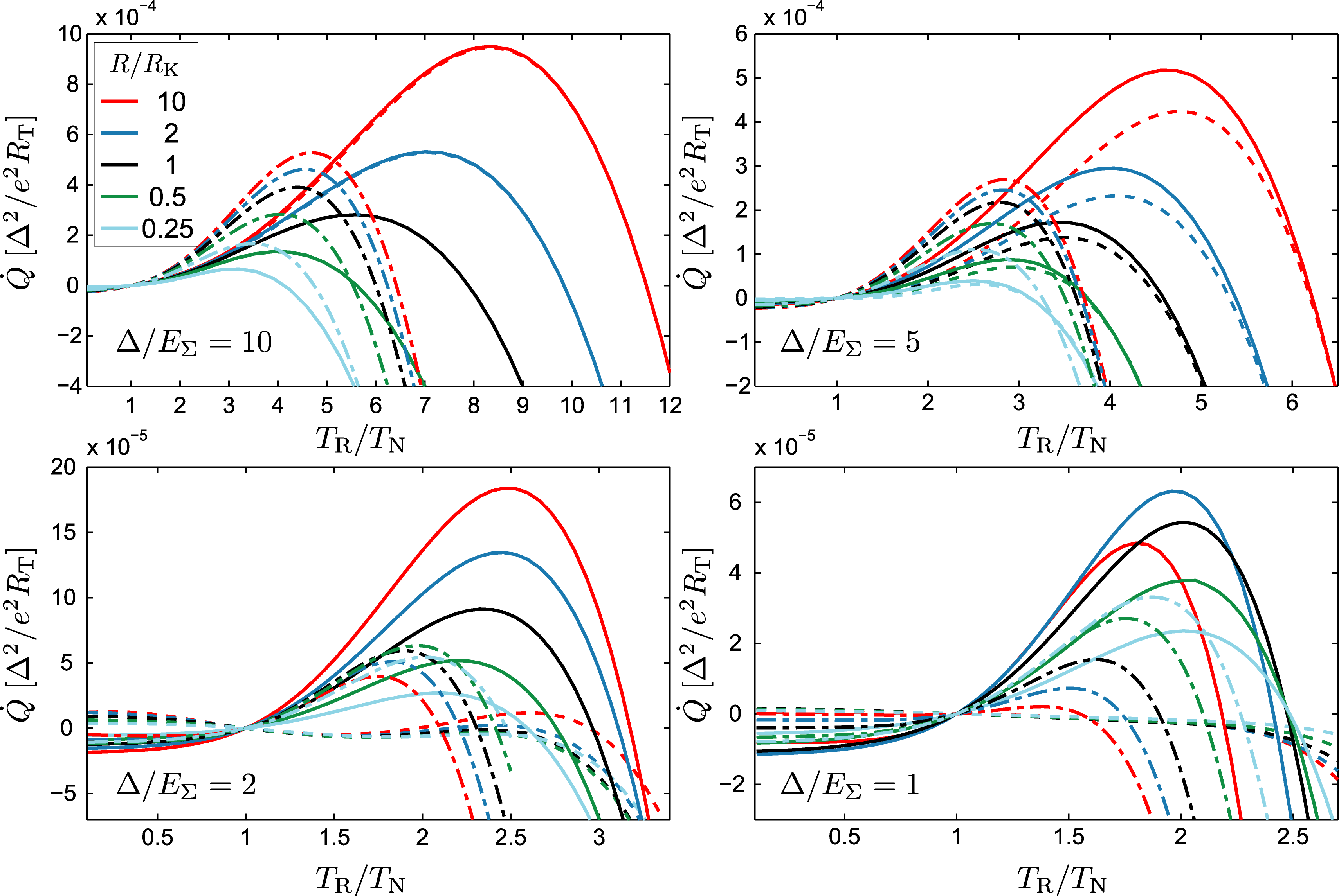
Figure 6: (color online) Noise-induced cooling power Q˙˙𝑄\dot{Q} in a SINIS structure for different charging energies EΣsubscript𝐸ΣE_{\Sigma}. Solid lines correspond to ng=0.5subscript𝑛g0.5n_{\mathrm{g}}=0.5 (“gate open”), and dashed lines to ng=0subscript𝑛g0n_{\mathrm{g}}=0 (“gate closed”). Dash-dotted lines indicate the cooling power of a single NIS junction, showing the influence of the effective circuit parameters Csuperscript𝐶C^{*} (in general, optimum cooling shifts towards larger TRsubscript𝑇RT_{\mathrm{R}} in the SINIS) and Rsuperscript𝑅R^{*} (cooling power power per junction is reduced in the SINIS for large Δ/EΣΔsubscript𝐸Σ\Delta/E_{\Sigma} and increased for small Δ/EΣΔsubscript𝐸Σ\Delta/E_{\Sigma}).

In this section we analyze the refrigeration effect combined with charging effects in a double junction SINIS configuration, i.e., a hybrid single electron transistor (SET) with a small N island connected to S leads via two tunnel junctions of the NIS type. Figure 5 (a)a\left(\mathrm{a}\right)\;shows such a SINIS structure coupled to a general environment Z(ω)𝑍𝜔Z(\omega), and the various tunneling rates in the system. The two junctions are assumed to be characterized by resistances RT,isubscript𝑅T𝑖R_{\mathrm{T},i} and capacitances Cisubscript𝐶𝑖C_{i} (i=1,2)𝑖12(i=1,2). We assume charge equilibrium to be reached before each tunneling event, so that the state of the system can be characterized by n𝑛n, the number of excess electrons on the island. The allowed values of n𝑛n can be controlled by the gate voltage Vgsubscript𝑉gV_{\mathrm{g}} coupled capacitively to the island via Cgsubscript𝐶gC_{\mathrm{g}}. We assume the gate capacitance Cgsubscript𝐶gC_{\mathrm{g}} to be much smaller than the junction capacitances but the voltage Vgsubscript𝑉gV_{\mathrm{g}} to be large enough so that the only effect of the gate is an offset ng=CgVg/esubscript𝑛gsubscript𝐶gsubscript𝑉g𝑒n_{\mathrm{g}}=C_{\mathrm{g}}V_{\mathrm{g}}/e to the island charge. Following Refs. ingold92, grabert91, , and ingold91, , it is straightforward to calculate numerically the net heat flux Q˙˙𝑄\dot{Q} out of the island in terms of the heat fluxes Q˙i,n±superscriptsubscript˙𝑄𝑖𝑛plus-or-minus\dot{Q}_{i,n}^{\pm} through junction i𝑖i with the island in state n𝑛n. This is accomplished by solving a steady state master equation that gives the occupation probability of each charge state n𝑛n, determined by the tunneling rates Γi,n±superscriptsubscriptΓ𝑖𝑛plus-or-minus\Gamma_{i,n}^{\pm}.

The difference to the case of a single junction in an environment becomes evident in Fig. 5 (b)b\left(\mathrm{b}\right). We neglect cotunneling effects and assume the tunneling events to be uncorrelated, so that the other junction can be viewed simply as a series capacitor. Concentrating on tunneling in junction 1, the upper half of Fig. 5 (b)b\left(\mathrm{b}\right)\;displays the circuit of Fig. 5 (a)a\left(\mathrm{a}\right)\;as seen from junction 1. It can be transformed ingold92 into an equivalent single junction circuit shown in the lower half, consisting firstly of an effective impedance κ12Zt(ω)superscriptsubscript𝜅12subscript𝑍t𝜔\kappa_{1}^{2}Z_{\mathrm{t}}(\omega) where Zt(ω)subscript𝑍t𝜔Z_{\mathrm{t}}(\omega) is as in Eq. (5), but defined in terms of the series capacitance C~=C1C2/(C1+C2)~𝐶subscript𝐶1subscript𝐶2subscript𝐶1subscript𝐶2\tilde{C}=C_{1}C_{2}/(C_{1}+C_{2}), i.e., Zt(ω)=1/(iωC~+Z1(ω))subscript𝑍t𝜔1𝑖𝜔~𝐶superscript𝑍1𝜔Z_{\mathrm{t}}(\omega)=1/(i\omega\tilde{C}+Z^{-1}(\omega)). The reduction factors κi=C~/Ci<1subscript𝜅𝑖~𝐶subscript𝐶𝑖1\kappa_{i}=\tilde{C}/C_{i}<1, (i=1,2)𝑖12(i=1,2) show the weakened effect of the external impedance Z(ω)𝑍𝜔Z(\omega) due to shielding by the second junction capacitance. In addition, the transformed circuit contains a capacitance C1+C2subscript𝐶1subscript𝐶2C_{1}+C_{2} and a voltage source with voltage κ1Vsubscript𝜅1𝑉\kappa_{1}V. The series capacitance does not influence the real part of the total external impedance, and for Brownian refrigeration we consider only V=0𝑉0V=0 in the end. The circuit for junction 2 is identical, except κ1subscript𝜅1\kappa_{1} is replaced by κ2subscript𝜅2\kappa_{2} and the voltage V𝑉V is inverted. Apart from charging effects, in the important special case of Z(ω)=R𝑍𝜔𝑅Z(\omega)=R and identical junctions (RT,1=RT,2=Rsubscript𝑅T1subscript𝑅T2𝑅R_{\mathrm{T},1}=R_{\mathrm{T},2}=R, C1=C2=Csubscript𝐶1subscript𝐶2𝐶C_{1}=C_{2}=C), we can directly apply the analysis of Sec. II to the double junction system if the resistance is replaced by R=R/4superscript𝑅𝑅4R^{*}=R/4 and the capacitance by C=2Csuperscript𝐶2𝐶C^{*}=2C.

Each panel in Fig. 6 displays the total cooling power Q˙˙𝑄\dot{Q} out of the N island as a function of TR/TNsubscript𝑇Rsubscript𝑇NT_{\mathrm{R}}/T_{\mathrm{N}} for various values of the resistance R/RK𝑅subscript𝑅KR/R_{\mathrm{K}} at the extreme values of the gate charge ngsubscript𝑛gn_{\mathrm{g}}, while the different panels correspond to different charging energies EΣ=e2/(2CΣ)subscript𝐸Σsuperscript𝑒22subscript𝐶ΣE_{\Sigma}=e^{2}/(2C_{\Sigma}) of the SINIS structure. We denote the total capacitance by CΣ=C1+C2subscript𝐶Σsubscript𝐶1subscript𝐶2C_{\Sigma}=C_{1}+C_{2}, and assume a symmetric structure with RT,1=RT,2=Rsubscript𝑅T1subscript𝑅T2𝑅R_{\mathrm{T},1}=R_{\mathrm{T},2}=R and C1=C2=Csubscript𝐶1subscript𝐶2𝐶C_{1}=C_{2}=C. As expected, in a SINIS with large junctions (Δ/EΣ10greater-than-or-equivalent-toΔsubscript𝐸Σ10\Delta/E_{\Sigma}\gtrsim 10), the charging effects do not affect the cooling power. In contrast, with smaller junctions (Δ/EΣ2less-than-or-similar-toΔsubscript𝐸Σ2\Delta/E_{\Sigma}\lesssim 2) the cooling power depends strongly on the gate charge ngsubscript𝑛gn_{\mathrm{g}}. As a consequence of rescaling the circuit parameters in the SINIS configuration, better cooling power per junction is achieved, in general, with a single NIS junction when compared to SINIS with two junctions of the same size. However, with small junctions (Δ/EΣ2less-than-or-similar-toΔsubscript𝐸Σ2\Delta/E_{\Sigma}\lesssim 2) greater cooling power can be reached in the SINIS circuit. Interestingly, in the “gate closed” position (ng=0subscript𝑛g0n_{\mathrm{g}}=0, maximum Coulomb blockade in a voltage biased SET), we find nontrivial solutions for the heat fluxes for small junctions. Especially in the SINIS structure with Δ/EΣ=2Δsubscript𝐸Σ2\Delta/E_{\Sigma}=2, the gate voltage is seen to reverse the heat fluxes instead of only suppressing them close to zero in the “gate closed” position. Single-electron effects in zero voltage-bias refrigeration in an NIS junction are discussed also in Ref. pekola07b, . There, the influence of a deterministic radio-frequency signal applied to the gate was analyzed, assuming negligible effect from the environment [P(E)=δ(E)𝑃𝐸𝛿𝐸P(E)=\delta(E)]. With ultrasmall tunnel junctions in general, the electronic refrigeration is sensitive to single-electron effects.
Refer to caption
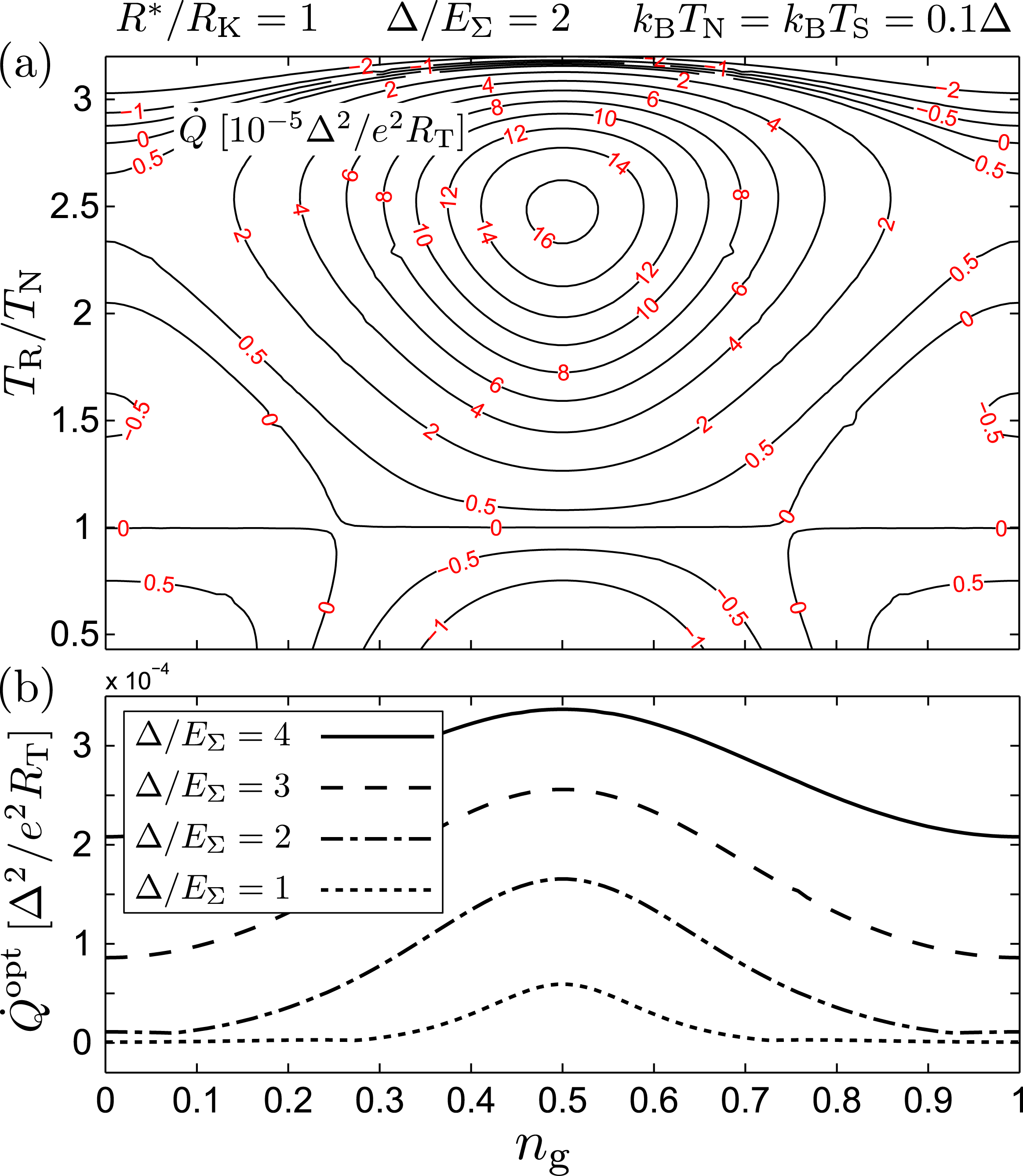
Figure 7: (color online) (a)a\left(\mathrm{a}\right)\;Contour plot of the cooling power in a symmetric SINIS structure as a function of the gate charge and the resistor temperature. (b)b\left(\mathrm{b}\right)\;Gate modulation of the maximum cooling power for four different charging energies.

Figure 7 emphasizes the gate dependence of Q˙˙𝑄\dot{Q}, already evident in Fig. 6. The contour plot in panel (a)a\left(\mathrm{a}\right)\;shows the total cooling power as a function of both the gate charge ngsubscript𝑛gn_{\mathrm{g}} and the resistor temperature TRsubscript𝑇RT_{\mathrm{R}}, at fixed kBTN=kBTS=0.1Δsubscript𝑘Bsubscript𝑇Nsubscript𝑘Bsubscript𝑇S0.1Δk_{\mathrm{B}}T_{\mathrm{N}}=k_{\mathrm{B}}T_{\mathrm{S}}=0.1\Delta. The calculation assumes identical junctions, Δ/EΣ=2Δsubscript𝐸Σ2\Delta/E_{\Sigma}=2, and a fixed R=RK𝑅subscript𝑅KR=R_{\mathrm{K}}. Finally, Fig. 7 (b)b\left(\mathrm{b}\right)\;shows the gate-dependent maximum cooling power of SINIS structures with Δ/EΣ=4, 3, 2,and 1Δsubscript𝐸Σ432and1\Delta/E_{\Sigma}=4,\;3,\;2,\;\mathrm{and}\;1.

V Other types of dissipative environments

Up to this point the environment parallel to the junction capacitance was assumed to be purely ohmic with Z(ω)=R𝑍𝜔𝑅Z(\omega)=R independent of frequency. In this section we analyze three examples of frequency dependent Z(ω)𝑍𝜔Z(\omega). These include a lumped inductance in series with the hot resistor, a distributed model treating the resistor as an RLC transmission line, and finally a lumped resistor connected to the junction via a lossless LC transmission line.

Refer to caption
Figure 8: (color online) Models for non-ohmic junction environments. (a)a\left(\mathrm{a}\right)\;Junction environment formed by an inductance L𝐿L in series with the resistance R𝑅R. (b)b\left(\mathrm{b}\right)\;Symmetric distributed model showing the transformation to two standard transmission lines.

V.1 Series inductance

Refer to caption
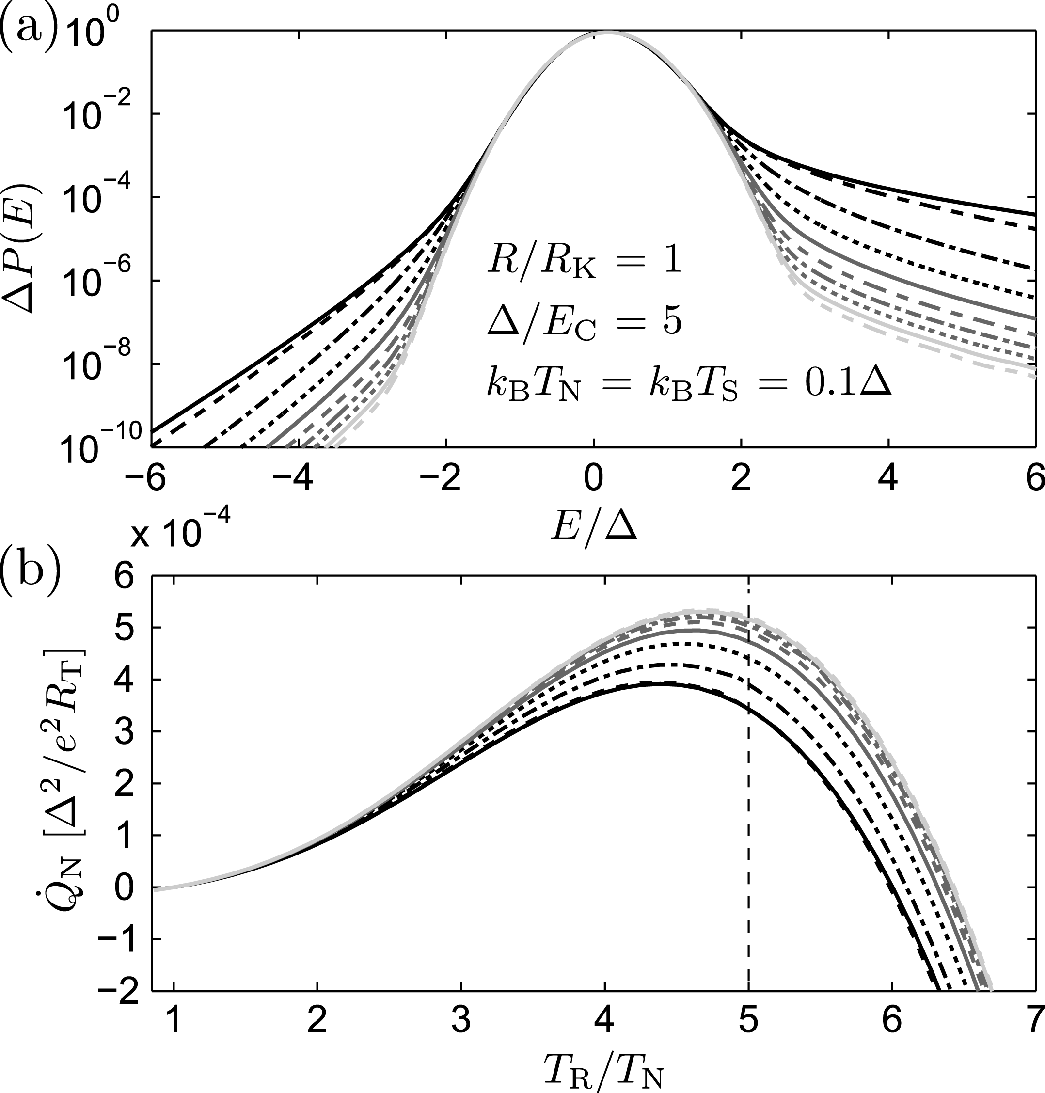
Figure 9: (a)a\left(\mathrm{a}\right)\;P(E)𝑃𝐸P(E) at TR=5TNsubscript𝑇R5subscript𝑇NT_{\mathrm{R}}=5T_{\mathrm{N}} for ten evenly spaced values of Q𝑄Q between 0 and 1, with the thick black line denoting the case Q=0𝑄0Q=0 (pure RC circuit). (b)b\left(\mathrm{b}\right)\;Cooling power Q˙Nsubscript˙𝑄N\dot{Q}_{\mathrm{N}} as a function of TRsubscript𝑇RT_{\mathrm{R}} at R=RK𝑅subscript𝑅KR=R_{\mathrm{K}}, Δ/EC=5Δsubscript𝐸C5\Delta/E_{\mathrm{C}}=5, and kBTN/Δ=0.1subscript𝑘Bsubscript𝑇NΔ0.1k_{\mathrm{B}}T_{\mathrm{N}}/\Delta=0.1 for the same values of Q𝑄Q as in (a)a\left(\mathrm{a}\right).

If an inductance L𝐿L connects the environmental resistance R𝑅R to the junction capacitance C𝐶C as in the inset of Fig. 9 (b)b\left(\mathrm{b}\right), the total impedance is given by

Zt(ω)RK=RRK1+iQ2(ω/ωR)1+i(ω/ωR)Q2(ω/ωR)2,subscript𝑍t𝜔subscript𝑅K𝑅subscript𝑅K1𝑖superscript𝑄2𝜔subscript𝜔R1𝑖𝜔subscript𝜔Rsuperscript𝑄2superscript𝜔subscript𝜔R2\frac{Z_{\mathrm{t}}(\omega)}{R_{\mathrm{K}}}=\frac{R}{R_{\mathrm{K}}}\frac{1+iQ^{2}(\omega/\omega_{\mathrm{R}})}{1+i(\omega/\omega_{\mathrm{R}})-Q^{2}(\omega/\omega_{\mathrm{R}})^{2}}, (14)

where Q=ωR/ωL𝑄subscript𝜔Rsubscript𝜔LQ=\omega_{\mathrm{R}}/\omega_{\mathrm{L}} is the quality factor with ωL=1/LCsubscript𝜔L1𝐿𝐶\omega_{\mathrm{L}}=1/\sqrt{LC} and ωR=1/(RC)subscript𝜔R1𝑅𝐶\omega_{\mathrm{R}}=1/(RC). Numerically calculated finite-Q𝑄Q cooling powers Q˙Nsubscript˙𝑄N\dot{Q}_{\mathrm{N}} for R=RK𝑅subscript𝑅KR=R_{\mathrm{K}} and Δ/EC=5Δsubscript𝐸C5\Delta/E_{\mathrm{C}}=5 are shown in Fig. 9 (b)b\left(\mathrm{b}\right). The series inductance filters out part of the high-frequency tail of the noise spectrum, thereby enhancing the cooling effect. However, the quality factor can be written in the form Q=(L/1nH)/[(C/1fF)(R/1kΩ)]𝑄𝐿1nHdelimited-[]𝐶1fF𝑅1kΩQ=\sqrt{(L/1\;\mathrm{nH})}/[\sqrt{(C/1\;\mathrm{fF})}(R/1\;\mathrm{k}\Omega)]. For typical experimental values of C1fFsimilar-to-or-equals𝐶1fFC\simeq 1\;\mathrm{fF} and RRKsimilar-to-or-equals𝑅subscript𝑅KR\simeq R_{\mathrm{K}}, it then becomes evident that most typical on-chip inductances L1μHmuch-less-than𝐿1𝜇HL\ll 1\;\mu\mathrm{H} will result in Q1much-less-than𝑄1Q\ll 1, and the RC circuit of Sec. II.2 is an adequate description of the system.

V.2 Lossy transmission line
Refer to caption
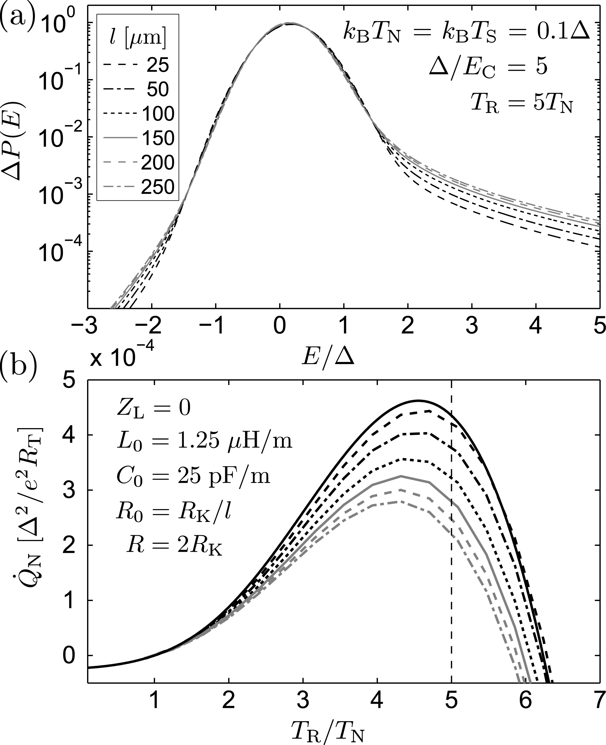
Figure 10: (a)a\left(\mathrm{a}\right)\;P(E)𝑃𝐸P(E) at TR=5TNsubscript𝑇R5subscript𝑇NT_{\mathrm{R}}=5T_{\mathrm{N}}, and (b)b\left(\mathrm{b}\right)\;cooling power Q˙Nsubscript˙𝑄N\dot{Q}_{\mathrm{N}} out of the N electrode for an NIS junction coupled to an RLC transmission line. The different curves correspond to the indicated values of the line length l𝑙l at the fixed inductance and capacitance per unit length C0subscript𝐶0C_{0}, and L0subscript𝐿0L_{0}. The solid black line shows Q˙Nsubscript˙𝑄N\dot{Q}_{\mathrm{N}} for a lumped RC environment with R=2RK𝑅2subscript𝑅KR=2R_{\mathrm{K}}.

To model an on-chip resistor taking also stray capacitance into account, we characterize it in terms of a resistance, capacitance, and inductance per unit length, denoted by R0subscript𝑅0R_{0}, C0subscript𝐶0C_{0}, and L0subscript𝐿0L_{0}, respectively. The top half of Fig. 8 (b)b\left(\mathrm{b}\right)\;sketches a distributed model of the NIS junction environment, and the bottom half shows the transformation to two standard two-port RLC transmission lines in series, each of length l𝑙l and terminated by an impedance ZL/2subscript𝑍L2Z_{\mathrm{L}}/2. For a single transmission line terminated by a load impedance ZL/2subscript𝑍L2Z_{\mathrm{L}}/2 at the position x=l𝑥𝑙x=l, the impedance at x=0𝑥0x=0 reads

Z(ω)=Z0e2iklλe2ikl+λ𝑍𝜔subscript𝑍0superscript𝑒2𝑖𝑘𝑙𝜆superscript𝑒2𝑖𝑘𝑙𝜆Z(\omega)=Z_{0}\frac{e^{2ikl}-\lambda}{e^{2ikl}+\lambda} (15)

with the wave number k=iωR0C0+ω2L0C0𝑘𝑖𝜔subscript𝑅0subscript𝐶0superscript𝜔2subscript𝐿0subscript𝐶0k=\sqrt{-i\omega R_{0}C_{0}+\omega^{2}L_{0}C_{0}}, the characteristic impedance Z0=(R0+iωL0)/(iωC0),subscript𝑍0subscript𝑅0𝑖𝜔subscript𝐿0𝑖𝜔subscript𝐶0Z_{0}=\sqrt{(R_{0}+i\omega L_{0})/(i\omega C_{0})}, and the reflection coefficient λ=(Z0ZL/2)/(Z0+ZL/2)𝜆subscript𝑍0subscript𝑍L2subscript𝑍0subscript𝑍L2\lambda=(Z_{0}-Z_{\mathrm{L}}/2)/(Z_{0}+Z_{\mathrm{L}}/2). Here, Z0subscript𝑍0Z_{0} gives the impedance of a semi-infinite transmission line. In Fig. 10 (a)a\left(\mathrm{a}\right)\;we plot P(E)𝑃𝐸P(E) at TR=5TNsubscript𝑇R5subscript𝑇NT_{\mathrm{R}}=5T_{\mathrm{N}} and in (b)b\left(\mathrm{b}\right)\;Q˙Nsubscript˙𝑄N\dot{Q}_{\mathrm{N}} as a function of TRsubscript𝑇RT_{\mathrm{R}} for a single NIS junction, assuming ZL=0subscript𝑍L0Z_{\mathrm{L}}=0. Each of the two transmission lines is described by a fixed L0=1.25μH/msubscript𝐿01.25𝜇HmL_{0}=1.25\;\mu\mathrm{H}/\mathrm{m} and C0=25pF/msubscript𝐶025pFmC_{0}=25\;\mathrm{pF}/\mathrm{m}, whereas R0=RK/lsubscript𝑅0subscript𝑅K𝑙R_{0}=R_{\mathrm{K}}/l is changing as l𝑙l varies from 25μm25𝜇m25\;\mu\mathrm{m} to 250μm250𝜇m250\;\mu\mathrm{m}. The values of L0subscript𝐿0L_{0} and C0subscript𝐶0C_{0} are feasible for a resistor consisting of a thin and narrow strip of a resistive metal or alloy. Figure 10 (b)b\left(\mathrm{b}\right)\;illustrates how the non-zero stray capacitance reduces the cooling power. On the other hand, the distributed inductance can be neglected, and the results are almost indistinguishable from those of an RC transmission line.

V.3 Lossless transmission line
Refer to caption
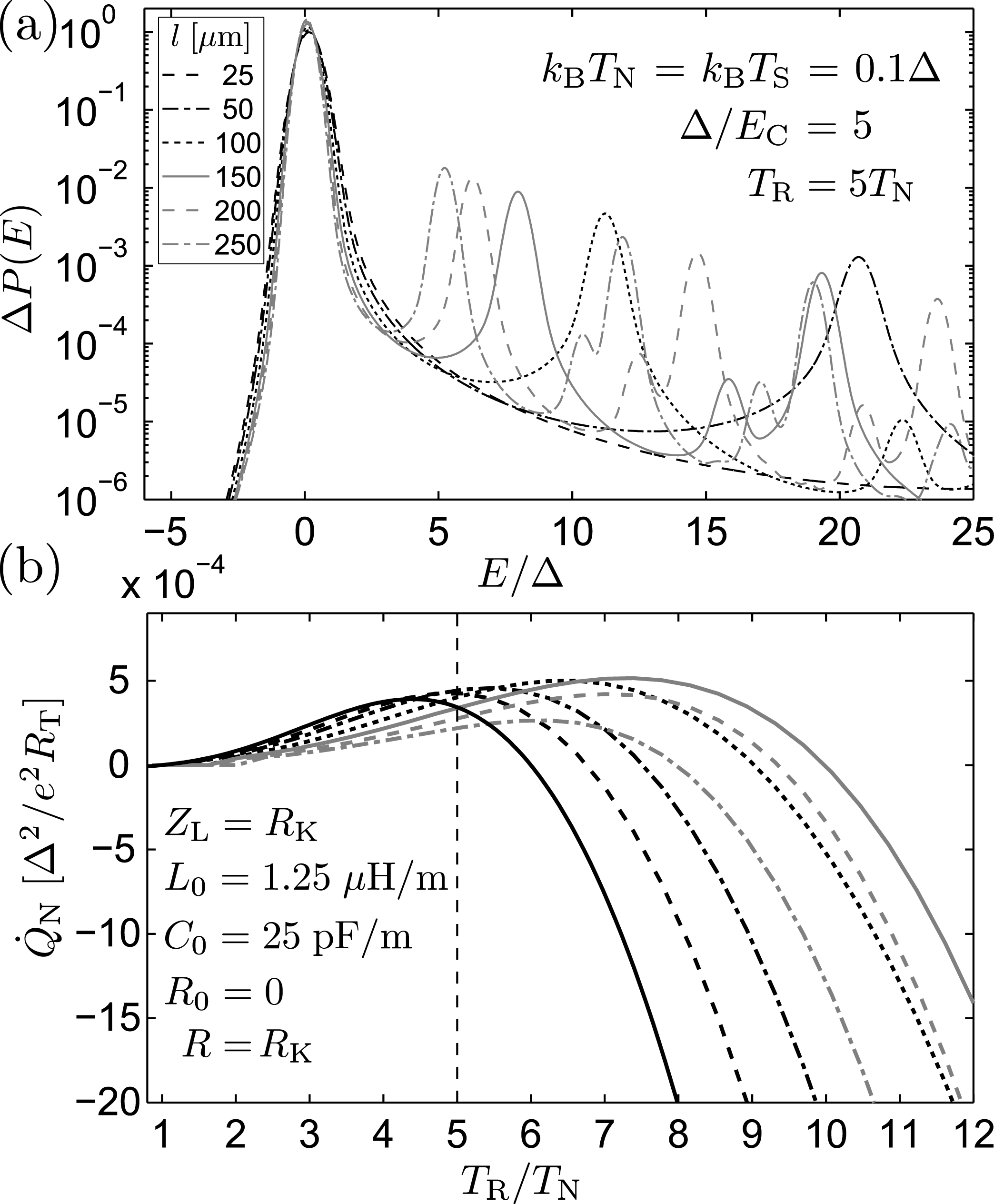
Figure 11: (a)a\left(\mathrm{a}\right)\;P(E)𝑃𝐸P(E) at TR=5TNsubscript𝑇R5subscript𝑇NT_{\mathrm{R}}=5T_{\mathrm{N}}, and (b)b\left(\mathrm{b}\right)\;cooling power Q˙Nsubscript˙𝑄N\dot{Q}_{\mathrm{N}} out of the N electrode for an NIS junction coupled to an LC transmission line terminated by a lumped resistor R𝑅R. The different curves correspond to the indicated values of the line length l𝑙l at the fixed inductance and capacitance per unit length C0subscript𝐶0C_{0}, and L0subscript𝐿0L_{0}. The thick black line shows Q˙Nsubscript˙𝑄N\dot{Q}_{\mathrm{N}} for a lumped RC environment.

Instead of distributing the resistance R𝑅R along the transmission line, here we calculate Q˙Nsubscript˙𝑄N\dot{Q}_{\mathrm{N}} for a lossless LC line with R0=0subscript𝑅00R_{0}=0 and ZL=RKsubscript𝑍Lsubscript𝑅KZ_{\mathrm{L}}=R_{\mathrm{K}}. Figure 11 (a)a\left(\mathrm{a}\right)\;shows P(E)𝑃𝐸P(E) at TR=5TNsubscript𝑇R5subscript𝑇NT_{\mathrm{R}}=5T_{\mathrm{N}} and (b)b\left(\mathrm{b}\right)\;Q˙Nsubscript˙𝑄N\dot{Q}_{\mathrm{N}} as a function of TRsubscript𝑇RT_{\mathrm{R}} for a single NIS junction. Again, each of the two transmission lines of length l𝑙l is described by a fixed L0=1.25μH/msubscript𝐿01.25𝜇HmL_{0}=1.25\;\mu\mathrm{H}/\mathrm{m} and C0=25pF/msubscript𝐶025pFmC_{0}=25\;\mathrm{pF}/\mathrm{m}, whereas now R0=0subscript𝑅00R_{0}=0. In contrast to the RLC transmission line in Sec. V.2, Q˙Nsubscript˙𝑄N\dot{Q}_{\mathrm{N}} is maximized at a certain length l𝑙l when the inductance filters the high frequency fluctuations but the stray capacitance does not yet shunt them. The side peaks at E>0𝐸0E>0 visible in P(E)𝑃𝐸P(E) occur around energies corresponding to the frequencies at which Re[Zt(ω)]Redelimited-[]subscript𝑍t𝜔\mathrm{Re}[Z_{\mathrm{t}}(\omega)] has a local maximum, and their sum frequencies.

VI Cooling by shot noise

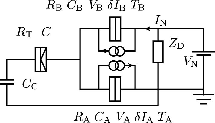
So far, the analysis has been limited to equilibrium fluctuations as the origin of the noise-induced cooling power out from the normal metal electrode. In this section we expand the treatment to include a special case of nonequilibrium fluctuations: We focus on the system consisting of an NIS junction coupled to the shot noise generated by another, on-chip, voltage biased tunnel junction. To be more specific, we analyze the circuit illustrated in Fig. 12, where the NIS junction is coupled capacitively (via on-chip coupling capacitor of capacitance CCsubscript𝐶CC_{\mathrm{C}}) to two sources of shot noise, tunnel junctions A and B. The former is again characterized by the tunnel resistance RTsubscript𝑅TR_{\mathrm{T}}, capacitance C𝐶C, and temperatures TNsubscript𝑇NT_{\mathrm{N}} and TSsubscript𝑇ST_{\mathrm{S}}, whereas the corresponding values for the latter two read RAsubscript𝑅AR_{\mathrm{A}} and RBsubscript𝑅BR_{\mathrm{B}}, CAsubscript𝐶AC_{\mathrm{A}} and CBsubscript𝐶BC_{\mathrm{B}}, and TAsubscript𝑇AT_{\mathrm{A}} and TBsubscript𝑇BT_{\mathrm{B}}, respectively. Junctions A and B in series are biased by a constant voltage VNsubscript𝑉NV_{\mathrm{N}}, producing an average current INsubscript𝐼NI_{\mathrm{N}} as well as the current fluctuations δIA𝛿subscript𝐼A\delta I_{\mathrm{A}} and δIB𝛿subscript𝐼B\delta I_{\mathrm{B}}. Voltages across individual junctions are denoted by VAsubscript𝑉AV_{\mathrm{A}} and VBsubscript𝑉BV_{\mathrm{B}}. The two noise source junctions are shunted by impedance ZDsubscript𝑍DZ_{\mathrm{D}}, e.g., a large capacitance CDsubscript𝐶DC_{\mathrm{D}}. In the following, either ZDsubscript𝑍DZ_{\mathrm{D}} or the voltage biasing circuit itself are assumed to act effectively as a short at the relevant frequencies. For most of the discussion to follow, we limit for simplicity to fully normal NIN junctions as the noise generators, although some of the results apply to any type of hybrid tunnel junctions.
Refer to caption
Figure 12: Circuit for studying shot noise-induced cooling in a hybrid tunnel junction: an NIS junction of resistance RTsubscript𝑅TR_{\mathrm{T}} and capacitance C𝐶C is coupled capacitively through CCsubscript𝐶CC_{\mathrm{C}} to two voltage biased NIN junctions A and B that generate shot noise. The noise is described by the current fluctuations δIi𝛿subscript𝐼𝑖\delta I_{i}, and the junction parameters include the resistance Risubscript𝑅𝑖R_{i}, capacitance Cisubscript𝐶𝑖C_{i}, bias voltage Visubscript𝑉𝑖V_{i}, and temperature Tisubscript𝑇𝑖T_{i} (i=A,B)𝑖AB(i=\mathrm{A},\mathrm{B}).

With nonequilibrium fluctuations present, the tunneling rates across the NIS junction can in general no longer be written in terms of a single function P(E)𝑃𝐸P(E) defined by Eq. (3). Instead, we find

Γ+=superscriptΓabsent\displaystyle\Gamma^{+}= 1e2RTdEdEni(E)nj(E+eV)×\displaystyle\frac{1}{e^{2}R_{\mathrm{T}}}\int_{-\infty}^{\infty}\int_{-\infty}^{\infty}dEdE^{\prime}n_{i}(E)n_{j}(E^{\prime}+eV)\times
fi(E)[1fj(E+eV)]P+(EE)subscript𝑓𝑖𝐸delimited-[]1subscript𝑓𝑗superscript𝐸𝑒𝑉superscript𝑃𝐸superscript𝐸\displaystyle f_{i}(E)\left[1-f_{j}(E^{\prime}+eV)\right]P^{+}(E-E^{\prime}) (16)

for the forward tunneling rate from electrode i𝑖i to j𝑗j. Analogously, the backward rate reads

Γ=superscriptΓabsent\displaystyle\Gamma^{-}= 1e2RTdEdEni(E)nj(E+eV)×\displaystyle\frac{1}{e^{2}R_{\mathrm{T}}}\int_{-\infty}^{\infty}\int_{-\infty}^{\infty}dEdE^{\prime}n_{i}(E)n_{j}(E^{\prime}+eV)\times
[1fi(E)]fj(E+eV)P(EE).delimited-[]1subscript𝑓𝑖𝐸subscript𝑓𝑗superscript𝐸𝑒𝑉superscript𝑃superscript𝐸𝐸\displaystyle\left[1-f_{i}(E)\right]f_{j}(E^{\prime}+eV)P^{-}(E^{\prime}-E). (17)

Here, the functions

P±(E)=12π𝑑teiEt/e±iφ(t)eiφ(0)superscript𝑃plus-or-minus𝐸12𝜋Planck-constant-over-2-pisuperscriptsubscriptdifferential-d𝑡superscript𝑒𝑖𝐸𝑡Planck-constant-over-2-pidelimited-⟨⟩superscript𝑒plus-or-minus𝑖𝜑𝑡superscript𝑒minus-or-plus𝑖𝜑0P^{\pm}(E)=\frac{1}{2\pi\hbar}\int_{-\infty}^{\infty}dte^{iEt/\hbar}\langle e^{\pm i\varphi(t)}e^{\mp i\varphi(0)}\rangle (18)

have a similar interpretation to the P(E)𝑃𝐸P(E) of Eq. (3) valid for an equilibrium environment of the NIS junction in terms of energy absorption and emission heikkila05 . However, for non-Gaussian noise, they are not necessarily equal to each other, and the statistical averaging over the environment is hard to perform. An extension of the P(E)𝑃𝐸P(E)-theory to a nonequilibrium environment with possibly nonzero higher cumulants is considered also in Ref. sukhorukov08, . In the following we limit to effects arising from the second cumulant of the shot noise, and set P±(E)=P(E)superscript𝑃plus-or-minus𝐸𝑃𝐸P^{\pm}(E)=P(E). This corresponds to performing a cumulant expansion of the quantities e±iφ(t)eiφ(0)delimited-⟨⟩superscript𝑒plus-or-minus𝑖𝜑𝑡superscript𝑒minus-or-plus𝑖𝜑0\langle e^{\pm i\varphi(t)}e^{\mp i\varphi(0)}\rangle and keeping only the first non-vanishing terms, which is justified if the expansion is converging quickly. Following Ref. heikkila05, and assuming the circuit cut-off frequency ωCsubscript𝜔C\omega_{\mathrm{C}} to be smaller than the intrinsic frequency scales of the cumulants, we can estimate that the requirement Reff/RK<1subscript𝑅effsubscript𝑅K1R_{\mathrm{eff}}/R_{\mathrm{K}}<1 should be satisfied for fast decay of the higher order terms. Here, Reffsubscript𝑅effR_{\mathrm{eff}} is the effective noise source resistance seen by the NIS junction. It depends on the intrinsic resistances RAsubscript𝑅AR_{\mathrm{A}} and RBsubscript𝑅BR_{\mathrm{B}} as well as the various capacitances in Fig. 12, as will be shown below.

Assuming weak effects from the higher order phase correlations, P(E)𝑃𝐸P(E) can be written as in Eqs. (3) and (4) in terms of the spectral density of the phase fluctuations across the junction, and the problem reduces to specifying this quantity in the presence of shot noise. We start by analyzing the circuit of Fig. 12 to arrive at a relation connecting the voltage fluctuation δV(ω)𝛿𝑉𝜔\delta V(\omega) across the NIS junction to the intrinsic current fluctuations δIA(ω)𝛿subscript𝐼A𝜔\delta I_{\mathrm{A}}(\omega) and δIB(ω)𝛿subscript𝐼B𝜔\delta I_{\mathrm{B}}(\omega) of the two source junctions. Assuming ZDsubscript𝑍DZ_{\mathrm{D}} to be negligibly small, we obtain δV(ω)=ZT(ω)[δIA(ω)δIB(ω)]𝛿𝑉𝜔subscript𝑍T𝜔delimited-[]𝛿subscript𝐼A𝜔𝛿subscript𝐼B𝜔\delta V(\omega)=Z_{\mathrm{T}}(\omega)\left[\delta I_{\mathrm{A}}(\omega)-\delta I_{\mathrm{B}}(\omega)\right] with the transimpedance ZT(ω)=Reff/(1iωReffCeff)subscript𝑍T𝜔subscript𝑅eff1𝑖𝜔subscript𝑅effsubscript𝐶effZ_{\mathrm{T}}(\omega)=R_{\mathrm{eff}}/(1-i\omega R_{\mathrm{eff}}C_{\mathrm{eff}}). Here, the effective resistance Reffsubscript𝑅effR_{\mathrm{eff}} and effective capacitance Ceffsubscript𝐶effC_{\mathrm{eff}} are related to parameters of the circuit elements by

Reffsubscript𝑅eff\displaystyle R_{\mathrm{eff}} =CCCC+CSRABwithRAB=RARBRA+RB,absentsubscript𝐶Csubscript𝐶Csubscript𝐶Ssubscript𝑅ABwithsubscript𝑅ABsubscript𝑅Asubscript𝑅Bsubscript𝑅Asubscript𝑅B\displaystyle=\frac{C_{\mathrm{C}}}{C_{\mathrm{C}}+C_{\mathrm{S}}}R_{\mathrm{AB}}\;\;\mathrm{with}\;\;R_{\mathrm{AB}}=\frac{R_{\mathrm{A}}R_{\mathrm{B}}}{R_{\mathrm{A}}+R_{\mathrm{B}}}, (19)
Ceffsubscript𝐶eff\displaystyle C_{\mathrm{eff}} =CA+CB+CA+CB+CCCCCS.absentsubscript𝐶Asubscript𝐶Bsubscript𝐶Asubscript𝐶Bsubscript𝐶Csubscript𝐶Csubscript𝐶S\displaystyle=C_{\mathrm{A}}+C_{\mathrm{B}}+\frac{C_{\mathrm{A}}+C_{\mathrm{B}}+C_{\mathrm{C}}}{C_{\mathrm{C}}}C_{\mathrm{S}}. (20)

For stationary and uncorrelated fluctuations δIA/B(ω)𝛿subscript𝐼AB𝜔\delta I_{\mathrm{A}/\mathrm{B}}(\omega), the spectral density SV(ω)subscript𝑆𝑉𝜔S_{V}(\omega) of voltage noise δV(ω)𝛿𝑉𝜔\delta V(\omega) at the NIS junction is then related to the spectral densities SI,A/B(ω)subscript𝑆𝐼AB𝜔S_{I,\mathrm{A}/\mathrm{B}}(\omega) of δIA/B(ω)𝛿subscript𝐼AB𝜔\delta I_{\mathrm{A}/\mathrm{B}}(\omega) via

SV(ω)=|ZT(ω)|2[SI,A(ω)+SI,B(ω)].subscript𝑆𝑉𝜔superscriptsubscript𝑍T𝜔2delimited-[]subscript𝑆𝐼A𝜔subscript𝑆𝐼B𝜔S_{V}(\omega)=\left|Z_{\mathrm{T}}(\omega)\right|^{2}\left[S_{I,\mathrm{A}}(\omega)+S_{I,\mathrm{B}}(\omega)\right]. (21)

Based on this relation, the phase noise spectral density directly is given by

Sφ(ω)=(e)21ω2|ZT(ω)|2[SI,A(ω)+SI,B(ω)].subscript𝑆𝜑𝜔superscript𝑒Planck-constant-over-2-pi21superscript𝜔2superscriptsubscript𝑍T𝜔2delimited-[]subscript𝑆𝐼A𝜔subscript𝑆𝐼B𝜔S_{\varphi}(\omega)=\left(\frac{e}{\hbar}\right)^{2}\frac{1}{\omega^{2}}\left|Z_{\mathrm{T}}(\omega)\right|^{2}\left[S_{I,\mathrm{A}}(\omega)+S_{I,\mathrm{B}}(\omega)\right]. (22)

The remaining task to obtain the correlation function J(t)𝐽𝑡J(t) from Eq. (4) and using it to calculate P(E)𝑃𝐸P(E) from Eq. (3) reduces hence to specifying the intrinsic current noise spectral densities SI,A/B(ω)subscript𝑆𝐼AB𝜔S_{I,\mathrm{A}/\mathrm{B}}(\omega) appearing in Eq. (22). For tunnel junction A one finds

SI,A(ω)=eIqpA(ω/e+VA)1exp(ω+eVAkBTA)+eIqpA(ω/eVA)1exp(ωeVAkBTA),subscript𝑆𝐼A𝜔𝑒superscriptsubscript𝐼qpAPlanck-constant-over-2-pi𝜔𝑒subscript𝑉A1Planck-constant-over-2-pi𝜔𝑒subscript𝑉Asubscript𝑘Bsubscript𝑇A𝑒superscriptsubscript𝐼qpAPlanck-constant-over-2-pi𝜔𝑒subscript𝑉A1Planck-constant-over-2-pi𝜔𝑒subscript𝑉Asubscript𝑘Bsubscript𝑇AS_{I,\mathrm{A}}(\omega)=\frac{eI_{\mathrm{qp}}^{\mathrm{A}}(\hbar\omega/e+V_{\mathrm{A}})}{1-\exp\left(-\frac{\hbar\omega+eV_{\mathrm{A}}}{k_{\mathrm{B}}T_{\mathrm{A}}}\right)}+\frac{eI_{\mathrm{qp}}^{\mathrm{A}}(\hbar\omega/e-V_{\mathrm{A}})}{1-\exp\left(-\frac{\hbar\omega-eV_{\mathrm{A}}}{k_{\mathrm{B}}T_{\mathrm{A}}}\right)}, (23)

where IqpA(VA)superscriptsubscript𝐼qpAsubscript𝑉AI_{\mathrm{qp}}^{\mathrm{A}}(V_{\mathrm{A}}) denotes the DC quasiparticle current through the junction at the bias voltage VAsubscript𝑉AV_{\mathrm{A}}, and TAsubscript𝑇AT_{\mathrm{A}} denotes its equilibrium temperature billangeon06 . A similar result holds for junction B. For NIN noise sources Eq. (23) is identical to an expression for SI,A(ω)subscript𝑆𝐼A𝜔S_{I,\mathrm{A}}(\omega) derived from a scattering matrix calculation aguado00 :

SI,A(ω)=ωRA[coth(βAω/2)+1]+FARA×\displaystyle S_{I,\mathrm{A}}(\omega)=\frac{\hbar\omega}{R_{\mathrm{A}}}\left[\coth\left(\beta_{\mathrm{A}}\hbar\omega/2\right)+1\right]+\frac{F_{\mathrm{A}}}{R_{\mathrm{A}}}\times (24)
eVAsinh(βAeVA)2ωcoth(βAω/2)sinh2(βAeVA/2)cosh(βAeVA)cosh(βAω),𝑒subscript𝑉Asubscript𝛽A𝑒subscript𝑉A2Planck-constant-over-2-pi𝜔hyperbolic-cotangentsubscript𝛽APlanck-constant-over-2-pi𝜔2superscript2subscript𝛽A𝑒subscript𝑉A2subscript𝛽A𝑒subscript𝑉Asubscript𝛽APlanck-constant-over-2-pi𝜔\displaystyle\frac{eV_{\mathrm{A}}\sinh\left(\beta_{\mathrm{A}}eV_{\mathrm{A}}\right)-2\hbar\omega\coth\left(\beta_{\mathrm{A}}\hbar\omega/2\right)\sinh^{2}\left(\beta_{\mathrm{A}}eV_{\mathrm{A}}/2\right)}{\cosh\left(\beta_{\mathrm{A}}eV_{\mathrm{A}}\right)-\cosh\left(\beta_{\mathrm{A}}\hbar\omega\right)},

with βA=1/kBTAsubscript𝛽A1subscript𝑘Bsubscript𝑇A\beta_{\mathrm{A}}=1/k_{\mathrm{B}}T_{\mathrm{A}}, and FAsubscript𝐹AF_{\mathrm{A}} denoting the (second order) Fano factor of the junction. Here we identify the two independent noise sources SI,A(ω)=SI,Aeq(ω)+SI,Ashot(ω)subscript𝑆𝐼A𝜔superscriptsubscript𝑆𝐼Aeq𝜔superscriptsubscript𝑆𝐼Ashot𝜔S_{I,\mathrm{A}}(\omega)=S_{I,\mathrm{A}}^{\mathrm{eq}}(\omega)+S_{I,\mathrm{A}}^{\mathrm{shot}}(\omega) where SI,Aeq(ω)=(ω/RA)[coth(βAω/2)+1]superscriptsubscript𝑆𝐼Aeq𝜔Planck-constant-over-2-pi𝜔subscript𝑅Adelimited-[]hyperbolic-cotangentsubscript𝛽APlanck-constant-over-2-pi𝜔21S_{I,\mathrm{A}}^{\mathrm{eq}}(\omega)=(\hbar\omega/R_{\mathrm{A}})\left[\coth\left(\beta_{\mathrm{A}}\hbar\omega/2\right)+1\right] is the equilibrium, i.e., zero bias contribution to the spectral density, and the shot noise part is defined as the second term in Eq. (24). It is worth noting that inserting the equilibrium current noise for a single resistor into Eq. (22) and using this phase spectral density to calculate J(t)𝐽𝑡J(t) from Eq. (4), one recovers the equilibrium result of Eq. (5). We define Sφ(ω)=Sφeq(ω)+Sφshot(ω)subscript𝑆𝜑𝜔superscriptsubscript𝑆𝜑eq𝜔superscriptsubscript𝑆𝜑shot𝜔S_{\varphi}(\omega)=S_{\varphi}^{\mathrm{eq}}(\omega)+S_{\varphi}^{\mathrm{shot}}(\omega) with

Sφeq/shot(ω)=(e)2|ZT(ω)|2ω2[SI,Aeq/shot(ω)+SI,Beq/shot(ω)].superscriptsubscript𝑆𝜑eqshot𝜔superscript𝑒Planck-constant-over-2-pi2superscriptsubscript𝑍T𝜔2superscript𝜔2delimited-[]superscriptsubscript𝑆𝐼Aeqshot𝜔superscriptsubscript𝑆𝐼Beqshot𝜔S_{\varphi}^{\mathrm{eq}/\mathrm{shot}}(\omega)=\left(\frac{e}{\hbar}\right)^{2}\frac{\left|Z_{\mathrm{T}}(\omega)\right|^{2}}{\omega^{2}}\left[S_{I,\mathrm{A}}^{\mathrm{eq}/\mathrm{shot}}(\omega)+S_{I,\mathrm{B}}^{\mathrm{eq}/\mathrm{shot}}(\omega)\right]. (25)

Similarly, J(t)=Jeq(t)+Jshot(t)𝐽𝑡superscript𝐽eq𝑡superscript𝐽shot𝑡J(t)=J^{\mathrm{eq}}(t)+J^{\mathrm{shot}}(t) with

Jeq/shot(t)=12π𝑑ωSφeq/shot(ω)[eiωt1].superscript𝐽eqshot𝑡12𝜋superscriptsubscriptdifferential-d𝜔superscriptsubscript𝑆𝜑eqshot𝜔delimited-[]superscript𝑒𝑖𝜔𝑡1J^{\mathrm{eq}/\mathrm{shot}}(t)=\frac{1}{2\pi}\int_{-\infty}^{\infty}d\omega S_{\varphi}^{\mathrm{eq}/\mathrm{shot}}(\omega)\left[e^{-i\omega t}-1\right]. (26)

Starting with Jeq(t)superscript𝐽eq𝑡J^{\mathrm{eq}}(t), we have explicitly

Jeq(t)=superscript𝐽eq𝑡absent\displaystyle J^{\mathrm{eq}}(t)= (ReffRA)JRC(t;Reff,Ceff,TA)+limit-fromsubscript𝑅effsubscript𝑅Asuperscript𝐽RC𝑡subscript𝑅effsubscript𝐶effsubscript𝑇A\displaystyle\left(\frac{R_{\mathrm{eff}}}{R_{\mathrm{A}}}\right)J^{\mathrm{RC}}(t\,;R_{\mathrm{eff}},C_{\mathrm{eff}},T_{\mathrm{A}})+
(ReffRB)JRC(t;Reff,Ceff,TB),subscript𝑅effsubscript𝑅Bsuperscript𝐽RC𝑡subscript𝑅effsubscript𝐶effsubscript𝑇B\displaystyle\left(\frac{R_{\mathrm{eff}}}{R_{\mathrm{B}}}\right)J^{\mathrm{RC}}(t\,;R_{\mathrm{eff}},C_{\mathrm{eff}},T_{\mathrm{B}}), (27)

where JRC(t;R,C,TR)superscript𝐽RC𝑡𝑅𝐶subscript𝑇RJ^{\mathrm{RC}}(t\,;R,C,T_{\mathrm{R}}) denotes the equilibrium J(t)𝐽𝑡J(t) of Eq. (5) for a resistance R𝑅R at temperature TRsubscript𝑇RT_{\mathrm{R}} in parallel with the junction capacitance C𝐶C. On the other hand, since SI,A/Bshot(ω)superscriptsubscript𝑆𝐼ABshot𝜔S_{I,\mathrm{A}/\mathrm{B}}^{\mathrm{shot}}(\omega) are symmetric in ω𝜔\omega, the shot noise contribution reads

Jshot(t)=superscript𝐽shot𝑡absent\displaystyle J^{\mathrm{shot}}(t)= 2RK0dω|ZT(ω)|2ω2[cosωt1]×\displaystyle\frac{2}{R_{\mathrm{K}}}\int_{0}^{\infty}d\omega\frac{|Z_{\mathrm{T}}(\omega)|^{2}}{\hbar\omega^{2}}\left[\cos\omega t-1\right]\times
[SI,Ashot(ω)+SI,Bshot(ω)].delimited-[]superscriptsubscript𝑆𝐼Ashot𝜔superscriptsubscript𝑆𝐼Bshot𝜔\displaystyle\left[S_{I,\mathrm{A}}^{\mathrm{shot}}(\omega)+S_{I,\mathrm{B}}^{\mathrm{shot}}(\omega)\right]. (28)

To proceed, we assume the conditions βA/B/(2ReffCeff)1much-less-thansubscript𝛽ABPlanck-constant-over-2-pi2subscript𝑅effsubscript𝐶eff1\beta_{\mathrm{A}/\mathrm{B}}\hbar/(2R_{\mathrm{eff}}C_{\mathrm{eff}})\ll 1 to hold, which is reasonable at typical experimental temperatures for typical values Reff10kΩgreater-than-or-equivalent-tosubscript𝑅eff10kΩR_{\mathrm{eff}}\gtrsim 10\;\mathrm{k}\Omega and Ceff1fFgreater-than-or-equivalent-tosubscript𝐶eff1fFC_{\mathrm{eff}}\gtrsim 1\;\mathrm{fF}. Then, SI,A/Bshot(ω)superscriptsubscript𝑆𝐼ABshot𝜔S_{I,\mathrm{A}/\mathrm{B}}^{\mathrm{shot}}(\omega) are essentially frequency-independent up to the circuit cut-off frequency ωC=1/(ReffCeff)subscript𝜔C1subscript𝑅effsubscript𝐶eff\omega_{\mathrm{C}}=1/(R_{\mathrm{eff}}C_{\mathrm{eff}}), and we approximate

Jshot(t)2RKSI,Ashot(0)+SI,Bshot(0)×\displaystyle J^{\mathrm{shot}}(t)\simeq\frac{2}{R_{\mathrm{K}}}\frac{S_{I,\mathrm{A}}^{\mathrm{shot}}(0)+S_{I,\mathrm{B}}^{\mathrm{shot}}(0)}{\hbar}\times
0𝑑ω|ZT(ω)|2ω2[cosωt1]superscriptsubscript0differential-d𝜔superscriptsubscript𝑍T𝜔2superscript𝜔2delimited-[]𝜔𝑡1\displaystyle\int_{0}^{\infty}d\omega\frac{|Z_{\mathrm{T}}(\omega)|^{2}}{\omega^{2}}\left[\cos\omega t-1\right] (29)
=ρ2Reff2Ceff[SI,Ashot(0)+SI,Bshot(0)](1|τ|e|τ|).absent𝜌2superscriptsubscript𝑅eff2subscript𝐶effPlanck-constant-over-2-pidelimited-[]superscriptsubscript𝑆𝐼Ashot0superscriptsubscript𝑆𝐼Bshot01𝜏superscript𝑒𝜏\displaystyle=\frac{\rho}{2}\frac{R_{\mathrm{eff}}^{2}C_{\mathrm{eff}}}{\hbar}\left[S_{I,\mathrm{A}}^{\mathrm{shot}}(0)+S_{I,\mathrm{B}}^{\mathrm{shot}}(0)\right]\left(1-|\tau|-e^{-|\tau|}\right).

Here, ρ=2πReff/RK𝜌2𝜋subscript𝑅effsubscript𝑅K\rho=2\pi R_{\mathrm{eff}}/R_{\mathrm{K}} and τ=t/(ReffCeff)𝜏𝑡subscript𝑅effsubscript𝐶eff\tau=t/(R_{\mathrm{eff}}C_{\mathrm{eff}}). Assuming further that βA/BeVA/B1much-greater-thansubscript𝛽AB𝑒subscript𝑉AB1\beta_{\mathrm{A}/\mathrm{B}}eV_{\mathrm{A}/\mathrm{B}}\gg 1, we recover the usual result SI,A/Bshot(0)eFA/BINsimilar-to-or-equalssuperscriptsubscript𝑆𝐼ABshot0𝑒subscript𝐹ABsubscript𝐼NS_{I,\mathrm{A}/\mathrm{B}}^{\mathrm{shot}}(0)\simeq eF_{\mathrm{A}/\mathrm{B}}I_{\mathrm{N}} with IN=VA/RA=VB/RBsubscript𝐼Nsubscript𝑉Asubscript𝑅Asubscript𝑉Bsubscript𝑅BI_{\mathrm{N}}=V_{\mathrm{A}}/R_{\mathrm{A}}=V_{\mathrm{B}}/R_{\mathrm{B}}.

Refer to caption
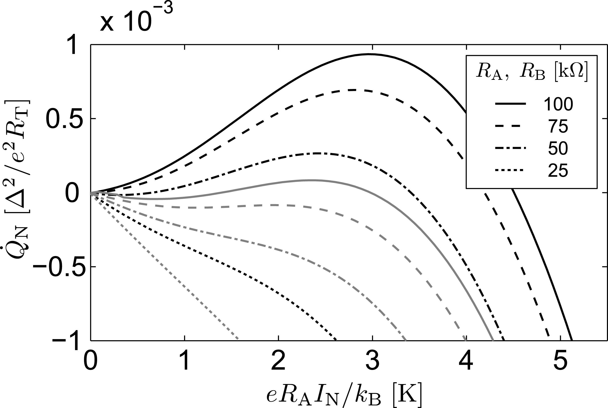
Figure 13: Examples of the shot noise-induced cooling power Q˙Nsubscript˙𝑄N\dot{Q}_{\mathrm{N}} for various noise source resistances RA=RBsubscript𝑅Asubscript𝑅BR_{\mathrm{A}}=R_{\mathrm{B}}, as a function of the average current INsubscript𝐼NI_{\mathrm{N}}. Black curves correspond to kBT=0.12Δsubscript𝑘B𝑇0.12Δk_{\mathrm{B}}T=0.12\Delta, and gray ones to kBT=0.1Δsubscript𝑘B𝑇0.1Δk_{\mathrm{B}}T=0.1\Delta Other parameters were kept fixed at C=2fF𝐶2fFC=2\;\mathrm{fF}, CA=CB=0.5fFsubscript𝐶Asubscript𝐶B0.5fFC_{\mathrm{A}}=C_{\mathrm{B}}=0.5\;\mathrm{fF}, and CC=10fFsubscript𝐶C10fFC_{\mathrm{C}}=10\;\mathrm{fF}.

Under these conditions at long times |τ|1much-greater-than𝜏1|\tau|\gg 1, the behavior of J(t)𝐽𝑡J(t) approaches

J(τ)=ρ|τ|ReffCeff[(ReffRA)kBTA\displaystyle J_{\infty}(\tau)=-\rho|\tau|\frac{R_{\mathrm{eff}}C_{\mathrm{eff}}}{\hbar}\left[\left(\frac{R_{\mathrm{eff}}}{R_{\mathrm{A}}}\right)k_{\mathrm{B}}T_{\mathrm{A}}\right.
+(ReffRB)kBTB+12ReffeIN(FA+FB)].\displaystyle\left.+\left(\frac{R_{\mathrm{eff}}}{R_{\mathrm{B}}}\right)k_{\mathrm{B}}T_{\mathrm{B}}+\frac{1}{2}R_{\mathrm{eff}}eI_{\mathrm{N}}(F_{\mathrm{A}}+F_{\mathrm{B}})\right]. (30)

Comparing to the equilibrium value ρ|τ|ReffCeffkBTeff/𝜌𝜏subscript𝑅effsubscript𝐶effsubscript𝑘Bsubscript𝑇effPlanck-constant-over-2-pi-\rho|\tau|R_{\mathrm{eff}}C_{\mathrm{eff}}k_{\mathrm{B}}T_{\mathrm{eff}}/\hbar for an RC𝑅𝐶RC environment formed by Ceffsubscript𝐶effC_{\mathrm{eff}} and Reffsubscript𝑅effR_{\mathrm{eff}} at a temperature Teffsubscript𝑇effT_{\mathrm{eff}}, we can define an effective temperature Teffsubscript𝑇effT_{\mathrm{eff}} via delahaye02

Teff=ReffeIN(FA+FB)2kB+(ReffRA)TA+(ReffRB)TB.subscript𝑇effsubscript𝑅eff𝑒subscript𝐼Nsubscript𝐹Asubscript𝐹B2subscript𝑘Bsubscript𝑅effsubscript𝑅Asubscript𝑇Asubscript𝑅effsubscript𝑅Bsubscript𝑇BT_{\mathrm{eff}}=\frac{R_{\mathrm{eff}}eI_{\mathrm{N}}(F_{\mathrm{A}}+F_{\mathrm{B}})}{2k_{\mathrm{B}}}+\left(\frac{R_{\mathrm{eff}}}{R_{\mathrm{A}}}\right)T_{\mathrm{A}}+\left(\frac{R_{\mathrm{eff}}}{R_{\mathrm{B}}}\right)T_{\mathrm{B}}. (31)

It is noteworthy that reaching Teff1Kgreater-than-or-equivalent-tosubscript𝑇eff1KT_{\mathrm{eff}}\gtrsim 1\;\mathrm{K} requires only 110pW110pW1-10\;\mathrm{pW} for RAsubscript𝑅AR_{\mathrm{A}} and RBsubscript𝑅BR_{\mathrm{B}} in the range of tens of kΩkΩ\mathrm{k}\Omegas, instead of 0.11nW0.11nW0.1-1\;\mathrm{nW} often needed to heat up an on-chip thin film resistor. To illustrate the cooling effect in the presence of shot noise, Fig. 13 plots Q˙Nsubscript˙𝑄N\dot{Q}_{\mathrm{N}} as a function of the average current INsubscript𝐼NI_{\mathrm{N}} through the NIN noise sources. For simplicity, we assume TN=TS=TA=TB=Tsubscript𝑇Nsubscript𝑇Ssubscript𝑇Asubscript𝑇B𝑇T_{\mathrm{N}}=T_{\mathrm{S}}=T_{\mathrm{A}}=T_{\mathrm{B}}=T. The different curves correspond to different resistances RA=RBsubscript𝑅Asubscript𝑅BR_{\mathrm{A}}=R_{\mathrm{B}}, whereas the other circuit parameters were fixed to the shown values. The result is qualitatively similar to cooling induced by thermal fluctuations, but TRsubscript𝑇RT_{\mathrm{R}} is replaced by INsubscript𝐼NI_{\mathrm{N}}.

VII Considerations for an experimental observation

VII.1 Coupling of the NIS junction and the resistor
Refer to caption
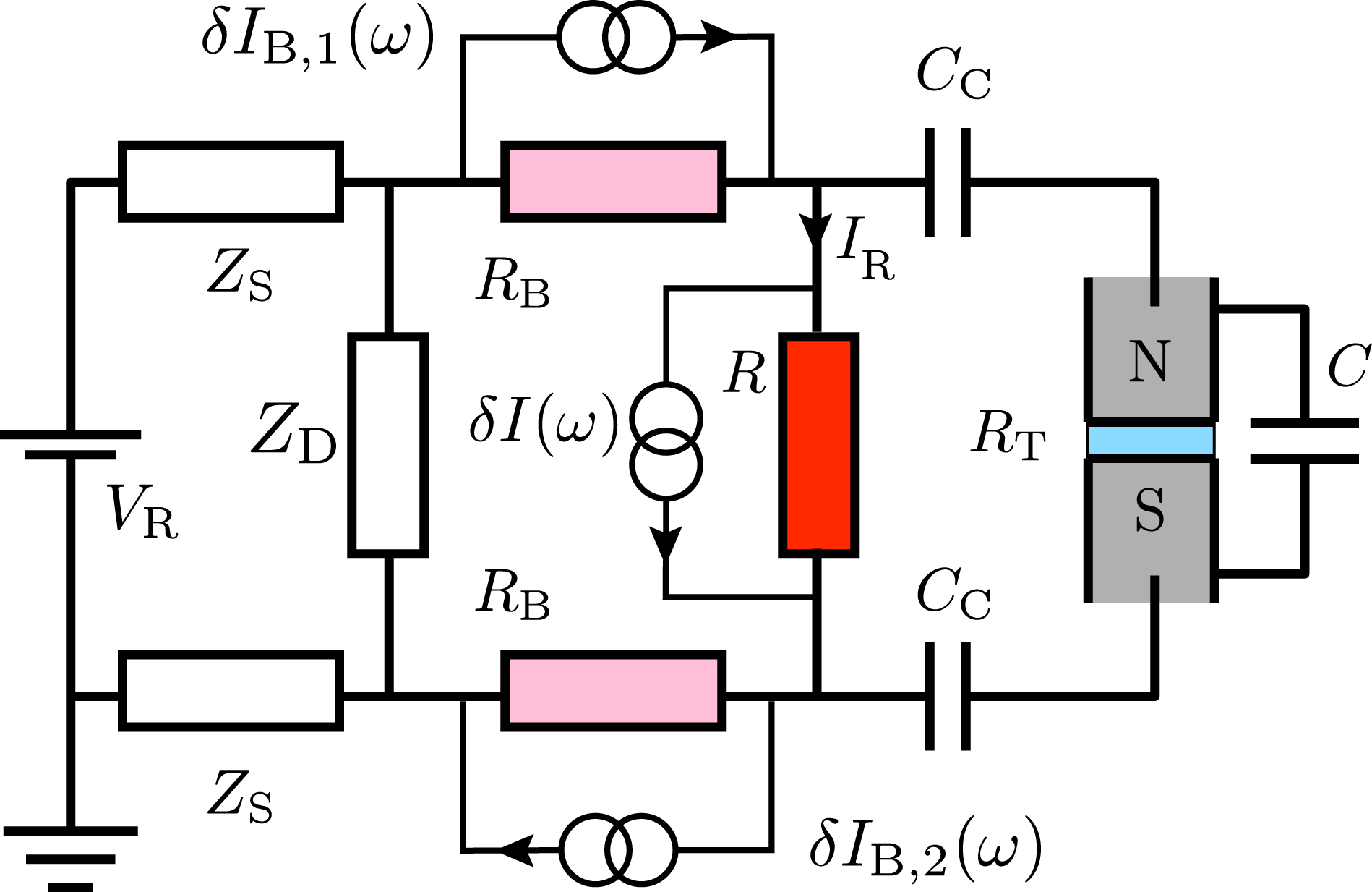
Figure 14: (color online) Practical coupling scheme for the noise-generating resistor of resistance R𝑅R and the NIS junction of capacitance C𝐶C and tunneling resistance RTsubscript𝑅TR_{\mathrm{T}}. See the text for details.

In an experimental realization of the hot resistor coupled to an NIS junction, an average heating current IRsubscript𝐼RI_{\mathrm{R}} is passed through the resistor with the help of a biasing circuit. The resistor is connected to external leads, and in addition, one must prevent the average current IRsubscript𝐼RI_{\mathrm{R}} from flowing through the NIS junction. Instead of the schematic in Fig. 1 (b)b\left(\mathrm{b}\right), here we take the circuit in Fig. 14 as a more realistic starting point. Current fluctuations δI(ω)𝛿𝐼𝜔\delta I(\omega) generated in the resistor are transformed into voltage fluctuations in the circuit, and coupled capacitively via capacitors CCsubscript𝐶CC_{\mathrm{C}} to the junction, whereas the average current IRsubscript𝐼RI_{\mathrm{R}} is blocked. The resistances RBRless-than-or-similar-tosubscript𝑅B𝑅R_{\mathrm{B}}\lesssim R in the bias leads should be located on-chip close to the resistor R𝑅R, to prevent most of the fluctuations δI(ω)𝛿𝐼𝜔\delta I(\omega) from being shunted in the external biasing circuit. In Fig. 14 this circuit is represented by the series lead impedances ZSsubscript𝑍SZ_{\mathrm{S}} and the shunting impedance ZDsubscript𝑍DZ_{\mathrm{D}}, the latter of which can consist of a purposely fabricated capacitor CDsubscript𝐶DC_{\mathrm{D}}. In the following we assume either ZSsubscript𝑍SZ_{\mathrm{S}} or ZDsubscript𝑍DZ_{\mathrm{D}} to act as a short at the frequencies of interest, so that looking from the resistor R𝑅R, the bias circuit appears as a resistance 2RB2subscript𝑅B2R_{\mathrm{B}}. Such high impedance bias leads with good shunting are important to create a well-defined electrical environment for the junction, formed ideally only by on-chip circuit elements deblock03 ; billangeon06 ; billangeon07 . Propagation of the current fluctuations δI(ω)𝛿𝐼𝜔\delta I(\omega) and δIB(ω)𝛿subscript𝐼B𝜔\delta I_{\mathrm{B}}(\omega) to voltage fluctuations δV(ω)𝛿𝑉𝜔\delta V(\omega) across the junction in an arbitrary circuit can be described systematically in terms of Langevin equations, in a manner similar to Ref. heikkila05, . The approach is valid at frequencies ω𝜔\omega low enough for the corresponding wavelengths to exceed the typical circuit dimensions. Analogously to Sec. VI, we obtain

SV(ω)=Reff21+(ωReffC)2[SI(ω)+SIB,1(ω)4+SIB,2(ω)4].subscript𝑆𝑉𝜔superscriptsubscript𝑅eff21superscript𝜔subscript𝑅eff𝐶2delimited-[]subscript𝑆𝐼𝜔subscript𝑆subscript𝐼B1𝜔4subscript𝑆subscript𝐼B2𝜔4S_{V}(\omega)=\frac{R_{\mathrm{eff}}^{2}}{1+(\omega R_{\mathrm{eff}}C)^{2}}\left[S_{I}(\omega)+\frac{S_{I_{\mathrm{B},1}}(\omega)}{4}+\frac{S_{I_{\mathrm{B},2}}(\omega)}{4}\right]. (32)

Here, the effective resistance Reffsubscript𝑅effR_{\mathrm{eff}} is given by Reff=RCC/(CC+2C)subscript𝑅effsubscript𝑅parallel-tosubscript𝐶Csubscript𝐶C2𝐶R_{\mathrm{eff}}=R_{\parallel}C_{\mathrm{C}}/(C_{\mathrm{C}}+2C) with R1=R1+(2RB)1superscriptsubscript𝑅parallel-to1superscript𝑅1superscript2subscript𝑅B1R_{\parallel}^{-1}=R^{-1}+(2R_{\mathrm{B}})^{-1}. Remarkably, assuming the equilibrium noise SI(ω)=(ω/R)[coth(βRω/2)+1]subscript𝑆𝐼𝜔Planck-constant-over-2-pi𝜔𝑅delimited-[]hyperbolic-cotangentsubscript𝛽RPlanck-constant-over-2-pi𝜔21S_{I}(\omega)=(\hbar\omega/R)[\coth(\beta_{\mathrm{R}}\hbar\omega/2)+1] and neglecting SIB(ω)subscript𝑆subscript𝐼B𝜔S_{I_{\mathrm{B}}}(\omega), we can still employ the simple model of an RC environment, provided we replace R𝑅R by Reffsubscript𝑅effR_{\mathrm{eff}} and scale J(t)𝐽𝑡J(t) by Reff/Rsubscript𝑅eff𝑅R_{\mathrm{eff}}/R. On the other hand, if RB=Rsubscript𝑅B𝑅R_{\mathrm{B}}=R and all the resistors are at the same temperature, also in this case R𝑅R can simply be replaced by Reffsubscript𝑅effR_{\mathrm{eff}} and J(t)𝐽𝑡J(t) scaled by 3Reff/2R3subscript𝑅eff2𝑅3R_{\mathrm{eff}}/2R. Finally, in the limit of CCCmuch-greater-thansubscript𝐶C𝐶C_{\mathrm{C}}\gg C and RBRmuch-greater-thansubscript𝑅B𝑅R_{\mathrm{B}}\gg R, we have ReffRsubscript𝑅eff𝑅R_{\mathrm{eff}}\rightarrow R, and an RC environment is again recovered.

VII.2 Absorption of photons by the N electrode

If the resistance RNsubscript𝑅NR_{\mathrm{N}} of the N electrode to be refrigerated is not negligibly small, there is an additional, counteracting heat flow. This direct photonic heat flow Pphsubscript𝑃phP_{\mathrm{ph}} from the hot resistor towards the colder N island via the junction capacitance diminishes the observable temperature reduction from the cooling power Q˙Nsubscript˙𝑄N\dot{Q}_{\mathrm{N}}. Assuming the resistor R𝑅R at TRsubscript𝑇RT_{\mathrm{R}} to be coupled to the N island (resistance RNsubscript𝑅NR_{\mathrm{N}}, temperature TNsubscript𝑇NT_{\mathrm{N}}) via a reactive impedance ZC(ω)subscript𝑍C𝜔Z_{\mathrm{C}}(\omega), the photonic power reads schmidt04 ; meschke06 ; pascal10

Pph=0dω2πω𝒯(ω)[n~R(ω)n~N(ω)].subscript𝑃phsuperscriptsubscript0𝑑𝜔2𝜋Planck-constant-over-2-pi𝜔𝒯𝜔delimited-[]subscript~𝑛R𝜔subscript~𝑛N𝜔P_{\mathrm{ph}}=\int_{0}^{\infty}\frac{d\omega}{2\pi}\hbar\omega\mathcal{T}(\omega)\left[\tilde{n}_{\mathrm{R}}(\omega)-\tilde{n}_{\mathrm{N}}(\omega)\right]. (33)

Here, 𝒯(ω)=4RRN/|R+RN+ZC(ω)|2𝒯𝜔4𝑅subscript𝑅Nsuperscript𝑅subscript𝑅Nsubscript𝑍C𝜔2\mathcal{T}(\omega)=4RR_{\mathrm{N}}/|R+R_{\mathrm{N}}+Z_{\mathrm{C}}(\omega)|^{2} can be viewed as a transmission coefficient for photons, whereas n~i(ω)=1/[exp(βiω)1],i=(R,N)formulae-sequencesubscript~𝑛𝑖𝜔1delimited-[]subscript𝛽𝑖Planck-constant-over-2-pi𝜔1𝑖RN\tilde{n}_{i}(\omega)=1/\left[\exp(\beta_{i}\hbar\omega)-1\right],\;i=(\mathrm{R},\mathrm{N}) denote Bose occupation factors of the two resistors. For direct coupling [ZC(ω)0]delimited-[]subscript𝑍C𝜔0[Z_{\mathrm{C}}(\omega)\equiv 0], integration of Eq. (33) yields

Pph0=4RRN(R+RN)2kB2ππ26TR+TN2(TRTN),superscriptsubscript𝑃ph04𝑅subscript𝑅Nsuperscript𝑅subscript𝑅N2superscriptsubscript𝑘B2𝜋Planck-constant-over-2-pisuperscript𝜋26subscript𝑇Rsubscript𝑇N2subscript𝑇Rsubscript𝑇NP_{\mathrm{ph}}^{0}=\frac{4RR_{\mathrm{N}}}{(R+R_{\mathrm{N}})^{2}}\frac{k_{\mathrm{B}}^{2}}{\pi\hbar}\frac{\pi^{2}}{6}\frac{T_{\mathrm{R}}+T_{\mathrm{N}}}{2}(T_{\mathrm{R}}-T_{\mathrm{N}}), (34)

demonstrating the quantized photon heat conductance meschke06 . To analyze photon absorption by RNsubscript𝑅NR_{\mathrm{N}} in the Brownian refrigeration scheme, we assume capacitive coupling [ZC(ω)=1/(iωCCph)]delimited-[]subscript𝑍C𝜔1𝑖𝜔superscriptsubscript𝐶Cph[Z_{\mathrm{C}}(\omega)=1/(i\omega C_{\mathrm{C}}^{\mathrm{ph}})] with the effective coupling capacitance CCphsuperscriptsubscript𝐶CphC_{\mathrm{C}}^{\mathrm{ph}} arising from the junction and stray capacitances. In Fig. 15 we compare the cooling power Q˙Nsubscript˙𝑄N\dot{Q}_{\mathrm{N}} and power Pphsubscript𝑃phP_{\mathrm{ph}} by which the island is heated due to the finite resistance RNsubscript𝑅NR_{\mathrm{N}}. Assuming realistic experimental values R=RK𝑅subscript𝑅KR=R_{\mathrm{K}}, RN=5Ωsubscript𝑅N5ΩR_{\mathrm{N}}=5\;\Omega, RT=20kΩsubscript𝑅T20kΩR_{\mathrm{T}}=20\;\mathrm{k}\Omega, Δ/EC=5Δsubscript𝐸C5\Delta/E_{\mathrm{C}}=5 (C2fF)C\simeq 2\;\mathrm{fF}), Δ=200μeVΔ200𝜇eV\Delta=200\;\mu\mathrm{eV}, and TN=TS=0.1Δsubscript𝑇Nsubscript𝑇S0.1ΔT_{\mathrm{N}}=T_{\mathrm{S}}=0.1\;\Delta, the curves from bottom to top correspond to values of CCphsuperscriptsubscript𝐶CphC_{\mathrm{C}}^{\mathrm{ph}} between 1fF1fF1\;\mathrm{fF} and 100fF100fF100\;\mathrm{fF}. For the majority of temperatures TRsubscript𝑇RT_{\mathrm{R}} contained in Fig. 15, Eq. (33) yield values very close to Pph0superscriptsubscript𝑃ph0P_{\mathrm{ph}}^{0}. We can conclude that the photonic heat flow constitutes a sizable effect that cannot be neglected in a wide range of TRsubscript𝑇RT_{\mathrm{R}}. A large mismatch between the resistances RNsubscript𝑅NR_{\mathrm{N}} and R𝑅R is essential for diminishing this heat flow compared to Q˙Nsubscript˙𝑄N\dot{Q}_{\mathrm{N}} arising from the environment-assisted quasiparticle tunneling.
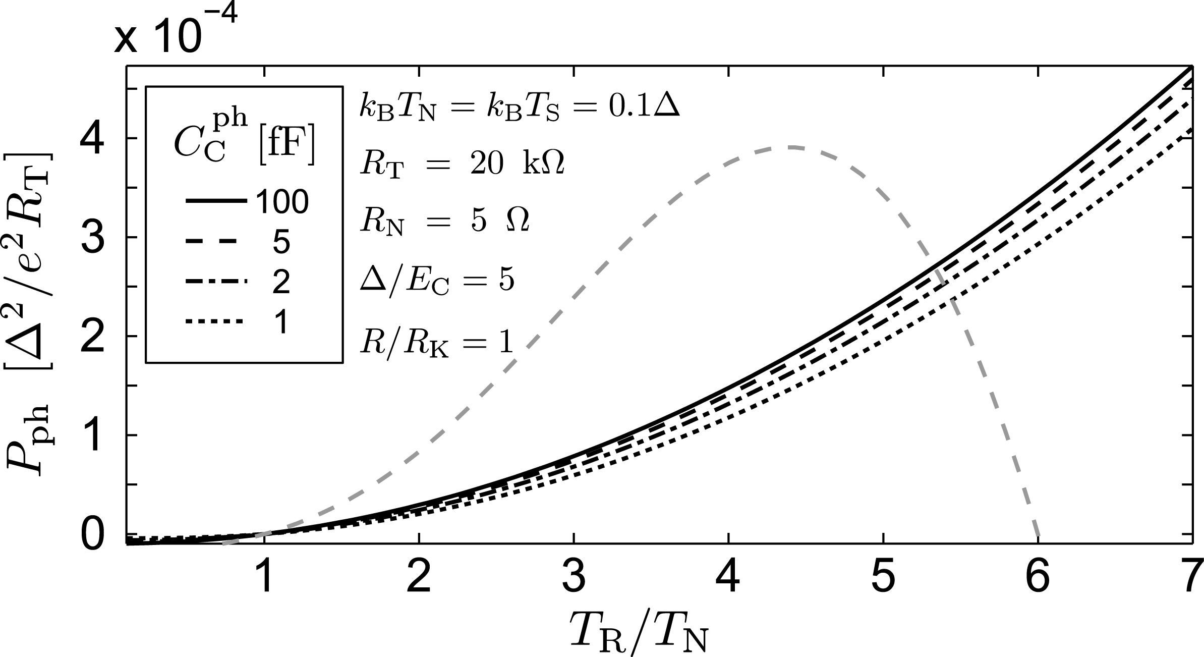
Refer to caption
Figure 15: Photon absorption power Pphsubscript𝑃phP_{\mathrm{ph}} due to a finite RNsubscript𝑅NR_{\mathrm{N}} compared to the cooling power Q˙Nsubscript˙𝑄N\dot{Q}_{\mathrm{N}} (gray dashed line). The curves from bottom to top were calculated with the indicated values of CCphsuperscriptsubscript𝐶CphC_{\mathrm{C}}^{\mathrm{ph}} ranging from 1fF1fF1\;\mathrm{fF} to 100fF100fF100\;\mathrm{fF}, whereas other parameters were fixed to the shown values.

VII.3 Heat balance

Refer to caption
Figure 16: (color online) Heat balance of the Brownian NIS refrigerator (a)a\left(\mathrm{a}\right), (b)b\left(\mathrm{b}\right)\;Contour plot of the temperature TNsubscript𝑇NT_{\mathrm{N}} of the N island as a function of the environment (resistor) and bath temperatures TRsubscript𝑇RT_{\mathrm{R}} and T0subscript𝑇0T_{0}, obtained as a solution of the steady state heat balance equation of the N island, Eq. (36). The temperatures are normalized by or compared to TN,0subscript𝑇N0T_{\mathrm{N},0}, defined as TNsubscript𝑇NT_{\mathrm{N}} at TR=T0subscript𝑇Rsubscript𝑇0T_{\mathrm{R}}=T_{0}. The calculation assumes Δ=200μeVΔ200𝜇eV\Delta=200\;\mu\mathrm{eV}, R=RK𝑅subscript𝑅KR=R_{\mathrm{K}}, Δ/EC=5Δsubscript𝐸C5\Delta/E_{\mathrm{C}}=5, RT=20kΩsubscript𝑅T20kΩR_{\mathrm{T}}=20\;\mathrm{k}\Omega, ΩN=2×10²¹m3subscriptΩN2superscript1021superscriptm3\Omega_{\mathrm{N}}=2\times 10^{-21}\;\mathrm{m}^{3}, ΣN=2×10⁹WK5m3subscriptΣN2superscript109superscriptWK5superscriptm3\Sigma_{\mathrm{N}}=2\times 10^{9}\;\mathrm{W}\mathrm{K}^{-5}\mathrm{m}^{-3}, and RN=5Ωsubscript𝑅N5ΩR_{\mathrm{N}}=5\;\Omega. In addition, we assume bias resistors with RB=Rsubscript𝑅B𝑅R_{\mathrm{B}}=R, and that all the three resistors are heated uniformly to TRsubscript𝑇RT_{\mathrm{R}}. The coupling capacitance CCsubscript𝐶CC_{\mathrm{C}} is set to 100C100𝐶100C, and we include the constant parasitic heating P0=1fWsubscript𝑃01fWP_{0}=1\;\mathrm{fW}, the cooling power Q˙thermsubscript˙𝑄therm\dot{Q}_{\mathrm{therm}} of an NIS junction thermometer of resistance RT,therm=20RTsubscript𝑅Ttherm20subscript𝑅TR_{\mathrm{T,therm}}=20R_{\mathrm{T}} biased at eV=0.6Δ𝑒𝑉0.6ΔeV=0.6\Delta [Eq. (1) with P(E)=δ(E)𝑃𝐸𝛿𝐸P(E)=\delta(E)], and finally the N island photon absorption Pphsubscript𝑃phP_{\mathrm{ph}} from Reffsubscript𝑅effR_{\mathrm{eff}} via an effective capacitance CCph=2fFsuperscriptsubscript𝐶Cph2fFC_{\mathrm{C}}^{\mathrm{ph}}=2\;\mathrm{fF}. The value of TRsubscript𝑇RT_{\mathrm{R}} at each T0subscript𝑇0T_{0} that results in the minimum TNsubscript𝑇NT_{\mathrm{N}} is indicated by the thick black line, while the black dot shows the point of optimum TRsubscript𝑇RT_{\mathrm{R}} and T0subscript𝑇0T_{0}. (c)c\left(\mathrm{c}\right)\;Influence of various parameters on the minimum temperature of the island as a function of T0subscript𝑇0T_{0}. The reference curve corresponds to the optimum line in (a)a\left(\mathrm{a}\right).

In this section we consider how to observe the cooling power Q˙Nsubscript˙𝑄N\dot{Q}_{\mathrm{N}}. In a typical on-chip configuration with a low temperature superconductor such as aluminum or titanium with Δ1meVmuch-less-thanΔ1meV\Delta\ll 1\;\mathrm{meV}, and small NIS tunnel junctions with C1fFsimilar-to-or-equals𝐶1fFC\simeq 1\;\mathrm{fF} and RT10kΩgreater-than-or-equivalent-tosubscript𝑅T10kΩR_{\mathrm{T}}\gtrsim 10\;\mathrm{k}\Omega, the magnitude of Q˙Nsubscript˙𝑄N\dot{Q}_{\mathrm{N}} becomes evident by writing the prefactor Δ2/(e2RT)superscriptΔ2superscript𝑒2subscript𝑅T\Delta^{2}/(e^{2}R_{\mathrm{T}}) in the form (Δ/100μeV)2/(RT/10kΩ)×1pWsuperscriptΔ100𝜇eV2subscript𝑅T10kΩ1pW(\Delta/100\;\mu\mathrm{eV})^{2}/(R_{\mathrm{T}}/10\;\mathrm{k}\Omega)\times 1\;\mathrm{pW}. Similarly, we can write Δ/EC(Δ/μeV)×(C/fF)/80similar-to-or-equalsΔsubscript𝐸CΔ𝜇eV𝐶fF80\Delta/E_{\mathrm{C}}\simeq(\Delta/\mu\mathrm{eV})\times(C/\mathrm{fF})/80. The heat flow Q˙Nsubscript˙𝑄N\dot{Q}_{\mathrm{N}} can be detected as a change in the electronic temperature TNsubscript𝑇NT_{\mathrm{N}} of an N electrode of finite size. To calculate the change in TNsubscript𝑇NT_{\mathrm{N}} due to Q˙Nsubscript˙𝑄N\dot{Q}_{\mathrm{N}}, we analyze the steady state heat balance equations

PextΣRΩR(TR5T05)+Q˙S+Q˙NPph=0andsubscript𝑃extsubscriptΣRsubscriptΩRsuperscriptsubscript𝑇R5superscriptsubscript𝑇05subscript˙𝑄Ssubscript˙𝑄Nsubscript𝑃ph0and\displaystyle P_{\mathrm{ext}}-\Sigma_{\mathrm{R}}\Omega_{\mathrm{R}}(T_{\mathrm{R}}^{5}-T_{0}^{5})+\dot{Q}_{\mathrm{S}}+\dot{Q}_{\mathrm{N}}-P_{\mathrm{ph}}=0\;\mathrm{and} (35)
ΣNΩN(T05TN5)Q˙NQ˙therm+P0+Pph=0,subscriptΣNsubscriptΩNsuperscriptsubscript𝑇05superscriptsubscript𝑇N5subscript˙𝑄Nsubscript˙𝑄thermsubscript𝑃0subscript𝑃ph0\displaystyle\Sigma_{\mathrm{N}}\Omega_{\mathrm{N}}(T_{0}^{5}-T_{\mathrm{N}}^{5})-\dot{Q}_{\mathrm{N}}-\dot{Q}_{\mathrm{therm}}+P_{0}+P_{\mathrm{ph}}=0, (36)

describing the coupled system of an N island, the resistor, and their phonon systems. The phonon temperatures are assumed to equal the bath temperature T0subscript𝑇0T_{0}, thereby neglecting any phonon cooling or heating. In addition, we assume the S electrodes to be well thermalized with the phonons, so that TS=T0subscript𝑇Ssubscript𝑇0T_{\mathrm{S}}=T_{0}. Equation (35) gives the externally applied power Pextsubscript𝑃extP_{\mathrm{ext}} required to heat the on-chip resistor with volume ΩRsubscriptΩR\Omega_{\mathrm{R}} and electron-phonon coupling constant ΣRsubscriptΣR\Sigma_{\mathrm{R}} to TRsubscript𝑇RT_{\mathrm{R}}. Q˙N+Q˙Ssubscript˙𝑄Nsubscript˙𝑄S\dot{Q}_{\mathrm{N}}+\dot{Q}_{\mathrm{S}} from Eqs. (7) and (8) gives the heat absorbed by the resistor in the environment-assisted tunneling in the NIS junction. Finally, Pphsubscript𝑃phP_{\mathrm{ph}} from Eq. (33) denotes the heat flow via photonic coupling between the resistor R𝑅R and the N island of finite resistance RNsubscript𝑅NR_{\mathrm{N}}. Equation (35) assumes that any heat conduction into the resistor biasing leads can be neglected, so that the resistor heats up uniformly to TRsubscript𝑇RT_{\mathrm{R}}. In case of transparent NS contacts these heat flows are strongly suppressed due to Andreev reflection at low temperatures. If the resistor and island are galvanically coupled, the heat flows can become notable at temperatures TRTCT0similar-to-or-equalssubscript𝑇Rsubscript𝑇Cmuch-greater-thansubscript𝑇0T_{\mathrm{R}}\simeq T_{\mathrm{C}}\gg T_{0} timofeev09 , often required to maximize the cooling power Q˙Nsubscript˙𝑄N\dot{Q}_{\mathrm{N}}, necessitating a capacitive coupling.

Moving on to Eq. (36), its solution gives the temperature TNsubscript𝑇NT_{\mathrm{N}} of the N island of volume ΩNsubscriptΩN\Omega_{\mathrm{N}} and electron-phonon coupling ΣNsubscriptΣN\Sigma_{\mathrm{N}} in response to the cooling power Q˙Nsubscript˙𝑄N\dot{Q}_{\mathrm{N}}. The term Q˙thermsubscript˙𝑄therm\dot{Q}_{\mathrm{therm}} includes the heat flow due to a NIS thermometer junction placed on the N island. Finally, P01fWsimilar-to-or-equalssubscript𝑃01fWP_{0}\simeq 1\;\mathrm{fW} is a constant phenomenological residual power that takes into account the unavoidable heating of the small island due to external noise caused by non-ideal filtering of the leads to the external measurement circuit. In Figs. 16 (a)a\left(\mathrm{a}\right)\;and (b)b\left(\mathrm{b}\right)\;we show the result of solving Eq. (36) for TNsubscript𝑇NT_{\mathrm{N}} at given TRsubscript𝑇RT_{\mathrm{R}} and T0subscript𝑇0T_{0} in case of refrigeration by a single NIS junction, with experimentally realistic parameters. We assume aluminum with Δ=200μeVΔ200𝜇eV\Delta=200\;\mu\mathrm{eV} and transition temperature TC1.5Ksimilar-to-or-equalssubscript𝑇C1.5KT_{\mathrm{C}}\simeq 1.5\;\mathrm{K} as the superconductor, and copper with ΣN=2×10⁹WK5m3subscriptΣN2superscript109superscriptWK5superscriptm3\Sigma_{\mathrm{N}}=2\times 10^{9}\;\mathrm{W}\mathrm{K}^{-5}\mathrm{m}^{-3} as the normal metal, whence the junction is of the type Al-AlOx-Cu. The maximum cooling of approximately 3% corresponds to over 10mK10mK10\;\mathrm{mK}, which is straightforward to detect by a standard NIS thermometer giazotto06 .

In Fig. 16 (c)c\left(\mathrm{c}\right)\;we plot examples of how the minimum temperature TN,minsubscript𝑇NminT_{\mathrm{N,min}} is affected by changes in the various parameters, with the reference curve corresponding to the optimum black line in Fig. 16 (a)a\left(\mathrm{a}\right). Reducing the island volume ΣNsubscriptΣN\Sigma_{\mathrm{N}} or the junction resistance RTsubscript𝑅TR_{\mathrm{T}} will lead to a clear enhancement of the cooling effect. A thermometer junction with smaller resistance will slightly diminish the temperature drop due to increased self-cooling. Reducing ΔΔ\Delta has the largest effect: Although Q˙Nsubscript˙𝑄N\dot{Q}_{\mathrm{N}} decreases with decreasing ΔΔ\Delta, the optimum bath temperature is also lower, and the counteracting electron-phonon heat flow has decreased even more due to its strong temperature dependence. Reducing ECsubscript𝐸CE_{\mathrm{C}} has only a minor influence on TNsubscript𝑇NT_{\mathrm{N}} although TRoptsuperscriptsubscript𝑇RoptT_{\mathrm{R}}^{\mathrm{opt}} is strongly affected. As noted in Ref. pekola07, , increasing C𝐶C and thus reducing ECsubscript𝐸CE_{\mathrm{C}} would lead to a slight enhancement of the effect due to better filtering (lower ωRsubscript𝜔R\omega_{\mathrm{R}}) of the voltage fluctuations with the highest frequencies. Choosing C𝐶C becomes a tradeoff as this is at the cost of higher temperatures TRsubscript𝑇RT_{\mathrm{R}} required for the maximum effect. Most of the curves were calculated with R=RK𝑅subscript𝑅KR=R_{\mathrm{K}}. A larger R𝑅R will lead to somewhat increased cooling, but the power Pextsubscript𝑃extP_{\mathrm{ext}} required to heat up the resistor will also be higher. According to our preliminary measurements and in agreement with earlier experiments savin06 , Pext100pW1nWsimilar-to-or-equalssubscript𝑃ext100pW1nWP_{\mathrm{ext}}\simeq 100\;\mathrm{pW}-1\;\mathrm{nW} applied to an on-chip thin film chromium resistor can result in parasitic heating of the N island via substrate phonons to an extent clearly exceeding any heat extraction Q˙Nsubscript˙𝑄N\dot{Q}_{\mathrm{N}} due to Brownian refrigeration. Therefore, it is important to minimize the resistor volume even at the cost of lower resistance, as long as RRKgreater-than-or-equivalent-to𝑅subscript𝑅KR\gtrsim R_{\mathrm{K}}. Suspending the resistor would be advantageous but result in a more complicated fabrication process. Finally, we note that instead of heating the resistor (TRT0,TN)much-greater-thansubscript𝑇Rsubscript𝑇0subscript𝑇N(T_{\mathrm{R}}\gg T_{0},\;T_{\mathrm{N}}), it could be cooled (TR<T0,TN)subscript𝑇Rsubscript𝑇0subscript𝑇N(T_{\mathrm{R}}<T_{0},\;T_{\mathrm{N}}) with NIS junctions, and one could observe the cooling of a small S electrode predicted by Eq. (8), although the power is generally considerably smaller than Q˙Nsubscript˙𝑄N\dot{Q}_{\mathrm{N}} in case of TR>TNsubscript𝑇Rsubscript𝑇NT_{\mathrm{R}}>T_{\mathrm{N}}. Moreover, probing the S temperature is not as straightforward, and the effect may be masked by direct photonic cooling of the S electrode timofeev09 .

VIII Summary and conclusions

In summary, we have analyzed Brownian refrigeration in a tunnel junction between a normal metal and a superconductor, where thermal noise generated in a hot resistor can cause heat extraction from the cold normal metal. The net entropy of the whole system was shown to be always increasing for a general equilibrium environment. It is, however, interesting that one can exploit thermal fluctuations in cooling.

We considered the heat extraction in a single NIS junction, and in a two junction hybrid single-electron transistor, in a regime where charging effects become important. If phonon heating is kept at a sufficiently low level, the effect can be realized straightforwardly in an on-chip configuration using standard fabrication techniques. Under realistic values for the circuit parameters, the cooling power is expected to result in a sizable drop of the electronic temperature of a small normal metal island. More generally, our results demonstrate the importance of the electromagnetic environment in an analysis of not only electric, but also of the less studied, environmentally assisted heat transport in tunnel junctions.

Appendix A Analytical approximation for Q˙Nsubscript˙𝑄N\dot{Q}_{\mathrm{N}} of an NIS junction

Assuming a Gaussian P(E)𝑃𝐸P(E) of width s=2ECkBTR𝑠2subscript𝐸Csubscript𝑘Bsubscript𝑇Rs=\sqrt{2E_{\mathrm{C}}k_{\mathrm{B}}T_{\mathrm{R}}} and center ECsubscript𝐸CE_{\mathrm{C}}, we present an approximation for Q˙Nsubscript˙𝑄N\dot{Q}_{\mathrm{N}} based mainly on the Sommerfeld expansion of fN(E)subscript𝑓N𝐸f_{\mathrm{N}}(E). First, we rewrite Eq. (7) as

Q˙N=subscript˙𝑄Nabsent\displaystyle\dot{Q}_{\mathrm{N}}= 2e2RT0dEnS(E)×\displaystyle\frac{2}{e^{2}R_{\mathrm{T}}}\int_{0}^{\infty}dE^{\prime}n_{\mathrm{S}}(E^{\prime})\times
{F(E)fS(E)[F(E)F(E)]},𝐹superscript𝐸subscript𝑓Ssuperscript𝐸delimited-[]𝐹superscript𝐸𝐹superscript𝐸\displaystyle\bigg{\{}F(E^{\prime})-f_{\mathrm{S}}(E^{\prime})\bigg{[}F(E^{\prime})-F(-E^{\prime})\bigg{]}\bigg{\}}, (37)

with the function F(E)𝐹superscript𝐸F(E^{\prime}) defined in Eq. (9). At low temperatures kBTNsmuch-less-thansubscript𝑘Bsubscript𝑇N𝑠k_{\mathrm{B}}T_{\mathrm{N}}\ll s, we identify H(E)=EP(EE)𝐻𝐸𝐸𝑃𝐸superscript𝐸H(E)=EP(E-E^{\prime}) and approximate F(E)𝐹superscript𝐸F(E^{\prime}) by the first three terms in its Sommerfeld expansion:

F(E)=𝑑EfN(E)H(E)0𝑑EH(E)+𝐹superscript𝐸superscriptsubscriptdifferential-d𝐸subscript𝑓N𝐸𝐻𝐸similar-to-or-equalslimit-fromsuperscriptsubscript0differential-d𝐸𝐻𝐸\displaystyle F(E^{\prime})=\int_{-\infty}^{\infty}dEf_{\mathrm{N}}(E)H(E)\simeq\int_{-\infty}^{0}dEH(E)+ (38)
π26(kBTN)2dH(E)dE|E=0+7π4360(kBTN)4d3H(E)dE3|E=0.evaluated-atsuperscript𝜋26superscriptsubscript𝑘Bsubscript𝑇N2𝑑𝐻𝐸𝑑𝐸𝐸0evaluated-at7superscript𝜋4360superscriptsubscript𝑘Bsubscript𝑇N4superscript𝑑3𝐻𝐸𝑑superscript𝐸3𝐸0\displaystyle\frac{\pi^{2}}{6}(k_{\mathrm{B}}T_{\mathrm{N}})^{2}\frac{dH(E)}{dE}\bigg{|}_{E=0}+\frac{7\pi^{4}}{360}(k_{\mathrm{B}}T_{\mathrm{N}})^{4}\frac{d^{3}H(E)}{dE^{3}}\bigg{|}_{E=0}.

In terms of the dimensionless variable y=(E+EC)/s𝑦superscript𝐸subscript𝐸C𝑠y=(E^{\prime}+E_{\mathrm{C}})/s and the dimensionless temperature a=kBTN/s𝑎subscript𝑘Bsubscript𝑇N𝑠a=k_{\mathrm{B}}T_{\mathrm{N}}/s, this can be written explicitly as

F(E)sey222π[1+π26a2+7π4120a4]+12yserfc(y2),similar-to-or-equals𝐹superscript𝐸𝑠superscript𝑒superscript𝑦222𝜋delimited-[]1superscript𝜋26superscript𝑎27superscript𝜋4120superscript𝑎412𝑦𝑠erfc𝑦2F(E^{\prime})\simeq s\frac{e^{-\frac{y^{2}}{2}}}{\sqrt{2\pi}}\left[-1+\frac{\pi^{2}}{6}a^{2}+\frac{7\pi^{4}}{120}a^{4}\right]+\frac{1}{2}ys\,\mathrm{erfc}\left(\frac{y}{\sqrt{2}}\right), (39)

where erfcerfc\mathrm{erfc} denotes the complementary error function. Next, assuming a perfect BCS DoS with γ=0𝛾0\gamma=0, we write Eq. (37) in terms of x=E/Δ𝑥superscript𝐸Δx=E^{\prime}/\Delta as

Q˙N=subscript˙𝑄Nabsent\displaystyle\dot{Q}_{\mathrm{N}}= 2Δe2RT1dxxx21×\displaystyle\frac{2\Delta}{e^{2}R_{\mathrm{T}}}\int_{1}^{\infty}dx\frac{x}{\sqrt{x^{2}-1}}\times
{F(x)fS(x)[F(x)F(x)]}.𝐹𝑥subscript𝑓S𝑥delimited-[]𝐹𝑥𝐹𝑥\displaystyle\bigg{\{}F(x)-f_{\mathrm{S}}(x)\bigg{[}F(x)-F(-x)\bigg{]}\bigg{\}}. (40)

To obtain a closed form expression for Q˙Nsubscript˙𝑄N\dot{Q}_{\mathrm{N}}, further approximations are still needed. We consider low temperatures kBTSΔmuch-less-thansubscript𝑘Bsubscript𝑇SΔk_{\mathrm{B}}T_{\mathrm{S}}\ll\Delta, where most contributions to Q˙Nsubscript˙𝑄N\dot{Q}_{\mathrm{N}} in Eq. (37) come from energies EΔsimilar-to-or-equalssuperscript𝐸ΔE^{\prime}\simeq\Delta, and we approximate the DoS at x1similar-to-or-equals𝑥1x\simeq 1 by x/x211/2(x1)similar-to-or-equals𝑥superscript𝑥2112𝑥1x/\sqrt{x^{2}-1}\simeq 1/\sqrt{2(x-1)}. At kBTSΔmuch-less-thansubscript𝑘Bsubscript𝑇SΔk_{\mathrm{B}}T_{\mathrm{S}}\ll\Delta the terms in Eq. (40) containing fS(E)subscript𝑓Ssuperscript𝐸f_{\mathrm{S}}(E^{\prime}) can be neglected in a first approximation. This requires fS(E)subscript𝑓Ssuperscript𝐸f_{\mathrm{S}}(E^{\prime}) to have decayed close to zero at energies EΔsimilar-to-or-equalssuperscript𝐸ΔE^{\prime}\simeq\Delta. Combining Eqs. (39) and (40) then yields

1dxF(x)2(x1)=sπ960ed1+g×{.\displaystyle\int_{1}^{\infty}dx\frac{F(x)}{\sqrt{2(x-1)}}=\frac{s\sqrt{\pi}}{960}e^{-d}\sqrt{1+g}\times\big{\{}\big{.}
2(160+7π4a4)[I1/4(d)+2dI3/4(d)2dI5/4(d)]+limit-from21607superscript𝜋4superscript𝑎4delimited-[]subscript𝐼14𝑑2𝑑subscript𝐼34𝑑2𝑑subscript𝐼54𝑑\displaystyle 2\left(160+7\pi^{4}a^{4}\right)\left[-I_{-1/4}(d)+2dI_{-3/4}(d)-2dI_{-5/4}(d)\right]+
[160(1+4d)+40π2a2+7π4a4(1+4d)]×\displaystyle\left[-160\left(1+4d\right)+40\pi^{2}a^{2}+7\pi^{4}a^{4}\left(-1+4d\right)\right]\times
[I1/4(d)I1/4(d)].},\displaystyle\left[I_{-1/4}(d)-I_{1/4}(d)\right]\big{.}\big{\}}, (41)

where Iν(z)subscript𝐼𝜈𝑧I_{\nu}(z) denote modified Bessel functions of the first kind, of fractional order ν𝜈\nu and argument z𝑧z, and we introduced the quantity d=(1+g)2/4r2𝑑superscript1𝑔24superscript𝑟2d=(1+g)^{2}/4r^{2} with g=EC/Δ𝑔subscript𝐸CΔg=E_{\mathrm{C}}/\Delta and r=s/Δ𝑟𝑠Δr=s/\Delta. If d1much-greater-than𝑑1d\gg 1 or d1much-less-than𝑑1d\ll 1, Eq. (41) can be further simplified with asymptotic expansions of Iν(z)subscript𝐼𝜈𝑧I_{\nu}(z), but we do not present them here since d1similar-to-or-equals𝑑1d\simeq 1 for typical experimental parameters. To include the effect of a finite but small TSsubscript𝑇ST_{\mathrm{S}}, we have to integrate also the term containing fS(x)[F(x)F(x)]subscript𝑓S𝑥delimited-[]𝐹𝑥𝐹𝑥f_{\mathrm{S}}(x)[F(x)-F(-x)] in Eq. (40). We approximate fS(E)exp(E/kBTS)similar-to-or-equalssubscript𝑓Ssuperscript𝐸superscript𝐸subscript𝑘Bsubscript𝑇Sf_{\mathrm{S}}(E^{\prime})\simeq\exp\left(-E^{\prime}/k_{\mathrm{B}}T_{\mathrm{S}}\right), valid at kBTSΔmuch-less-thansubscript𝑘Bsubscript𝑇SΔk_{\mathrm{B}}T_{\mathrm{S}}\ll\Delta around EΔsimilar-to-or-equalssuperscript𝐸ΔE^{\prime}\simeq\Delta. To get a rough estimate, we impose the further limitation ΔECmuch-greater-thanΔsubscript𝐸C\Delta\gg E_{\mathrm{C}}, whence we can directly replace y𝑦y by x/r𝑥𝑟x/r in Eq. (39), and make the major simplification F(x)F(x)xs/rsimilar-to-or-equals𝐹𝑥𝐹𝑥𝑥𝑠𝑟F(x)-F(-x)\simeq xs/r. We arrive at

1𝑑xxx21fS(x)[F(x)F(x)]similar-to-or-equalssuperscriptsubscript1differential-d𝑥𝑥superscript𝑥21subscript𝑓S𝑥delimited-[]𝐹𝑥𝐹𝑥absent\displaystyle\int_{1}^{\infty}dx\frac{x}{\sqrt{x^{2}-1}}f_{\mathrm{S}}(x)\left[F(x)-F(-x)\right]\simeq (42)
1𝑑x12(x1)exp(hx)xsr=π2sr1+2h2h3/2ehsuperscriptsubscript1differential-d𝑥12𝑥1𝑥𝑥𝑠𝑟𝜋2𝑠𝑟122superscript32superscript𝑒\displaystyle\int_{1}^{\infty}dx\frac{1}{\sqrt{2(x-1)}}\exp\left(-hx\right)\frac{xs}{r}=\sqrt{\frac{\pi}{2}}\frac{s}{r}\frac{1+2h}{2h^{3/2}}e^{-h}

with h=Δ/kBTSΔsubscript𝑘Bsubscript𝑇Sh=\Delta/k_{\mathrm{B}}T_{\mathrm{S}}. Typically h1much-greater-than1h\gg 1, and Eq. (42) gives a negligibly small correction compared to neglected higher order terms in Eq. (38)

Appendix B Positivity of the entropy production rate

Here we fill in details on how to manipulate the integrand \mathcal{I} on the last four lines of Eq. (10) into the form of Eq. (11). We start by writing

=absent\displaystyle\mathcal{I}= (βSβN)E[Δ1+fS(E)Δ2]+limit-fromsubscript𝛽Ssubscript𝛽N𝐸delimited-[]subscriptΔ1subscript𝑓S𝐸subscriptΔ2\displaystyle(\beta_{\mathrm{S}}-\beta_{\mathrm{N}})E\big{[}\Delta_{1}+f_{\mathrm{S}}(E)\Delta_{2}\big{]}+
(βRβN)E[Δ3+fS(E)Δ4],subscript𝛽Rsubscript𝛽Nsuperscript𝐸delimited-[]subscriptΔ3subscript𝑓S𝐸subscriptΔ4\displaystyle(\beta_{\mathrm{R}}-\beta_{\mathrm{N}})E^{\prime}\big{[}\Delta_{3}+f_{\mathrm{S}}(E)\Delta_{4}\big{]}, (43)

where the quantities ΔisubscriptΔ𝑖\Delta_{i} can be identified as

Δ1=subscriptΔ1absent\displaystyle\Delta_{1}= fN(E+E)+eβREfN(EE)subscript𝑓N𝐸superscript𝐸superscript𝑒subscript𝛽Rsuperscript𝐸subscript𝑓N𝐸superscript𝐸\displaystyle f_{\mathrm{N}}(E+E^{\prime})+e^{-\beta_{\mathrm{R}}E^{\prime}}f_{\mathrm{N}}(E-E^{\prime})
Δ2=subscriptΔ2absent\displaystyle\Delta_{2}= [1fN(E+E)+fN(EE)]limit-fromdelimited-[]1subscript𝑓N𝐸superscript𝐸subscript𝑓N𝐸superscript𝐸\displaystyle[-1-f_{\mathrm{N}}(E+E^{\prime})+f_{\mathrm{N}}(E-E^{\prime})]-
eβRE[1fN(E+E)+fN(EE)]superscript𝑒subscript𝛽Rsuperscript𝐸delimited-[]1subscript𝑓N𝐸superscript𝐸subscript𝑓N𝐸superscript𝐸\displaystyle e^{-\beta_{\mathrm{R}}E^{\prime}}[1-f_{\mathrm{N}}(E+E^{\prime})+f_{\mathrm{N}}(E-E^{\prime})]
Δ3=subscriptΔ3absent\displaystyle\Delta_{3}= fN(E+E)eβREfN(EE)subscript𝑓N𝐸superscript𝐸superscript𝑒subscript𝛽Rsuperscript𝐸subscript𝑓N𝐸superscript𝐸\displaystyle f_{\mathrm{N}}(E+E^{\prime})-e^{-\beta_{\mathrm{R}}E^{\prime}}f_{\mathrm{N}}(E-E^{\prime})
Δ4=subscriptΔ4absent\displaystyle\Delta_{4}= [1fN(E+E)fN(EE)]limit-fromdelimited-[]1subscript𝑓N𝐸superscript𝐸subscript𝑓N𝐸superscript𝐸\displaystyle[1-f_{\mathrm{N}}(E+E^{\prime})-f_{\mathrm{N}}(E-E^{\prime})]-
eβRE[1fN(E+E)fN(EE)].superscript𝑒subscript𝛽Rsuperscript𝐸delimited-[]1subscript𝑓N𝐸superscript𝐸subscript𝑓N𝐸superscript𝐸\displaystyle e^{-\beta_{\mathrm{R}}E^{\prime}}[1-f_{\mathrm{N}}(E+E^{\prime})-f_{\mathrm{N}}(E-E^{\prime})]. (44)

Introducing the symmetric and antisymmetric combinations S1subscript𝑆1S_{1} and A1subscript𝐴1A_{1} via

S1=subscript𝑆1absent\displaystyle S_{1}= 12(Δ1+Δ3)=fN(E+E)12subscriptΔ1subscriptΔ3subscript𝑓N𝐸superscript𝐸\displaystyle\frac{1}{2}(\Delta_{1}+\Delta_{3})=f_{\mathrm{N}}(E+E^{\prime})
A1=subscript𝐴1absent\displaystyle A_{1}= 12(Δ1Δ3)=eβREfN(EE)12subscriptΔ1subscriptΔ3superscript𝑒subscript𝛽Rsuperscript𝐸subscript𝑓N𝐸superscript𝐸\displaystyle\frac{1}{2}(\Delta_{1}-\Delta_{3})=e^{-\beta_{\mathrm{R}}E^{\prime}}f_{\mathrm{N}}(E-E^{\prime}) (45)

and similarly S2subscript𝑆2S_{2} and A2subscript𝐴2A_{2} as

S2=subscript𝑆2absent\displaystyle S_{2}= 12(Δ2+Δ4)=eβRE(1eβRE)fN(E+E)12subscriptΔ2subscriptΔ4superscript𝑒subscript𝛽Rsuperscript𝐸1superscript𝑒subscript𝛽Rsuperscript𝐸subscript𝑓N𝐸superscript𝐸\displaystyle\frac{1}{2}(\Delta_{2}+\Delta_{4})=-e^{-\beta_{\mathrm{R}}E^{\prime}}-(1-e^{-\beta_{\mathrm{R}}E^{\prime}})f_{\mathrm{N}}(E+E^{\prime})
A2=subscript𝐴2absent\displaystyle A_{2}= 12(Δ2Δ4)=1+(1eβRE)fN(EE),12subscriptΔ2subscriptΔ411superscript𝑒subscript𝛽Rsuperscript𝐸subscript𝑓N𝐸superscript𝐸\displaystyle\frac{1}{2}(\Delta_{2}-\Delta_{4})=-1+(1-e^{-\beta_{\mathrm{R}}E^{\prime}})f_{\mathrm{N}}(E-E^{\prime}), (46)

we have Δ1=S1+A1subscriptΔ1subscript𝑆1subscript𝐴1\Delta_{1}=S_{1}+A_{1}, Δ3=S1A1subscriptΔ3subscript𝑆1subscript𝐴1\Delta_{3}=S_{1}-A_{1}, Δ2=S2+A2subscriptΔ2subscript𝑆2subscript𝐴2\Delta_{2}=S_{2}+A_{2}, and Δ4=S2A2subscriptΔ4subscript𝑆2subscript𝐴2\Delta_{4}=S_{2}-A_{2}. Notice that in this way we have separated the fN(E+E)subscript𝑓N𝐸superscript𝐸f_{\mathrm{N}}(E+E^{\prime}), which appears in the S-terms, from the fN(EE)subscript𝑓N𝐸superscript𝐸f_{\mathrm{N}}(E-E^{\prime}) appearing in the A-terms. We find

Δ1+fS(E)Δ2=subscriptΔ1subscript𝑓S𝐸subscriptΔ2absent\displaystyle\Delta_{1}+f_{\mathrm{S}}(E)\Delta_{2}= (S1+fS(E)S2)+(A1+fS(E)A2)subscript𝑆1subscript𝑓S𝐸subscript𝑆2subscript𝐴1subscript𝑓S𝐸subscript𝐴2\displaystyle(S_{1}+f_{\mathrm{S}}(E)S_{2})+(A_{1}+f_{\mathrm{S}}(E)A_{2})
=\displaystyle= 𝒮+𝒜𝒮𝒜\displaystyle\mathcal{S}+\mathcal{A}
Δ3+fS(E)Δ4=subscriptΔ3subscript𝑓S𝐸subscriptΔ4absent\displaystyle\Delta_{3}+f_{\mathrm{S}}(E)\Delta_{4}= (S1+fS(E)S2)(A1+fS(E)A2)subscript𝑆1subscript𝑓S𝐸subscript𝑆2subscript𝐴1subscript𝑓S𝐸subscript𝐴2\displaystyle(S_{1}+f_{\mathrm{S}}(E)S_{2})-(A_{1}+f_{\mathrm{S}}(E)A_{2})
=\displaystyle= 𝒮𝒜𝒮𝒜\displaystyle\mathcal{S}-\mathcal{A} (47)

with 𝒮=S1+fS(E)S2𝒮subscript𝑆1subscript𝑓S𝐸subscript𝑆2\mathcal{S}=S_{1}+f_{\mathrm{S}}(E)S_{2} and 𝒜=A1+fS(E)A2𝒜subscript𝐴1subscript𝑓S𝐸subscript𝐴2\mathcal{A}=A_{1}+f_{\mathrm{S}}(E)A_{2}. Inserting this into Eq. (43) yields

=absent\displaystyle\mathcal{I}= (βSβN)E[𝒮+𝒜]+(βRβN)E[𝒮𝒜]subscript𝛽Ssubscript𝛽N𝐸delimited-[]𝒮𝒜subscript𝛽Rsubscript𝛽Nsuperscript𝐸delimited-[]𝒮𝒜\displaystyle(\beta_{\mathrm{S}}-\beta_{\mathrm{N}})E[\mathcal{S}+\mathcal{A}]+(\beta_{\mathrm{R}}-\beta_{\mathrm{N}})E^{\prime}[\mathcal{S}-\mathcal{A}]
=\displaystyle= 𝒜[(βSβN)E(βRβN)E]𝒜delimited-[]subscript𝛽Ssubscript𝛽N𝐸subscript𝛽Rsubscript𝛽Nsuperscript𝐸\displaystyle\mathcal{A}[(\beta_{\mathrm{S}}-\beta_{\mathrm{N}})E-(\beta_{\mathrm{R}}-\beta_{\mathrm{N}})E^{\prime}]
+𝒮[(βSβN)E+(βRβN)E].𝒮delimited-[]subscript𝛽Ssubscript𝛽N𝐸subscript𝛽Rsubscript𝛽Nsuperscript𝐸\displaystyle+\mathcal{S}[(\beta_{\mathrm{S}}-\beta_{\mathrm{N}})E+(\beta_{\mathrm{R}}-\beta_{\mathrm{N}})E^{\prime}]. (48)

The following step is to write explicitly 𝒮𝒮\mathcal{S} and 𝒜𝒜\mathcal{A}, yielding

𝒮𝒮\displaystyle\mathcal{S} =eβRE[fN(E+E)(1+eβRE+βSE)1]1+eβSEabsentsuperscript𝑒subscript𝛽Rsuperscript𝐸delimited-[]subscript𝑓N𝐸superscript𝐸1superscript𝑒subscript𝛽Rsuperscript𝐸subscript𝛽S𝐸11superscript𝑒subscript𝛽S𝐸\displaystyle=\frac{e^{-\beta_{\mathrm{R}}E^{\prime}}[f_{\mathrm{N}}(E+E^{\prime})(1+e^{\beta_{\mathrm{R}}E^{\prime}+\beta_{\mathrm{S}}E})-1]}{1+e^{\beta_{\mathrm{S}}E}} (49)
𝒜𝒜\displaystyle\mathcal{A} =fN(EE)(eβSEβRE+1)11+eβSE.absentsubscript𝑓N𝐸superscript𝐸superscript𝑒subscript𝛽S𝐸subscript𝛽Rsuperscript𝐸111superscript𝑒subscript𝛽S𝐸\displaystyle=\frac{f_{\mathrm{N}}(E-E^{\prime})(e^{\beta_{\mathrm{S}}E-\beta_{\mathrm{R}}E^{\prime}}+1)-1}{1+e^{\beta_{\mathrm{S}}E}}. (50)

Finally, inserting the explicit equilibrium forms of fN(E±E)subscript𝑓Nplus-or-minus𝐸superscript𝐸f_{\mathrm{N}}(E\pm E^{\prime}) gives 𝒮=N𝒮(e𝒳1)𝒮subscript𝑁𝒮superscript𝑒𝒳1\mathcal{S}=N_{\mathcal{S}}(e^{\mathcal{X}}-1) and 𝒜=N𝒜(e𝒴1)𝒜subscript𝑁𝒜superscript𝑒𝒴1\mathcal{A}=N_{\mathcal{A}}(e^{\mathcal{Y}}-1), where the positive quantities N𝒮subscript𝑁𝒮N_{\mathcal{S}} and N𝒜subscript𝑁𝒜N_{\mathcal{A}} are defined by Eqs. (12) and (13), respectively. Similarly, 𝒳=(βSβN)E+(βRβN)E𝒳subscript𝛽Ssubscript𝛽N𝐸subscript𝛽Rsubscript𝛽Nsuperscript𝐸\mathcal{X}=(\beta_{\mathrm{S}}-\beta_{\mathrm{N}})E+(\beta_{\mathrm{R}}-\beta_{\mathrm{N}})E^{\prime} and 𝒴=(βSβN)E(βRβN)E𝒴subscript𝛽Ssubscript𝛽N𝐸subscript𝛽Rsubscript𝛽Nsuperscript𝐸\mathcal{Y}=\left(\beta_{\mathrm{S}}-\beta_{\mathrm{N}}\right)E-\left(\beta_{\mathrm{R}}-\beta_{\mathrm{N}}\right)E^{\prime}. Putting everything together, we arrive at =N𝒮(e𝒳1)𝒳+N𝒜(e𝒴1)𝒴subscript𝑁𝒮superscript𝑒𝒳1𝒳subscript𝑁𝒜superscript𝑒𝒴1𝒴\mathcal{I}=N_{\mathcal{S}}(e^{\mathcal{X}}-1)\mathcal{X}+N_{\mathcal{A}}\left(e^{\mathcal{Y}}-1\right)\mathcal{Y} which is Eq. (11) in Sec. III.

ACKNOWLEDGMENTS

We acknowledge financial support from the EU FP7 projects “GEOMDISS” and “SOLID”. We thank V. Maisi, M. Meschke, M. Möttönen, and O.-P. Saira for useful discussions. J. T. P. acknowledges financial support from the Finnish Academy of Science and Letters.

References

  • (1) J. M. R. Parrondo and B. J. Cisneros, Appl. Phys. A 75, 179 (2002).
  • (2) P. Reimann, Phys. Rep. 361, 57 (2002).
  • (3) M. Büttiker, Z. Phys. B 68, 161 (1987).
  • (4) R. D. Astumian and P. Hänggi, Physics Today 55, 33 (2002).
  • (5) I. M. Sokolov, Europhys. Lett. 44, 278 (1998).
  • (6) V. Serreli et al., Nature (London) 445, 523 (2008).
  • (7) P. Hänggi and F. Marchesoni, Rev. Mod. Phys. 81, 387 (2009).
  • (8) R. Sánchez and M. Büttiker, Phys. Rev. B 83, 085428 (2011).
  • (9) C. Van den Broeck and R. Kawai, Phys. Rev. Lett. 96, 210601 (2006).
  • (10) J. P. Pekola and F. W. J. Hekking, Phys. Rev. Lett. 98, 210604 (2007).
  • (11) Maxwell’s demon: entropy, information, computing, eds. H. S. Leff and A. F. Rex (Princeton University Press, Princeton, New Jersey, 1990).
  • (12) A. N. Cleland, J. M. Schmidt, and J. Clarke, Phys. Rev. Lett. 64, 1565 (1990).
  • (13) P. Delsing et al., Phys. Rev. Lett. 63, 1180 (1989).
  • (14) J. M. Martinis and R. L. Kautz, Phys. Rev. Lett. 63, 1507 (1989).
  • (15) T. Holst et al., Phys. Rev. Lett. 73, 3455 (1994).
  • (16) J. R. Prance et al., Phys. Rev. Lett. 102, 146602 (2009).
  • (17) A. J. Manninen et al., Appl. Phys. Lett. 74, 3020 (1999).
  • (18) A. M. Savin et al., Appl. Phys. Lett. 79, 1471 (2001).
  • (19) F. Giazotto et al., Rev. Mod. Phys. 78, 217 (2006).
  • (20) M. Nahum, T. M. Eiles, and J. M. Martinis, Appl. Phys. Lett. 65, 3123 (1994).
  • (21) M. M. Leivo, J. P. Pekola, and D. V. Averin, Appl. Phys. Lett. 68, 1996 (1996).
  • (22) A. F. Andreev, Sov. Phys. JETP 19, 1228 (1964).
  • (23) P. K. Tien, and J. P. Gordon, Phys. Rev. 129, 647 (1963).
  • (24) J. R. Tucker and M. J. Feldman, Rev. Mod. Phys. 57, 1055 (1985).
  • (25) A. V. Timofeev et al., Phys. Rev. Lett. 102, 200801 (2009).
  • (26) G. L. Ingold and Yu. V. Nazarov, in Single Charge Tunneling, NATO ASI Series B, Vol. 294, pp. 21 - 107, eds. H. Grabert and M. H. Devoret (Plenum Press, New York, 1992).
  • (27) Yu. V. Nazarov, Zh Eksp Teor. Fiz. 95, 975 (1989) [Sov. Phys. JETP 68, 561 (1989)]; M. H. Devoret et al., Phys. Rev. Lett. 64, 1824 (1990); S. M. Girvin et al., ibid. 64, 3183 (1990).
  • (28) R. C. Dynes et al., Phys. Rev. Lett. 53, 2437 (1984).
  • (29) H. Grabert et al., Z. Phys. B 84, 143 (1991).
  • (30) G.-L. Ingold, P. Wyrowski, and H. Grabert, Z. Phys. B 85, 443 (1991).
  • (31) J. P. Pekola, F. Giazotto, and O.-P. Saira, Phys. Rev. Lett. 98, 037201 (2007).
  • (32) T. T. Heikkilä et al., Phys. Rev. Lett 93, 247005 (2004).
  • (33) E. V. Sukhorukov and J. Edwards, Phys. Rev. B 78, 035332 (2008).
  • (34) P.-M. Billangeon et al., Phys. Rev. Lett 96, 136804 (2006).
  • (35) R. Aguado and L. P. Kouwenhoven, Phys. Rev. Lett 84, 1986 (2000).
  • (36) J. Delahaye et al., arXiv:cond-mat/0209076 (2002).
  • (37) R. Deblock et al., Science 301, 203 (2003).
  • (38) P.-M. Billangeon et al., Phys. Rev. Lett. 98, 126802 (2007); 98, 216802 (2007).
  • (39) A. M. Savin et al., J. Appl. Phys. 99, 084501 (2006).
  • (40) D. R. Schmidt, R. J. Schoelkopf, and A. N. Cleland, Phys. Rev. Lett. 93, 045901 (2004).
  • (41) M. Meschke, W. Guichard, and J. P. Pekola, Nature (London) 444, 187 (2006).
  • (42) L. M. A. Pascal, H. Courtois, and F. W. J. Hekking, Phys. Rev. B 83, 125113 (2011).