Zipping and unzipping of nanoscale carbon structures
Abstract
We demonstrate theoretically that hydrogenation and annealing applied to nanoscale carbon structures play a crucial role in determining the final shape of the system. In particular, graphene flakes characterized by the linear and non-hydrogenated zigzag or armchair edges have high propensity to merge into a bigger flake or a nanotube (the formation of a single carbon-carbon bond lowers the total energy of the system by up to 6.22 eV). Conversely, the line of the carbon bonds (common for pure carbon structures such as graphene or a carbon nanotube) converted into the type by hydrogenation shows an ability to disassemble the original structure by cutting it along the line of the modified bonds. These structural transformations provide us with an understanding of the behavior of mobile carbon structures in solution and a distinct scenario of how to preserve the original structure which would be a crucial issue for their application in carbon-based electronics.
I Introduction
The unique electronic properties of graphene novos ; review , in particular the high mobility of its charge carriers make this recently discovered material an excellent candidate for semiconductor electronics berger ; chen . The band gap of the finite size graphene is defined by the states induced by the unsaturated dangling bonds at the edges, and therefore, the electronic properties of the finite size graphene structures strictly depend on the size and geometry of the flakes and also on their atomic edge structure. Since these states are spin-polarized, the spin polarization of graphene will depend on the atomic edge structure as well. It was revealed that under certain conditions (for example in an applied electric field son or doping of the zigzag edges ber1 ) the spin-up and spin-down states can be separated between two zigzag edges such that the half-metallicity is achieved. Additionally, if an imbalance in concentration of the spin-up and spin-down states are to be introduced through edge modification, it would result in non-zero magnetization yazyev . It is then expected that the size of the graphene flakes and the atomic structure of the zigzag edges are the most crucial parameters for application of graphene in semiconductor electronics and spintronics. It is already known that the standard chemical methods used to fabricate the graphene flakes lead to the rough edges nov ; lix ; campos . Therefore, for the rapidly developing field of carbon electronics, the technology of ”cutting” graphene into nanoscale flakes of controllable shape with linear edges is immensely important. Interestingly, there is also a growing demand for generation of large graphene sheets which have already found their applications in touch screens and solar cells techn_rev .
Development of the technology for cutting the carbon structures has been under consideration since the last decade and began with the discovery of carbon nanotubes moon . Originally it was observed that cutting and unzipping of nanotubes can be performed in highly acidic environment where hydrogen ions supposedly break the carbon-carbon bonds, while further annealing restores some of the tubular structures moon and restoration would be more sufficient at higher temperatures tang . It was also observed that annealing of nanotubes can lead to coalescence of the nearest located tubes into the one of a larger diameter nikolaev . Since then, several technologies have been developed to unzip nanotubes terrones but the most popular ones are chemical methods which use oxidizing agents to break the carbon-carbon bonds kosynkin , and catalytic hydrogenation using the metal nanoparticles as scissors cluster ; cluster1 . Therefore, the original idea moon that nanotubes can be disintegrated or integrated due to the interaction with the atomic hydrogen lost its appeal with the discovery of these new chemical methods. Of late, it has received a fresh scrutiny yang after the discovery of graphene. These authors have used hydrogenation of graphene edges to control the nanoribbon width and the edge quality within the plasma etching procedure.
Therefore, in this work we wish to refocus the attention on the method of manipulating the carbon structure by their interaction with atomic hydrogen, by providing insights on the phenomena of merging and cutting processes in carbon structures with the help of the atomic hydrogen. We have simulated the transformation (merging and unzipping) of the carbon system such as graphene flakes and carbon nanotubes in vacuum with the help of quantum chemistry methods. The calculations have been performed using the spin-polarized density functional theory with the hybrid functional UB3LYP/6-31G available in the Jaguar 7.5 program jaguar . For interaction and bonding of the carbon atoms with hydrogen atoms the B3LYP exchange-correlation functional has been found to offer sufficient precision level for the geometry parameters and energetics lozyn thus providing a good agreement with the results obtained via a more accurate level such as the ab initio Møller-Plesset second-order (MP2) method. The 6-31G basis set was found to be adequate to describe the alteration of the total energies and lattice parameters in the carbon systems. The initial structures of the graphene flakes have been generated using the standard parameters of graphene honeycomb lattice (the carbon-carbon bond length was 1.42 Å). During the geometry optimization (UB3LYP/6-31G) the systems were allowed to relax in all directions thereby forming the shape characterized by the lower total energy. For all optimization procedures, the transition of the structure from an initial state to the optimized geometry (with corresponding structural changes of the graphene lattice) during the relaxation procedure occurs without any energetical barrier. To perform the hydrogenation of the graphene flakes the hydrogen atoms have been attached to the required carbon atoms and their positions have been further optimized.
II Zipping process
Recent developments in the technology of fabrication of carbon systems have demonstrated that the sharpness of zigzag edges in graphene can be achieved by Joule heating jia , i.e., by evaporation of carbon atoms whose presence at the edges break the linearity of these edges. The same effect is also achieved by H2-plasma etching yang . These methods result in sharp and highly crystalline edges that, as we mentioned above, would promote the application of graphene in semiconductor electronics. In this respect we investigate the properties of graphene flakes of rectangular shape and found that when their edges are linear and non-hydrogenated the interaction between the two flakes is so high that several flakes will have the tendency to merge into one big structure. This result is extremely important and requires considerable attention because it might have valuable impact on the technology of fabrication of the touch screens and solar cells techn_rev as a way to create a graphene sheet of desirable size through flake integration.
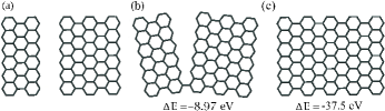
For our investigations we took two graphene flakes with linear zigzag or armchair edges and placed them side by side, as shown in Fig. 1 (a) and (d). After relaxation of the system, two flakes were merged along the stacked edges, thereby generating one flake of bigger size. The flakes with the linearly cut zigzag edges zip up along those zigzag edges (see (a-c) in Fig. 1) while in the other case the zipping occurred between the stacked armchair edges (see (d-f) in Fig. 1). We presented in Fig. 1 three major steps of the merging process: the separated flakes, origin of the zipping process, and the merged system. Zipping begins by moving the flakes close to each other by one seam with the formation of the first carbon-carbon bond between the two flakes (see (b,e) in Fig. 1) and after that the rest of the system zip up (see (c,f) in Fig. 1). To show that zipping occurs because it is the energetically favored process, we calculated the energy (see its value in Fig. 1) as the difference between the total energy of the original systems (Fig. 1 (a) or (d) for the zigzag and armchair edges, respectively) and the total energy of the structure taken in the current conformation. The energy grows as the flakes move close to each other (Fig. 1 (b) or (e) for the zigzag and armchair edges, respectively) due to the interaction between them, while subsequent formation of each carbon-carbon bond increases that energy even further.
Since formation of a large flake through zipping of two flakes of smaller size significantly lowers the total energy of the system, it implies that this process should occur with any flakes having the following characteristics: non-hydrogenated linear edges and ability to migrate. The evolution of the total energy with zipping of the flakes is defined not only by the zipping mechanism itself but by other parameters such as the original flake conformation and the distance between the flakes. However, to gain insight on the merging phenomena we need to estimate the energy released as each carbon-carbon bond is made. For this purpose we calculated the formation energy of the flake integration as , where is the total energy of the system after integration, while are the total energies of the initially separated first and second flakes, respectively. We found that in the case when zipping involves the zigzag edges (see (a-c) in Fig. 1), the formation energy was -43.99 eV, while for zipping along the armchair edges (see (d-f) in Fig. 1) =-51.20 eV. However, because the conformation of the graphene structure is different for the initial and final steps, the formation energy contains two major components and one of which is the energy released with the generation of each carbon-carbon bond while the second one is the reorganization energy of the lattice, i.e., the energy required to reorganize the graphene lattice with a transition of the system from the initial to final states. Therefore, to estimate the energy released by formation of the single carbon-carbon bond, we need to substitute the reorganization energy from the total formation energy. We calculated the reorganization energy to be -6.63 eV for merging of the flakes through zipping of the zigzag edges and -5.78 eV for flakes merging through zipping of the armchair edges. As a result we found that the formation energy of a single bond made between the zigzag edges is -6.22 eV. This value is close to that of the dissociation energy of the double carbon-carbon bonds which is 6.4 eV tut . For the armchair edges we obtained the formation energy of a single bond to be -5.92 eV, but this value can not be very accurate because in the case of zipping of the armchair edges the situation is more complicated as the armchair edges can not zip up completely without introducing some defected sites at the end of the line along which two flakes join (see Fig. 1 (f))
As it is impossible to merge the armchair edges without introducing the defected sites and because the zigzag edges seems to have a higher tendency to zip up than the armchair edges, the zipping along the zigzag edges should receive careful consideration for fabrication of large graphene films required for touch screens and solar cells technology techn_rev . For these applications, the effect of the flake size (finite size effects) should be an important concern. Because the lattice reorganization within the zipping process occurs mostly at the zipping edges the contribution of the reorganization energy to will gradually decrease with increasing length of the flake along the zipping edges. A similar conclusion was reached for the second energy component (linked with the formation of the carbon-carbon bonds) contributing to , i.e. will be reduced with an increase of the number of carbon-carbon bonds that are to be formed. Therefore, an increase in flake size, namely the flake length along the axis of zipping, would favor an increase of energy released in the process. Growth of the flake size in the other direction will not drastically modify the energetics of the zipping process. Moreover, the large formation energy of the carbon-carbon bond (-6.22 eV for the zigzag edges) suggests that the flake zipping would occur even at non-zero temperatures as this formation energy is much larger than the thermal energy (). The last conclusion is in fact, supported by the experimental observation of zipping of the damaged nanotubes nikolaev ; mitra .
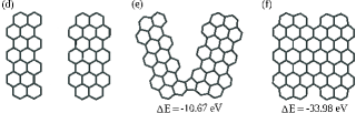
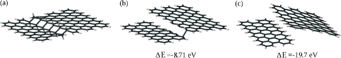
Because generation of each carbon-carbon bond releases so much energy, placing the flakes with linearly cut zigzag edges on top of each other may lead to occurrence of the zipping process at both sides limited by the zigzag edges thereby creating a nanotube. We performed the relaxation of the system presented in Fig. 2 (a) and achieved the rolling of the flakes into a nanotube (see Fig. 2 (d)). At first, the graphene flakes slowly bend into a tubular form (see Fig. 2 (c)) and with that bending the zigzag edges start to zip up (see Fig. 2 (d)). We calculated the energy of nanotube formation to be =-47.86 eV. Because there are twice the carbon-carbon bonds to be made to generate a nanotube from two flakes, it was expected that the energy released due to the tube formation should be much larger than that for integration of two flakes into one of bigger size. To confirm that we took the same flakes as in Fig. 2 (a) and placed them side by side, zipped them along their zigzag edges and calculated the formation energy to be =-36.58 eV. As expected, we found that the generation of a nanotube is much more favorable energetically in comparison to flakes merging into a flake of larger size. For flakes presented in Fig. 2 (a) the energy difference between the two final shapes (a nanotube in comparison to a flake) achieves the magnitude of -13.86 eV and this difference will grow with elongation of the nanotube structure. The reorganization energy in the case of the nanotube formation is quite small (-1.21 eV) which gives us the formation energy of the carbon-carbon bond to be -5.83 eV. In contrast, for the flakes merging into a flake of larger size, the reorganization energy remains significant (-10.66 eV) giving a bond formation energy of -6.48 eV.
Therefore, if there are two flakes with non-hydrogenated linear zigzag edges, depending on certain conditions they can form either a flake of larger size or a carbon nanotube. Obviously, the main condition controlling the final shape would be the mobility of the flakes and their original position relative to each other. Therefore, in a solution where the carbon systems presumably have higher mobility, the energetically favored shape of the carbon structure after annealing is expected to be a carbon nanotube. That is the reason for zipping of partially unzipped carbon nanotubes back to the original nanotube when its edges at the cutting front possess the dangling bonds tang . As formation of each carbon-carbon bond drastically lowers the total energy of the system, the process involving more bond formation would be favored energetically. Moreover, in a geometry of the carbon systems with less number of carbon atoms at the edges the total energy is lowered. In fact, this observation offers an understanding of the experimental data on coalescence of the carbon nanotubes in solution nikolaev . For example, we estimated that coalescence of two nanotubes (placed one behind other thereby forming a longer tube) of the same diameter equal to that in Fig. 2 (d) lowers the total energy by 51.34 eV.
Another important understanding is that the absence of hydrogenation at the edges makes the graphene flakes chemically attractive to each other. If interaction of the graphene flake with the surrounding environment can be considered as weak ber (because interaction with most of the adsorbates occurs via the van der Waals forces ort ), the interaction between the graphene flakes itself is quite significant and may lead to their integration. Therefore, if we are to prevent the integration of the carbon structures for their application in semiconductor electronics, they should be immobilized or being hydrogenated along the edges.
III Unzipping process
For graphene hydrogenation, the edges are the ones to be first hydrogenated because the energy required to attach a single hydrogen atom to the edges is about 3.0 eV less than that for hydrogen attachment to the graphene surface. Hydrogenation of graphene is a thermally activated process and is rarely found to occur at room temperature ker ; exp ; exp1 . Therefore, it is possible to hydrogenate the graphene edges selectively from the rest of the structure by controlling the temperature. For hydrogenation of the graphene surface, it appears that the conformation characterized by the lower total energy would be when the nearest-neighbor carbon atoms belonging to different sublattices (there are A and B sublattices in graphene review ) are hydrogenated from different sides of the graphene plane bouk . In this case the chemisorption energy is characterized by the lowest value and if the surface of graphene is fully hydrogenated, the system will turn into graphane in its chair conformation sofo ; galv .
For partial hydrogenation of the graphene surface, if the first hydrogen atom is randomly attached to the graphene surface, the second atomic hydrogen will be attached to the nearest-neighbor carbon atom as more energetically favorable position cas . Let us consider the process leading to the lowest state, i.e., to graphane in the chair conformation that occurs when hydrogenation is applied to both sides of the graphene plane. In this case, attaching the second hydrogen atom to the nearest-neighbor carbon atom with higher probability would occur at other side of the plane bouk . To continue the hydrogenation process we have to take into account the fact that the carbon atoms located closer to the already hydrogenated part requires less energy to be hydrogenated as this energy increases with increasing distance from the already hydrogenated carbon atoms cas . Because the pair of hydrogen atoms attached to the nearest-neighbor carbon atoms weakens the neighboring bonds, under some conditions of hydrogenation the attachment of hydrogen atoms may occur linearly (when minor difference in magnitude of the binding energy tends to control the hydrogenation process). As hydrogenation is a thermally activated process ker ; exp ; exp1 , such a control can be obtained at a lower temperature, while its substantial increase would actually lead to full hydrogenation of the graphene surface, i.e., to graphane-like structures. This effect of weakening of the neighboring bonds by an exposure to active adsorbates is used for longitudinal cutting of the carbon nanotubes by the oxidative process kosynkin ; xu and has been predicted to be the case in hydrogenation of the nanotubes lu .
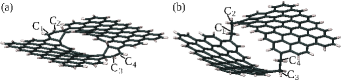
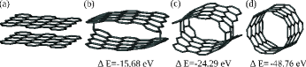
For three or more pairs of the hydrogenated carbon bonds forming a line as presented in Fig. 3 we found an interesting effect: The middle carbon-carbon bond from the line of hydrogenated atoms is being broken. To understand this behavior, we have to analyze the changes brought into the graphene lattice by hydrogenation. If two carbon atoms connected by the carbon-carbon bond are hydrogenated, it alters the hybridization of this bond from to , thereby enlarging its length from 1.42 Å to 1.52 Å bouk . As a result, the strength of such a carbon-carbon bond is significantly lowered. Moreover, hydrogenation causes the lattice distortion such that the carbon atoms hydrogenated from different sides of graphene are shifted out of its plane in opposite directions (in our present work it occurs along the - axis in Fig. 3 (b)). In the ideal honeycomb lattice the inter-atomic forces between the carbon atoms are almost compensated within the graphene plane (in this work the plane is formed in the and axes) and only the carbon atoms at the edges experience some compressive stress jun . However, the shift of the hydrogenated carbon atoms out of the plane leads to the appearance of the uncompensated inter-atomic forces arising on the modified bond and those forces are pointed out of the plane. The forces function as the tensile stress applied to the hybridized carbon-carbon bond (along the and axes) thus additionally reducing its strength. When there are three pairs of hydrogen atoms attached to the carbon atoms as presented in Fig. 3 (a), the tensile stress arising at the modified carbon bonds is actually weaker for the first and last pairs due to the compensation effect induced by the unmodified lattice around it. For the middle pair, the tensile stress is able to break the carbon-carbon bond.
We calculated the inter-atomic forces for the ideal graphene lattice and found that they are zero in the -direction, while in the and -axes they are almost compensated within the graphene plane (the remaining inter-atomic forces is 0.009 eV/Bohr of magnitude). Hydrogenation performed along the line as presented in Fig. 3 (a) in the -direction increases the existing forces on the hydrogenated carbon atoms up to 0.5 eV/Bohr, while in the -direction it causes an appearance of the inter-atomic forces of magnitude 0.9 eV/Bohr (shown as and in Fig. 3 (b)). Therefore, these forces in the and -axes are larger almost by two orders of magnitude than that in the ideal graphene lattice and the resulting tensile strain applied to the hybridized bond (see in Fig. 3 (b)) is 1.0 eV/Bohr from each side. Such a tensile strain appears to be large enough to break the weak hybridized carbon-carbon bond.
If we continue the line of hydrogenation presented in Fig. 3 (a) to the edges, will the tensile stress disintegrate the flake? We observed that the flake separation occurs only in the middle of the hydrogenation line (see Fig. 4 (a)) but not at the armchair edges (see the C1-4 carbon atoms in Fig. 4). Away from the edges the carbon atoms are connected to three nearest-neighbors and therefore, after their bonding with the hydrogen atom all their valence electrons are saturated thus converting the carbon-carbon bond into the hybridization type. However, the carbon atoms at the armchair edges have only two neighbors and their bonding with one hydrogen atom turns the C1-C2 and C3-C4 bonds into hybridization type (the bond length is 1.43 Å) instead of the required type. The termination of the C1-4 carbon atoms by the two hydrogen atoms (see Fig. 4 (b)) does not break the C1-C2 and C3-C4 bonds yet but lead only to their elongation (the bond length is 1.58 Å). To break these bonds the termination of the C1-4 carbon atoms (dangling after bond separation) by three hydrogen atoms is required which can not be done within the graphene lattice preceding the bond breaking (within the graphene lattice those carbon atoms have only two valence electrons left).

However, if the line of hydrogenation is shifted as in Fig. 5 (a), all the carbon atoms in the line are involved into bonding with three nearest-neighbors and attachment of the one extra hydrogen atom would indeed turn all the bonds into the hybridization type thereby causing their weakening and elongation. The tensile strain arising as a result of distortion of the graphene lattice breaks all the bonds that would lead to disintegration of the original flake (see Fig. 5 (b-c)). We calculated the evolution of the total energy () of the system as one flake is cut into two flakes. We obtained that its disintegration significantly lowers the total energy. After the cutting is done (see Fig. 5 (c)), the generated flakes take the position supporting the interaction of their dangling bonds left on the carbon atoms at the zigzag edges.
Technologically, it is easier to perform hydrogenation of the graphene flake from one side of the plane. Taking into account the great advantage offered by graphene cutting through its hydrogenation, we also investigated the behavior of the graphene system in the case of one-sided hydrogenation (see Fig. 6). We took the same flake as above and attached the hydrogen atoms at the same positions as in Fig. 5 but all from the same side of the plane. In the case of one-sided hydrogenation, the hydrogenated carbon atoms are shifted out of the plane but in the same direction (see Fig. 6 (a)). Similar to the double-sided hydrogenation, one-sided hydrogenation alters the hybridization of the carbon-carbon bonds from the to type. However, because the originated inter-atomic forces are all pointed in the same direction, they do not generate the tensile strain to the bonds but initiate the bending of the flake along the line of hybridized carbon-carbon bonds (see Fig. 6 (b)). At some point the stress arising at the bend is large enough to break these carbon-carbon bonds (see Fig. 6 (b)). After the bonds are broken, similarly to previous double-sided case presented in Fig. 5 (c), the disintegrated flakes migrate into the position which maximizes the interaction between the dangling bonds left on the carbon atoms at the zigzag edges that lowers the total energy of the system.
Therefore, for the planar graphene flakes if the carbon-carbon bonds are turned into the hybridization type by hydrogenation, it significantly lowers the strength of these bonds. Because hydrogenation induces lattice distortion thereby inhibiting the planarity of the flake, it causes the occurrence of the stress which is large enough to break the bonds if they form a line. If two sides of the graphene planes are involved in hydrogenation, the resultant stress works as the tensile strain applied to the bonds, while for one-sided hydrogenation, this stress initiates the flake bending that eventually breaks the bonds. The proposed in-line hydrogenation of graphene can be successfully applied to cut the graphene flakes in two or more pieces at the same time. Moreover, the same procedure can be used to unzip a carbon nanotube into a flake characterized by the ideal zigzag edges that is in agreement with previous investigations lu .
IV Conclusion
We have shown that hydrogenation not only plays an important role in defining the electronic properties of graphene review , it might also be used to control the graphene geometry. We found that flakes characterized by the linear and non-hydrogenated edges have the ability to merge into a bigger flake or a nanotube through zipping of their zigzag or armchair edges. Based on our results we suggest that a nanotube would be particularly characterized by the lower total energy because it has an energetically favorable shape. The energetic preference of a tubular shape comes from the large number of carbon-carbon bonds to be made within the zipping process than that for planar geometries. Formation of each carbon-carbon bond lowers the total energy of the system by 6 eV. This means that in case of high mobility of the carbon structures, to maintain the shape of others geometries such as graphene flakes, hydrogenation has to be applied to all the edges. However, hydrogenation of the graphene flakes has another tricky issue. If its application on the graphene surface creates the line of carbon-carbon bonds whose both atoms are hydrogenated, it can lead to a separation of the flakes into several pieces. The reason for such a behavior is that hydrogenation causes the alteration of the bond hybridization from to type that significantly suppresses the bond strength and the resulting stress turned on by lattice distortion under some conditions can be large enough to break those converted bonds. Such cutting of the graphene flakes can be performed through one-sided or double-sided hydrogenation of the graphene plane.
V Acknowledgments
The work has been supported by the Canada Research Chairs Program of the Government of Canada.
References
- (1) A. K. Geim and K. S. Novoselov, Nature Materials 6, 183 (2007).
- (2) For a review on the physics of graphene, see, D. S. L. Abergel, V. Apalkov, J. Berashevich, K. Ziegler, and T. Chakraborty, Adv. Phys. 59, 261 (2010).
- (3) C. Berger, Z. Song, T. Li, X. Li, A. Y. Ogbazghi, R. Feng, Z. Dai, A. N. Marchenkov, E. H. Conrad, P. N. First, and W. A. de Heer, J. Phys. Chem. B 108, 19912 (2004).
- (4) Z. Chen, Y.-M. Lin, M. J. Rooks and Ph. Avouris. Physica E 40, 228 (2007).
- (5) Y.-W. Son and S. G. Louie, Nature 444, 347 (2006).
- (6) J. Berashevich and T. Chakraborty, Phys. Rev. B 80, 115430 (2009).
- (7) O. V. Yazyev, W.L. Wang, S. Meng, and E. Kaxiras, Nano Lett. 8, 766 (2008).
- (8) K. S. Novoselov, A. K. Geim, S. V. Morozov, D. Jiang, Y. Zhang, S. V. Dubonos, I. V. Grigorieva, and A. A. Firsov, Science 306, 666 (2004).
- (9) X.L. Li, Science 319, 1229 (2008).
- (10) J. Campos-Delgado, J. M. Romo-Herrera, X. Jia, D.A. Cullen, H. Muramatsu, Y. A. Kim, T. Hayashi, Z. Ren, D. J. Smith, Y. Okuno, T. Ohba, H. Kanoh, K. Kaneko, M. Endo, H. Terrones, M.S. Dresselhaus, and M. Terrones, Nano Lett. 8, 2773 (2008).
- (11) N. Subbaraman, (2010) Flexible touch screen made with printed graphene. Technology review https://www.technologyreview.com/computing/25633/
- (12) J. Moon, K.H. An, Y. H. Lee, Y.S. Park, D.J. Bae, and G. S. Park, J. Phys. Chem. B 105, 5677 (2001).
- (13) R. Khare, S.L. Meilke, J.T. Paci, S. Zhang, R. Ballarini, G.S. Schatz, and T. Belytschko, Phys. Rev. B 75, 075412 (2007); S.M. Lee, E. Kim, C. Kim, J, Korean Phys. Soc. 54, 682 (2009); C. Tang, W. Guo, and C. Chen, Phys. Rev. B 83, 075410 (2011).
- (14) P. Nikolaev, A. Thess, A.G. Rinzler, D. T. Colbert, and R. E. Smalley, Chem. Phys. Lett. 266, 422 (1997).
- (15) M. Terrones, ACS Nano 4, 1775 (2010).
- (16) D. V. Kosynkin, A. M. Higginbotham, A. Sinitskii,J. R. Lomeda, A. Dimiev, B.K. Price, and J.M. Tour, Nature 458, 872 (2009).
- (17) L. Ci, Z. Xu, L. Wang, W. Gao, F. Ding, K. Kelly, B. Yakobson, and P. Ajayan, Nano Res. 1, 116 (2008).
- (18) A. L. Elías, A. R. Botello-Méndez, D. Meneses-Rodríguez, V. J. González, D. Ramírez-González, L. Ci, E. Muíoz-Sandoval, P. M. Ajayan, H. Terrones, and M. Terrones, Nano Lett. 10, 366 (2010).
- (19) R. Yang, L. Zhang, Z. Shi, D. Shi, H. Gao, E. Wang and G. Zhang, Advanced materials 22, 4014 (2010).
- (20) Jaguar, version 7.5. Schrödinger 2007. LLC: New York, NY.
- (21) M. Lozynski, D. Rusinska-Roszak, and H.-G. Mack, J. Phys. Chem. A. 102, 2899 (1998).
- (22) X. Jia, M. Hofmann, V. Meunier, B.G. Sumpter, J. Campos-Delgado, J.M. Romo-Herrera, H. Son, Y.-P. Hsieh, A. Reina, J. Kong, M. Terrones, and M. S. Dresselhaus, Science 323, 1701 (2009).
- (23) S. J. Blanksby and G.B. Ellison, Acc. Chem. Res. 36, 255 (2003).
- (24) N. Kulshrestha, A. Misra, K. S. Hazra, S. Roy, R. Bajpai, D. R. Mohapatra,and D. S. Misra, ACS Nano 5, 1724 (2011).
- (25) J. Berashevich and T. Chakraborty, Phys. Rev. B 80, 033404 (2009).
- (26) F. Ortmann, W.G. Schmidt, and F. Bechstedt, Phys. Rev. Lett. 95, 186101 (2005).
- (27) J. Kerwin and B. Jackson, J. Chem. Phys. 128, 084702 (2008).
- (28) S. Ryu, M. Y Han, J. Maultzsch, T. F. Heinz, P. Kim, M.L. Steigerwald, and L.E. Brus, Nano Lett. 8, 4597 (2008).
- (29) D. C. Elias, T. M. G. Mohiuddin, S. V. Morozov, P. Blake, M. P. Halsall, A. C. Ferrari, D. W. Boukhvalov, M. I. Katsnelson, A. K. Geim, and K. S. Novoselov, Science 323, 610 (2009).
- (30) D. W. Boukhvalov, M. I. Katsnelson, and A.I. Lichtenstein, Phys. Rev. B 77, 035427 (2008).
- (31) J. O. Sofo, A. S. Chaudhari, and G. D. Barber, Phys. Rev. B 75, 153401 (2007).
- (32) M. Z. S. Flores, P. A. S. Autreto, S. B. Legoas, and D.S. Galvao, Nanotechnology 20, 465704 (2009).
- (33) S. Casolo, O.M. Løvvik, R. Martinazzo, and G.F. Tantardini, J. Chem. Phys. 130, 054704 (2009).
- (34) Z. Hu and K. Xue, Nanotechnology 21, 045704 (2010).
- (35) G. Lu, H. Scudder and N. Kioussis, Phys. Rev. B 68, 205416 (2003).
- (36) S. Jun, Phys. Rev. B 78, 073405 (2008).