Charging of Superconducting Layers and Novel Type of Hysteresis in Coupled Josephson Junctions
Abstract
A manifestation of a novel type of hysteresis related to the parametric resonance in the system of coupled Josephson junctions is demonstrated. Opposite to McCumber and Steward hysteresis, we find that the width of this hysteresis is inversely proportional to the McCumber parameter and depends also on coupling between junctions and the boundary conditions. An investigation of time dependence of the electric charge in superconducting layers allow us to explain the origin of this hysteresis by different charge dynamics for increasing and decreasing bias current processes. The effect of wavelength of the longitudinal plasma waves created at the resonance on the charging of superconducting layers is demonstrated. We found a strong effect of the dissipation in the system on the amplitude of the charge oscillations at the resonance.
The hysteresis features of single Josephson junction (JJ) were studied by McCumber and Steward long time ago. mccumber68 ; steward68 Particularly, it was shown that the width of the hysteresis is directly proportional to the McCumber parameter related to the dissipation parameter by . In compare with the single Josephson junction, the system of the coupled Josephson junctions has a multiple branch structure and the definition of the return current is more general now: the system can return to the zeroth voltage state from any branch. The branches have a breakpoint (BP) and a breakpoint region (BPR) before transition to another branch. sm-prl07 The BP current characterizes the resonance point at which the longitudinal plasma wave (LPW) with a definite wave number k is created by Josephson oscillations in stacks. Hysteresis features of intrinsic JJ in high temperature superconductors have a wide interest also due to the observed powerful coherent radiation from such system. Ozyuzer In Ref. koyama09 the authors summarized the experimental results and stressed that the strong emission was observed near the unstable point of the return current in the uniform voltage branch. The radiation is related to the same region in the current voltage characteristics (CVC) where the BP and the BPR were observed and it made the phase dynamics investigation of intrinsic JJ corresponding to these parts of CVC an actual problem today.
Since thickness of superconducting layer (S-layer) in the intrinsic JJ is comparable to the Debye screening length, the S-layers are in the nonstationary nonequilibrium state due to the injection of quasiparticle and Cooper pairs. koyama96 ; ryndyk98 . The charge neutrality in S-layers is locally broken and this charging effect modifies the Josephson relation between voltage and the phase difference. The question concerning the value of the electric charge in S-layer and its maximum realized at the parametric resonance is not investigated yet.
In this paper we study the phase dynamics in coupled Josephson junctions. A novel type of hysteresis related to the parametric resonance in this system is demonstrated. We show that the width of this hysteresis is inversely proportional to the McCumber parameter and depends on coupling parameter of the system and the boundary conditions. The origin of this hysteresis is related to the different charge dynamics for increasing and decreasing bias current processes. We discuss the question concerning the maximal electric charge in S-layers realized at the resonance and show that it depends on the relation between the wavelength of LPW and the period of lattice. We demonstrate a strong effect of the dissipation in the system on the coefficient of the exponential growth of the maximal electric charge in S-layers.
First we discuss the phase dynamics in the system of coupled JJ. The CVC of JJs are numerically calculated in the framework of capacitively coupled Josephson junction model with diffusion current (CCJJ+DC) sms-physC06 . The system of equations for the gauge-invariant phase differences between -layers in this model has the form where is the phase of the order parameter in the S-layer , is the vector potential in the barrier, and are coupling and dissipation parameters, respectively, and . In our simulations we use both periodic and nonperiodic boundary conditions (BC). At nonperiodic BC it is suggested that the first and the last S-layers are in contact with normal metals and their effective width and may be extended due to the proximity effect into attached metals. Nonperiodic BC are characterized by parameter and the equations for the first and last layers in the system for phase differences are different from the equations for the middle S-layerskoyama96 ; matsumoto99 . We solve the system of dynamical equations for phase differences using the fourth order Rungge-Kutta method. We use a dimensionless time , where is the plasma frequency , is the critical current and is the capacitance. In our simulations we measure the voltage in units of and the current in units of the . The details concerning numerical procedure are given in Ref. 9.
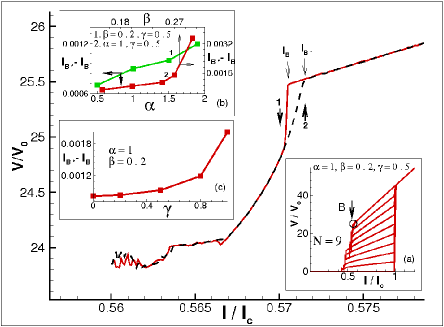
The results of simulation of CVC and its features near parametric resonance region are presented in Fig. 1. The inset (a) shows the total branch structure of the CVC for the stack with 9 JJ at , and . The CVC shows the following features: (i) a jump at from the zero voltage branch to the outermost branch with all junctions in the rotating state; (ii) practically linear dependence of the voltage on bias current at ; (iii) multiple branching in the hysteresis region. The circle and arrow with letter show the BP location on the outermost branch.
Fig. 1 demonstrates a hysteresis in the outermost branch of the CVC. It is obtained by decreasing the bias current till some point in the BPR (curve 1), then we increase the current to pass the resonance region (curve 2). The arrows show direction of the bias current changing. The hysteresis is characterized by its width , where is the value of breakpoint current in decreasing current process and is a characteristic current value in the increasing current process.
The dependence of the hysteresis width on the dissipation parameter is shown in the inset (b). The width is increasing with parameter (i.e., it is decreasing with the McCumber parameter). As we mentioned above, the McCumber and Steward hysteresis demonstrates an opposite behavior for single JJ. They obtained that the return current (which characterizes the value of hysteresis) decreases with increasing of the McCumber parameter.sm-physC06 So, we have observed a novel type of hysteresis related to the parametric resonance in coupled JJ. The insets (b) and (s) show as well an increase of the hysteresis width with the coupling parameter and parameter of nonperiodicity , respectively.
To make clear the origin of this hysteresis, we study time dependence of the charge oscillations in the S-layers. Using Maxwell equation Q, where and are relative dielectric and electric constants, we express the charge density in the S-layer by the voltages and in the neighbor insulating layers, where , and is Debay screening length. The charge dynamics in the S-layers determines the features of current voltage characteristics of the coupled Josephson junctions.
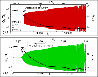
Solution of the system of dynamical equations for phase differences gives us the voltages as a functions of time (t) in all junctions in the stack, and it allows us to investigate the time dependence of the charge in each S-layer. Here we investigate the charge-time dependence for two processes: decreasing (Figs. 2(a), 3, 4, 5) and increasing (Fig. 2(b)) the bias current through the stack. The recorded time is calculated as for decreasing bias current process. For increasing current process (Fig. 2(b)) we record the time dependence at bias current value during the time interval (). We put mostly , and in our simulations.
In Fig. 2 the time dependence of the charge in S-layer of the stack with 9 coupled JJ at , and periodic BC is combined with the CVC of the outermost branch. Here and further we present the charge oscillations in the first S-layer of the stack: the features of the charge oscillations we are interested in this papers are the same in the all other layers. Fig. 2(a) shows the charge-time dependence when the current approaches the resonance point in decreasing current process, while Fig. 2(b) presents it when the bias current is increased. We can see that the charge on the S-layer in Fig. 2(b) disappears at different value of current in compare with the current value in decreasing process (Fig. 2(a)). We consider that it is an origin of the observed hysteresis, which is related to the parametric resonance in this system.
Let us now discuss the question concerning the amplitude of the electric charge oscillations in S-layer at parametric resonance (the parametric resonance corresponds to the BP on the outermost branch of CVC). Does its maximal value depend on the wavelength of created LPW? The Josephson oscillations excite the LPW with (-mode, wavelength ) at the parametric resonance in the stack with even number of JJ at , and periodic BC.sm-sust07 But in the stacks with odd number of JJ the wave number depends on and it is equal to . In the stacks with even number of JJ the resonance is ”pure”, i.e., no additional fine structure appears in CVC.sms-prb08 So, it is interesting to compare the maximal value of the electric charge realized in S-layers in this case with the case , where n is integer number.
In Fig. 3 we present time dependence of the electric charge in the S-layer for the stack with 10 JJ combined with the outermost branch of CVC (the corresponding axis are shown by arrows). We found that the bias current interval where the growing region (the beginning of that region is demonstrated in the inset (b)) of the electric charge in S-layers is observed, is shorter now in compare with N=9 case, where the LPW with is created at the same values of and . Compare this figure with Fig. 2, we can see that the amplitude of the charge is larger for the stack with even number of JJ. The inset (a) illustrates the charge distribution among the layers and confirms the -mode of LPW.
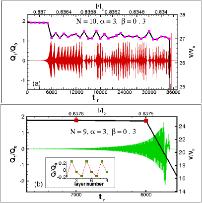
As we mentioned above, the wavelength of the LPW depends on the values of dissipation and coupling parameters.sm-prl07 So, we can compare the stacks with 10 and 9 JJ when another LPW are created and test the idea concerning the maximal amplitude of charge oscillations. In Fig. 4 the time dependence of the charge in the first S-layer at , and periodic BC combined with the CVC of the outermost branch is presented.
Fig. 4(a) shows this dependence for the stack with 10 junctions. At chosen parameters the LPW with is created. In case (Fig. 4(b)) the inset illustrates the charge distribution among the layers corresponding to the ()-mode (). Also we can see that the charge value on the S-layers in case is larger than in case of , which is the same result as we got before. In addition to that, we tested the cases for and ( not presented here) and they supported our idea. So, we may conclude that at fixed and the charge value in S-layers is larger for the stacks with ”pure” parametric resonance where the LPW with is created.
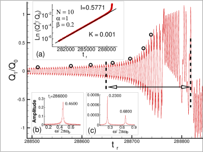
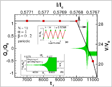
To demonstrate the character of the charge amplitude increasing in the growing region, we enlarged in Fig. 5 the charge-time dependence for the stack with 10 JJ at and = 0.2. In inset (a) we present the time dependence of the amplitude of in the logarithmic scale. The values of amplitude were taken arbitrary at some time moments in total growing region (examples are shown by circles). We found two parts in this dependence: exponential part and transition part (marked by double arrow) before jump to another branch. In transition part the amplitude demonstrates a sharp increase in short time interval in compare with exponential part. Insets (b) and (c) show results of FFT analysis of voltage and charge time dependence in the exponential grows part. They prove the parametric resonance condition . In transition part this condition is broken. Writing the expression for electric charge by , we find .
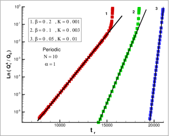
The Fig. 6 illustrates the influence of the dissipation magnitude ( = 0.2, 0.1, and 0.05) on time dependence of the charge oscillation amplitude in the logarithmic scale for the stack with 10 junctions at . From this figure we note the following features which are observed with decrease in (increase the McCumber parameter): i) the growing region is getting shorter; ii) the width of transition part is decreasing; iii) the coefficient of the exponential growth is increased. We come to the important conclusion that the parametric resonance features depend strongly on dissipation in the system. The width of the growing region is inversely proportional to the coefficient . The value of is determined by the wave number of LPW created at resonance. For all investigated stacks with even number of JJ (in our simulations we checked the stacks with in the interval (6,14)) at , and periodic BC we obtained the same value of .
In the supplement to this letter we include the avi files which present the animation of the charge dynamics in the different time moments in the growing region. These animation files demonstrate the standing of created LPW (the charge on the nearest neighbor layers has the same value and opposite sign) in the exponential part and its modification in the transition region.
As a summary, a manifestation of a novel type of hysteresis related to the parametric resonance in the system of coupled Josephson junctions is demonstrated. The width of this hysteresis is inversely proportional to the McCumber parameter and depends on coupling between junctions and the boundary conditions. The origin of this hysteresis is related to the different charge dynamics for increasing and decreasing bias current processes. We consider that these features are common for the systems demonstrating the parametric resonance. These features can be used to develop new methods for determination of coupling and dissipation parameters of the system. We show that the maximal value of electric charge amplitude realized in superconducting layers at the resonance depends on the wavelength of the created LPW. A strong effect of the dissipation in the system on the width of the parametric resonance is demonstrated.
We thank I. Rahmonov, M. Hamdipour, H. El Samman, S. Maize, M. Elhofy and Kh.Hegab for helpful discussions and support this work.
References
- (1) D. E. McCumber, J.Appl.Phys. 39, 3113 (1968).
- (2) W. C. Steward, Appl.Phys.Lett. 12, 277 (1968).
- (3) Yu. M. Shukrinov and F. Mahfouzi, Phys. Rev. Lett. 98, 157001 (2007).
- (4) L. Ozyuzer et al., Science 318, 1291 (2007).
- (5) T. Koyama, H. Matsumoto, M. Machida, and K. Kadowaki, Phys. Rev. B 79, 104522 (2009).
- (6) D. A. Ryndyk, Phys. Rev. Lett. 80, 3376 (1998).
- (7) T. Koyama and M. Tachiki, Phys. Rev. B 54, 16183 (1996).
- (8) Yu. M. Shukrinov, F. Mahfouzi, and P. Seidel, Physica C 449, 62 (2006).
- (9) H. Matsumoto, S. Sakamoto, F. Wajima, T. Koyama, M. Machida, Phys. Rev. B 60, 3666 (1999).
- (10) Yu. M. Shukrinov and F. Mahfouzi, Physica C 434 (2006) 6-12.
- (11) Yu. M. Shukrinov and F. Mahfouzi, Supercond. Sci. Technol. 20, S38 (2007).
- (12) Yu. M. Shukrinov, F. Mahfouzi, M. Suzuki, Phys. Rev. B 78, 134521 (2008).