Status and Recent Results of the Acoustic Neutrino Detection Test System AMADEUS
Abstract
The AMADEUS system is an integral part of the ANTARES neutrino telescope in the Mediterranean Sea. The project aims at the investigation of techniques for acoustic neutrino detection in the deep sea. Installed at a depth of more than 2000 m, the acoustic sensors of AMADEUS are based on piezo-ceramics elements for the broad-band recording of signals with frequencies ranging up to 125kHz. AMADEUS was completed in May 2008 and comprises six “acoustic clusters”, each one holding six acoustic sensors that are arranged at distances of roughly 1m from each other. The clusters are installed with inter-spacings ranging from 15 m to 340 m. Acoustic data are continuously acquired and processed at a computer cluster where online filter algorithms are applied to select a high-purity sample of neutrino-like signals. 1.6 TB of data were recorded in 2008 and 3.2 TB in 2009. In order to assess the background of neutrino-like signals in the deep sea, the characteristics of ambient noise and transient signals have been investigated. In this article, the AMADEUS system will be described and recent results will be presented.
keywords:
AMADEUS , ANTARES , Neutrino telescope , Acoustic neutrino detection , Thermo-acoustic modelPACS:
95.55.Vj , 95.85.Ry , 13.15.+g , 43.30.+m1 Introduction
The AMADEUS project [1] was conceived to perform a feasibility study for a potential future large-scale acoustic neutrino detector. For this purpose, a dedicated array of acoustic sensors was integrated into the ANTARES neutrino telescope [2, 3].
Measuring acoustic pressure pulses in huge underwater acoustic arrays is a promising approach for the detection of cosmic neutrinos with energies exceeding 100 PeV. The pressure signals are produced by the particle cascades that evolve when neutrinos interact with nuclei in water. The resulting energy deposition in a cylindrical volume of a few centimetres in radius and several metres in length leads to a local heating of the medium which is instantaneous with respect to the hydrodynamic time scales. This temperature change induces an expansion or contraction of the medium depending on its volume expansion coefficient. According to the thermo-acoustic model [4, 5], the accelerated motion of the heated volume—a micro-explosion—forms a pressure pulse of bipolar shape which propagates in the surrounding medium. Coherent superposition of the elementary sound waves, produced over the volume of the energy deposition, leads to a propagation within a flat disk-like volume (often referred to as pancake) in the direction perpendicular to the axis of the particle cascade. After propagating several hundreds of metres in sea water, the pulse has a characteristic frequency spectrum that is expected to peak around 10 kHz [6, 7, 8].
Two major advantages over an optical neutrino telescope motivate studying acoustic detection. First, the attenuation length in sea water is about 5 km (1 km) for 10 kHz (20 kHz) signals. This is one to two orders of magnitude larger than for visible light with a maximum attenuation length of about 60 m. The second advantage is the more compact sensor design and simpler readout electronics for acoustic measurements. Since on the other hand the speed of sound is small compared to the speed of light, coincidence windows between two spatially separated sensors are correspondingly large. Furthermore, the signal amplitude is relatively small compared to the acoustic background in the sea, resulting in a high trigger rate at the level of individual sensors and making the implementation of efficient online data reduction techniques essential. To reduce the required processing time without sacrificing the advantages given by the large attenuation length, the concept of spatially separated clusters of acoustic sensors is used in the AMADEUS system. Online data filtering is then predominantly applied to the closely arranged sensors within a cluster.
It is important to realise that there are two kinds of background which need to be understood to assess the feasibility of an acoustic neutrino detector: First, there is ambient noise which can be described by its characteristic power spectral density. This noise is determined by environmental processes and defines the minimum pulse heights that can be measured, if a given signal-to-noise ratio can be achieved with a search algorithm. Second, there are neutrino-like events, i.e. signals which have the characteristic bipolar pulse shape but have a different origin. It is important to measure the spatial, temporal and pulse-height distribution of such bipolar events in order to asses the probability for random coincidences that mimic the characteristic pancake structure of a neutrino sound wave. For this kind of measurement, a hydrophone array is required and the synchronisation among the hydrophones is crucial.
This article is organised as follows: In Sec. 2 an overview of the ANTARES neutrino telescope is given and in Sec. 3 the AMADEUS system is described. In Sec. 4 the properties at the ANTARES site are discussed which are responsible for the sound propagation in the sea. In Sec. 5 first results of the measurement of the ambient noise are presented while in Secs. 6 and 7 the position calibration of the AMADEUS sensors and the direction reconstruction of acoustic sources, respectively, are discussed. These measurements are prerequisites to determine a density of bipolar events in the Mediterranean Sea. In the subsequent sections, further steps are discussed before conclusions are drawn.
2 The ANTARES Detector
The AMADEUS system [1] is integrated into the ANTARES neutrino telescope [2, 3], which was designed to detect neutrinos by measuring the Cherenkov light emitted along the tracks of relativistic secondary muons generated in neutrino interactions. A sketch of the detector, with the AMADEUS modules highlighted, is shown in Figure 1. The detector is located in the Mediterranean Sea at a water depth of about 2500 m, roughly 40 km south of the town of Toulon on the French coast at the geographic position of 42∘48′ N, 6∘10′ E. It was completed in May 2008 and comprises 12 vertical structures, the detection lines. Each detection line holds up to 25 storeys that are arranged at equal distances of 14.5 m along the line, starting at about 100 m above the sea bed and interlinked by electro-optical cables. A standard storey consists of a titanium support structure, holding three Optical Modules [9] (each one consisting of a photomultiplier tube (PMT) inside a water-tight pressure-resistant glass sphere) and one Local Control Module (LCM). The LCM consists of a cylindrical titanium container and the off-shore electronics within that container. It comprises a compass board that measures the tilt and the orientation of the storey. Timing correlations between storeys on a sub-nanosecond level are provided by a clock system that provides a master clock signal from a shore station, distributed optically to the individual LCMs over a dedicated set of fibres.
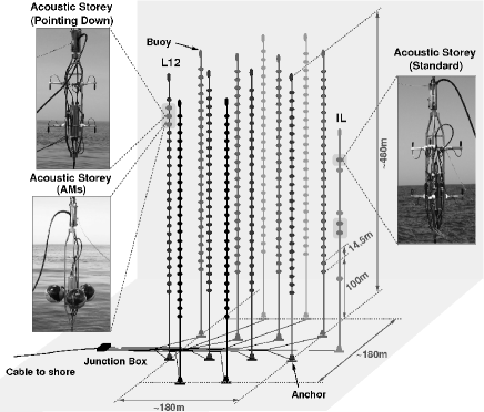
A 13th line, called Instrumentation Line (IL), is equipped with instruments for monitoring the environment. It holds six storeys. For two pairs of consecutive storeys in the IL, the vertical distance is increased to 80 m. Each line is fixed on the sea floor by an anchor equipped with electronics and held taut by an immersed buoy. An interlink cable connects each line to the Junction Box from where the main electro-optical cable provides the connection to the shore station.
The ANTARES lines are free to swing and twist in the undersea current. In order to determine the positions of the storey with a precision of about 20 cm—which is necessary to achieve the required pointing precision for neutrino astronomy—the detector is equipped with an acoustic positioning system [10]. The system employs an acoustic transceiver at the anchor of each line and four autonomous transponders positioned around the 13 lines. Along each detection line, five positioning hydrophones receive the signals emitted by the transceivers. By performing multiple time delay measurements and using these to triangulate the positions of the individual hydrophones, the line shapes can be reconstructed relative to the positions of the emitters. Currently, the sequence of positioning emissions is repeated every 2 minutes.
3 The AMADEUS System
3.1 Overview
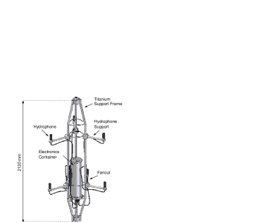
In AMADEUS, acoustic sensing is integrated in the form of acoustic storeys that are modified versions of standard ANTARES storeys, in which the Optical Modules are replaced by custom-designed acoustic sensors. The acoustic storeys are the implementation of the acoustic clusters discussed above. The AMADEUS system uses the standard ANTARES facilities whenever possible, e.g. the hardware and software for the data transmission to shore, the clock system, and the software to operate the detector. Dedicated electronics is used for the amplification, digitisation and pre-processing of the analogue signals. Figure 2 shows the design of a standard acoustic storey with hydrophones. Six acoustic sensors per storey were implemented, arranged at distances of roughly 1 m from each other. This number was the maximum compatible with the design of the LCM and the bandwidth of data transmission to shore. The data are digitised with 16 bit resolution and 250 k samples per second.
The AMADEUS system comprises a total of six acoustic storeys: three on the IL, which started data taking in December 2007, and three on the 12th detection line (Line 12), which was connected to shore in May 2008. AMADEUS is now fully functional and routinely taking data with 34 sensors. Two out of 36 hydrophones became inoperational during their deployment.
The acoustic storeys on the IL are located at 180 m, 195 m, and 305 m above the sea floor. On Line 12, which is anchored at a horizontal distance of about 240 m from the IL, the acoustic storeys are positioned at heights of 380 m, 395 m, and 410 m above the sea floor. With this setup, acoustic sensors are installed at water depths between 2050 and 2300 m and the maximum distance between two acoustic storeys is 340 m. AMADEUS hence covers three length scales: spacings of the order of 1 m between sensors within a storey (i.e. an acoustic cluster); intermediate distances of 14.5 m between adjacent acoustic storeys within a line; and large scales from about 100 m vertical distance on the IL up to 340 m between storeys on different lines. The AMADEUS system includes time synchronisation and a continuously operating data acquisition setup and is in principle scalable to a large-volume detector.
3.2 Acoustic Sensors
Two types of sensing devices are used in AMADEUS: hydrophones and Acoustic Modules [1, 11]. The acoustic sensors employ in both cases piezo-electric elements for the broad-band recording of signals with frequencies ranging up to 125 kHz. For the hydrophones, the piezo elements are coated in polyurethane, whereas for the Acoustic Modules they are glued to the inside of standard glass spheres which are normally used for Optical Modules.
The measurements presented here were done with the hydrophones; The acoustic modules are described elsewhere [1, 11]. The typical sensitivity of the hydrophones is around 145 dB re 1V/Pa (including preamplifier). Different types of hydrophones are installed in AMADEUS, all of which have a diameter of 38 mm and a length (from the cable junction to the opposite end) of 102 mm. The equivalent inherent noise level in the frequency range from 1 to 50 kHz is about 5.4 mPa for the AMADEUS hydrophones with the smallest such noise. This compares to 6.2 mPa of the lowest expected ambient noise level in the same frequency band for a completely calm sea [12], referred to as sea state 0 [13].
3.3 On-Shore Data Processing
An on-shore computer cluster is used to process and filter the data stream and store the selected events. The system is operating continuously and automatically, requiring only little human intervention. It currently consists of four server-class computers, of which two with a total of 12 cores are used for data triggering111While this functionality might be more commonly referred to as filtering, it is ANTARES convention to refer to the “on-shore trigger”.. One of the remaining two computers is used to write the data to an internal 550 GB disk array, while the other is used to operate the software for the online control of the data acquisition and other miscellaneous processes and to provide remote access to the system via the Internet.
The AMADEUS trigger searches the data by an adjustable software filter; the events thus selected are stored to disk. This way the raw data rate of about 1.5 TB/day is reduced to about 10 GB/day for storage. Currently, three trigger schemes are in operation [1, 14]: A minimum bias trigger which records data continuously for about 10 s every 60 min, a threshold trigger which is activated when the signal exceeds a predefined amplitude, and a pulse shape recognition trigger. For the latter, a cross-correlation of the signal with a predefined bipolar signal, as expected for a neutrino-induced cascade, is performed. The trigger condition is met if the output of the cross-correlation operation exceeds a predefined threshold. With respect to a matched filter, this implementation reduces the run time complexity while yielding a comparable trigger performance.
In total, 1.6 TB of data were recorded in 2008 and 3.2 TB in 2009.
4 Properties of the Mediterranean Sea
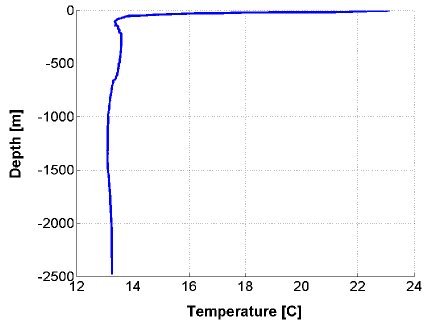
The speed of sound in water depends on its temperature, salinity, and pressure (i.e. depth). A measurement of the temperature vs. the depth at the ANTARES site conducted in summer of 2007 is shown in Fig. 3. Only the upper 100 m of the water are affected by seasonal variations and below that depth, the temperature is quite stable, ranging from 13.1 ∘C to 13.6 ∘C. Consequently, sound channelling is not a significant effect for acoustic measurements at the ANTARES site. This is quite different from the situation in oceans, where typically the uppermost kilometre of water shows a temperature decrease with depth.
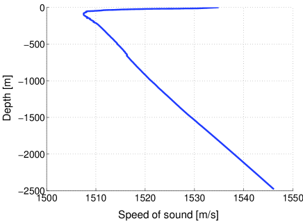
The sound speed profile as a function of depth is shown in Fig. 4. Once the temperature is stable, the speed of sound increases almost linearly with depth. Assuming an open water model, i.e. assuming that the temperature gradient and the depth of the sea surrounding ANTARES do not vary, the furthest distance from which an acoustic signal originating from the surface can reach the AMADEUS device is about 30 km. The refracted signal will reach the uppermost sensor from an angle of about , i.e. from below a horizontal plane. A signal originating at the surface and reaching the detector within a horizontal plane will have a distance of about 20 km. The open water model is an approximation that is not valid for directions towards the coast. In northwards direction, for instance, the water depth is reduced to about 200 m within roughly 10 km.
5 Ambient Noise
To measure the ambient background present at the ANTARES site, one sensor on the IL07 was evaluated from December 5, 2007 to January 22, 2010, i.e. over a period of about 2 years. During this time, a total of 18462 minimum bias samples (each one containing data continuously recorded over a timespan of 10 s) was recorded.
Removing samples with large components at high frequencies (e.g. containing signals from the acoustic positioning system and non-Gaussian distributions) 13909 samples (75.4%) are remaining. For each of these samples, the noise power spectral density (PSD) was integrated in the frequency range kHz. The resulting noise values, relative to the mean noise over all samples, are shown in Fig. 5 as a function of the time of the day. Two clear peaks can be observed at about 2 a.m. and 9 p.m.; while the origin of this structure can not yet be undoubtedly determined, the most likely source is shipping traffic.
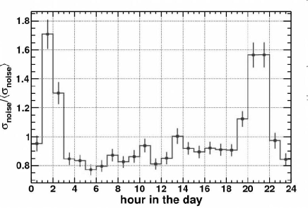
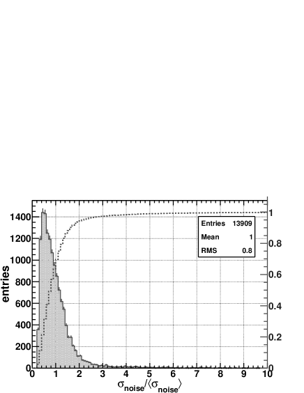
Figure 6 shows the frequency of occurrence distribution of the same values. Also shown is the corresponding accumulative distribution. For 95% of the samples, the noise level is below , demonstrating that the ambient noise conditions are very stable.
All sensors have been calibrated in the laboratory prior to deployment. The absolute noise level can be estimated by assuming a constant sensor sensitivity222 The ambient noise is originating mainly from the sea surface and hence displays a directivity which has to be folded with the variations of the sensitivity over the polar angle to obtain an effective average sensitivity. For the results presented here, the noise has been assumed to be isotropic. of dB re 1V/Pa. With this value, the mean noise level is mPa with the median of the distribution at mPa. It must be understood that these noise levels correspond to the specific frequency range chosen. The frequency range used for this study is not optimised for the spectral shape of the expected neutrino signal. Clearly, the noise level can be made arbitrarily small by choosing a correspondingly small frequency range. The most sensible procedure is to choose the frequency range that optimises the signal-to-noise ratio (SNR) for the expected neutrino signal. Preliminary studies using the shower parametrisation and algorithms presented in [7] indicate that this range is about 10 to 50 kHz. The AMADEUS minimum bias data show that the RMS noise of 25 mPa for kHz reduces to about 7.5 mPa for kHz, i.e. by a factor of about 0.3. The estimate for the energy sensitivity of the AMADEUS device given below, based on the frequency range of kHz, therefore has to be understood as a conservative upper bound. A more realistic energy sensitivity is obtained by applying the factor of 0.3 to scale the results to the smaller frequency range.
Currently, the detection threshold for bipolar signals corresponds to a SNR of about two for an individual hydrophone. By applying pattern recognition methods that are more closely tuned to the expected neutrino signal, this threshold can possibly be reduced. For a SNR of two, the noise value of below which % of the data can be found corresponds to a signal amplitude of 100 mPa, which corresponds to a neutrino energy of 10 EeV at a distance of 200 m [6]. Scaling this result to the reduced frequency range, and using the median noise level of it can be estimated that for 50% of the time, the energy threshold is at 1 EeV or below for a distance of 200 m.
In summary, the ambient noise conditions are very favourable for acoustic neutrino detection in the Mediterranean Sea: The noise level is stable at an expected level. Hence it will be crucial to determine the density of bipolar events to assess the feasibility of an acoustic neutrino detector. A prerequisite for the position reconstruction of acoustics sources is the position calibration of the acoustic storeys which will now be described.
6 Position Calibration
Just as for the PMTs in the standard storeys, the relative positions of the acoustic sensors within the detector have to be continuously monitored. This is done by using the emitter signals of the ANTARES acoustic positioning system. The emission times of the positioning signals are recorded in the central ANTARES database. Measuring the reception time within the acoustic sensors of the AMADEUS system allows for the calculation of the distance between emitter and receiver. Using the signals from multiple emitters and the knowledge of their positions at the anchors of the lines, the positions of the AMADEUS sensors can be reconstructed. And finally, from the reconstructed positions of the individual sensors, the six degrees of freedom (centre of mass coordinates and the three Euler angles) of each storey can be obtained.
Figure 7 shows the comparison of the heading as measured with the acoustic sensors on a storey and the compass board installed in that storey. The heading is defined as the rotational angle of the storey around the vertical axis, relative to a well defined reference horizontal axis within the storey. A heading of zero degrees then corresponds to the reference axis pointing north, with angles counting clockwise from to . The periodic structure of the heading is due to the sea currents which change in accordance to the Coriolis force, which at a geographic latitude affects the direction of sea currents with a period of , where h is the period of a sidereal day on Earth and therefore h.
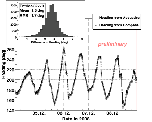
Both the acoustic measurement and the measurement of the compass board have an offset of their zero degree position w.r.t. the cardinal direction of north: When measuring zero degrees, the compass board points to the North Magnetic Pole while the direction derived from the acoustic measurements points along the northing axis of the UTM grid. At the location of ANTARES, this difference is 2.5∘ where the UTM northing axis points further westwards than the direction of the North Magnetic Pole. The difference shown in Fig 7 is not corrected for these offsets, the mean value of the distribution after this correction is therefore . The offsets from the six storeys have a spread of about around zero.
The RMS deviation between the two measurements is 1.7∘ (0.03 rad) or 3% w.r.t. the distance of a source from the line. Here the residual offset between compass board and angle reconstruction with the AMADEUS sensors were ignored. On the other hand, the RMS deviation is the quadratic sum of the resolution of the compass board and of the AMADEUS measurement, resulting in an overestimation of the RMS resolution. Since the two effects are of about the same size, they will roughly cancel out.
For a measurement of the density of bipolar events, the absolute positioning of the acoustic storeys is not important. The precision of the measurement of source positions (which then determines the error of the density and limits the distance up to which a surveillance is possible) is determined by the resolution of the angular reconstruction of a source position and by that of the distance between the storeys. The horizontal distance between the IL07 and Line 12 is about 240m. Preliminary studies, comparing the positions that are reconstructed with AMADEUS and with the ANTARES positioning system, indicate that the distance between the centre of mass positions of two storeys on the two lines can be reconstructed with a precision of much better than 1 m. The resulting precision of 1% indicates that the dominant contribution to the error on the position reconstruction will stem from the angular resolution of the source position reconstruction (see the following section).
7 Source Direction Reconstruction
The sensors within a cluster allow for efficient triggering of transient signals and for direction reconstruction. The combination of the direction information from different acoustic storeys yields (after verifying the consistency of the signal arrival times at the respective storeys) the position of an acoustic source [15].
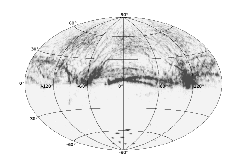
Figure 8 shows the reconstructed directions of all sources that were triggered during a period of one month. One can observe dark bands of increased acoustic activity. These bands can be associated with shipping routes and the points with high activities with the directions of ports. Note that in accordance with the arguments given in Sec. 4, the ports themselves are too far away to record acoustic signals directly, unless reflection at the sea bottom and surface occur, which would then however strongly reduce the signal strength. It is obvious from Fig. 8 that a fiducial volume for the determination of the background rate of bipolar events must exclude the sea surface.
The resolution of the reconstruction is about 3∘ in azimuth () and 0.5∘ in the polar angle () [16]. While the source direction reconstruction uses methods similar to those used for the position reconstruction with AMADEUS, for the latter typical emitters are used which increases the statistics and hence the precision. Note that for both methods the error includes the resolution of the compass board.
8 Further Steps
Using the direction reconstruction from several storeys, source position reconstruction can be performed. First investigations over a three month period show that a detailed classification of events triggered by the pulse shape recognition trigger (see Sec. 3.3) is necessary to reduce the background of neutrino-like events [16]. Several methods for this signal classification are currently under investigation [17].
Furthermore, Monte Carlo code is under development, based on the software and method presented in [7]. This will allow for testing the classification and calculating efficiencies for the classification of neutrino events.
9 Conclusions
Recent results from the acoustic neutrino detection test system AMADEUS have been presented. The measurement of the ambient noise over a period of about two years shows that the noise level is very stable and at the expected level, allowing for measurements of neutrino energies down to 1 EeV. The AMADEUS system has all features of an acoustic neutrino telescope, except for its size. As would be necessary for a potential future acoustic neutrino telescope in water, position calibration of its acoustic sensors, which are swaying with the underwater sea currents, are routinely performed with AMADEUS. For individual acoustic storeys, comprising six acoustic sensors each, reconstruction of acoustic source directions is done with an angular resolution of about in azimuth.
Current focus of the analysis work is the further classification of transient bipolar events to minimise the irreducible background for neutrino searches. In addition, work on MC simulations is in progress to test these classification methods and to calculate efficiencies for neutrino detection.
In summary, the system is excellently suited to assess the background conditions for the measurement of the bipolar pulses expected to originate from neutrino interactions. The AMADEUS system can furthermore be used as a multi purpose device to perform positioning and marine science investigations in addition to studies of neutrino detection.
10 Acknowledgements
This study was supported by the German government through BMBF grants 5CN5WE1/7 and 05A08WE1. Furthermore, the author wishes to thank the organisers of the ARENA 2010 workshop for an enjoyable and instructive event.
References
- [1] J.A. Aguilar et al. (ANTARES Coll.), doi:10.1016/j.nima.2010.09.053, to be published by Nucl. Instr. and Meth. A, arXiv:1009.4179v1 [astro-ph.IM].
- [2] The ANTARES Collaboration, ANTARES, the first operational Neutrino Telescope in the Mediterranean Sea, to be submitted to Nucl. Instr. and Meth. A.
- [3] M. Ageron et al. (ANTARES Coll.), Astropart. Phys. 31 (2009) 277, arXiv: 0812.2095 v1 [astro-ph].
- [4] G.A. Askariyan, B.A. Dolgoshein et al., Nucl. Instr. and Meth. 164 (1979) 267.
- [5] J. Learned, Phys. Rev. D 19 (1979) 3293.
- [6] S. Bevan et al. (ACoRNE Coll.), Astropart. Phys. 28 (3) (2007) 366, arXiv:astro-ph/0704.1025v1.
- [7] S. Bevan et al. (ACoRNE Coll.), Nucl. Instr. and Meth. A 607 (2009) 389, arXiv:0903.0949v2 [astro-ph.IM].
- [8] V. Niess and V. Bertin, Astropart. Phys. 26 (2006) 243, arXiv:astro-ph/0511617v3.
- [9] P. Amram et al. (ANTARES Coll.), Nucl. Instr. and Meth. A 484 (2002) 369.
- [10] M. Ardid for the ANTARES Coll., in: Proceedings of VLVnT 2008, the 3rd International Workshop on a Very Large Volume Neutrino Telescope for the Mediterranean Sea, Vol. A 602, 2009, p. 174.
- [11] C.L. Naumann, Development of sensors for the acoustic detection of ultra high energy neutrinos in the deep sea, Ph.D. thesis, Univ. Erlangen-Nürnberg, 2007, FAU-PI4-DISS-07-002.
- [12] K. Graf, Experimental studies within ANTARES towards acoustic detection of ultra-high energy neutrinos in the deep sea, Ph.D. thesis, Univ. Erlangen-Nürnberg, 2008, FAU-PI1-DISS-08-001.
- [13] R.J. Urick, Ambient Noise in the Sea, Peninsula publishing, Los Altos, USA, 1986, ISBN 0-932146-13-9.
- [14] M. Neff, Studie zur akustischen Teilchendetektion im Rahmen des ANTARES-Experiments: Entwicklung und Integration von Datennahmesoftware, Diploma thesis, Univ. Erlangen-Nürnberg, 2007, FAU-PI1-DIPL-07-003.
- [15] C. Richardt et al., Astropart. Phys. 31 (2009) 19, arXiv:0906.1718v1 [astro-ph.IM].
- [16] C. Richardt, Acoustic particle detection - Direction and source location reconstruction techniques, Ph.D. thesis, Univ. Erlangen-Nürnberg, 2010, FAU-ECAP-DISS-10-003.
- [17] M. Neff, these proceedings.