Energy deposition studies for the Neutrino Factory target station
Abstract
A study of the energy deposition in the Neutrino Factory baseline target station is presented. FLUKA simulations are used to study how much of the 4 MW proton beam power is distributed within the target station, and these results are compared with MARS simulations. About 10% of the beam power is deposited in the mercury jet target, with more than 2 MW absorbed by the tungsten-carbide shielding. Heating in the superconducting coils, that generate most of the magnetic field in the target region, can be substantially reduced by increasing the surrounding shielding. Estimates of radiation damage are also given for different sections of the target geometry.
keywords:
Radiation calculations; Targets (spallation source targets, radioisotope production, neutrino and muon sources)1 Introduction
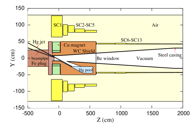
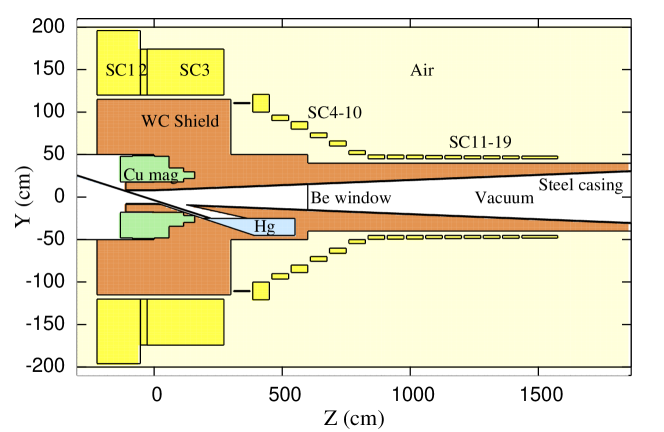
The current baseline option for the Neutrino Factory is to use a 4 MW proton beam interacting with a free-flowing mercury jet to create an intense muon beam. The MERIT experiment has shown a proof-of-principle demonstration of a high intensity liquid mercury jet target [1]. Figure 1 shows a schematic of the Neutrino Factory target station. The interaction of the proton beam with the mercury jet creates low-energy pions that are captured by the high field ( T) solenoid and transported into a decay channel where the muons resulting from pion decay are collected and stored until they decay to neutrinos.
Despite the success of the MERIT experiment, further work was necessary to investigate how the 4 MW beam power is distributed inside the target station so that adequate shielding can be put in place to protect vulnerable systems such as the superconducting magnets. This paper presents a study of the power deposition and radiation environment of the Neutrino Factory target station using FLUKA [2] simulations. Also shown are comparisons with results from MARS [3, 4] simulations.
2 Simulation Parameters
As a starting point, the Neutrino Factory mercury jet target station geometry is based on the Study 2a configuration [5], as shown in figure 1, with the appropriate 20 T field map based on the dimensions and currents in the normal conducting copper ( T) and superconducting coils ( T). Variations to the geometry are made to investigate whether the energy deposition in the superconducting magnets can be reduced. The proton beam has a Gaussian profile with a root mean square radius of 1.2 mm, and is tilted by approximately 100 mrad with respect to the magnetic ( axis. The kinetic energy of the proton beam is nominally set to 8 GeV, while the mercury jet is modelled as a simple cylinder with a radius of 4 mm. The angle between the mercury jet and the proton beam at their intersection ( cm) is 27 mrad, which is chosen to optimise the production of useful low-energy pions from the target [6].
3 Study 2a geometry
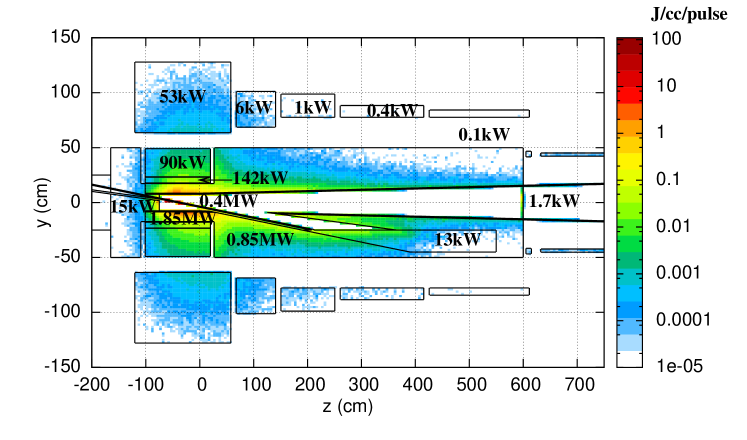
Figure 2 shows that the power from the 4 MW proton beam is distributed throughout the whole target station volume, with more than half of the total power deposited in the water-cooled tungsten-carbide (WC) shielding. About 10% of the total power is deposited in the mercury jet, with high energy deposition also seen in the normal conductor magnet coils. The major concern is that about 53 kW of power is absorbed by the first superconducting coil surrounding the target (SC1), as well as significant power deposition observed for some of the other coils. This heat load is extremely high, with an estimated peak power of 70 mW/cc (10 mW/g) for SC1, which is beyond the design guidelines for a maximum superconducting heat load less than 1 mW/cc for the International Thermonuclear Experimental Reactor (ITER) [7]. The amount of heat deposited in the superconducting coils increases when the tungsten-carbide shielding (80% WC and 20% water) is replaced with either pure tungsten, mercury or a combination of the two (see table 1). Increasing the shielding volume from an outer radius of 50 cm to 63 cm, up to the SC1 inner boundary (enhanced shielding option), helps to reduce the heat loads in the coils by approximately a factor of three, but this is still inadequate.
| Shielding Material | SC1 | SC1-SC13 | Shielding |
|---|---|---|---|
| 80% WC + 20% Water | 54 | 64 | 2293 |
| 100% W | 57 | 70 | 2231 |
| 80% W + 20% Hg | 63 | 80 | 2199 |
| 60% W + 40% Hg | 69 | 91 | 2171 |
| 100% Hg | 87 | 134 | 2083 |
The heat load estimates shown above are consistent with those found using MARS simulations [4], except for the superconducting coils, which are a factor of two higher. Investigations of the energy deposition in simple target geometries show that the particle (hadronic) showers in FLUKA are more penetrating than those in MARS. Further studies show that much better agreement is achieved when the MCNP mode [8] for MARS is enabled, giving a consistent treatment of the transport of very low energy (thermal) neutrons, with a kinetic energy cut-off of GeV, that can pass through the shielding and deposit energy in the superconducting coils.


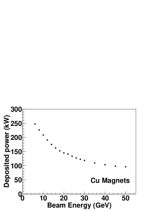
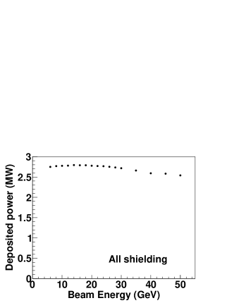
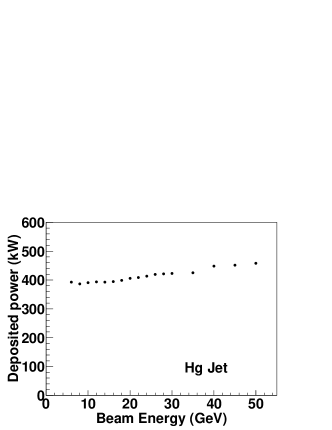

The variation of the deposited power in several regions of the target station, with enhanced shielding up to a radius of 63 cm, as a function of the initial proton beam kinetic energy is shown in figure 3, all for a total beam power of 4 MW (the proton rate is inversely proportional to the input kinetic energy). Beam energies below 5 GeV are not considered here, since FLUKA uses another hadron-nucleon model to simulate the beam-target interaction that differs to the one used at higher energies. For the magnet coils, the deposited power is reduced as the proton beam energy increases. The overall power absorbed by the shielding stays roughly constant, and there is only a slight increase in the deposited power in the mercury jet at higher beam energies. In contrast, the heat dissipation from secondary particle interactions in the mercury pool dramatically increases with input energy. Note that the energy of the mercury jet will also be absorbed by the mercury pool as the jet flows into it, so the effective energy deposition for the mercury flow system is the sum of the separate jet and pool contributions. From these results, it is obvious that the problems of significant energy deposition in the superconducting coils can not be solved by just changing the beam energy, slightly adjusting the shielding volume or modifying the material used in the shielding.
4 Increased shielding geometry
The results shown earlier demonstrate that the original Study 2a geometry for the Neutrino Factory target station suffers from a number of problems regarding energy deposition. Specifically, the first few superconducting coils experience a radiation dose that is too high for their safe operation. We will show that this can been mitigated by effectively doubling the outer radius of the shielding protecting the inside of the superconducting magnets.
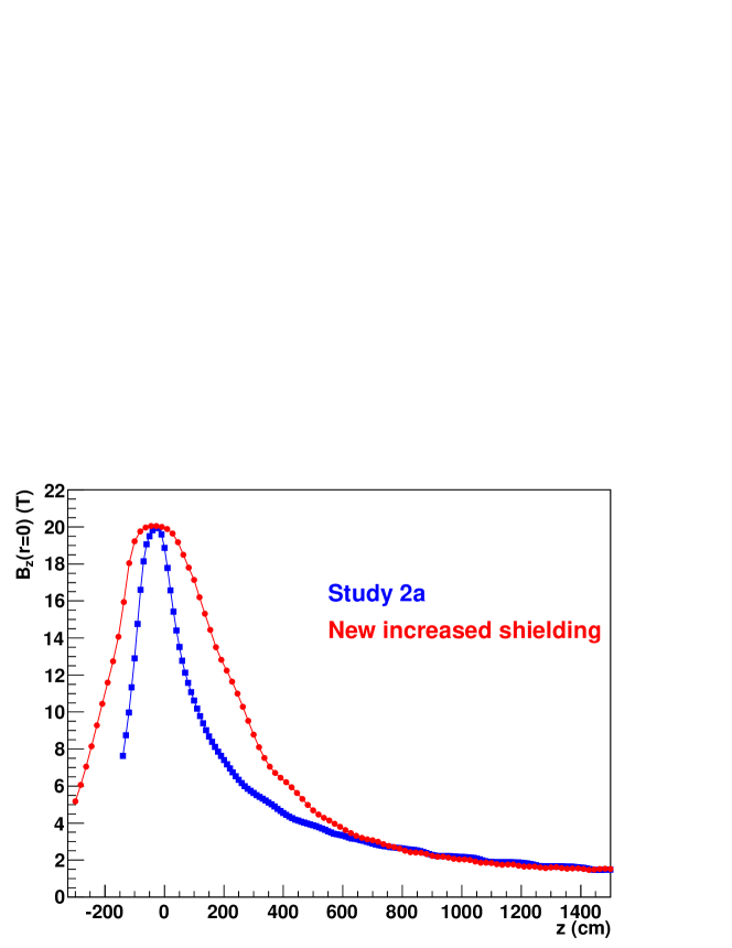
Figure 4 shows a schematic of a new target station geometry which contains substantially increased shielding to limit the heat deposition in the coils, whose inner radii have been increased from 63 cm to 120 cm. Note that the layout of all of the coils has been changed to ensure that the magnetic field at the beam-target interaction region ( cm) peaks at 20 T. The parameters defining the new coil positions and current densities, as a result of the work presented in [9], are shown in table 2. A comparison of the magnetic field along the axis, , between the Study 2a and increased shielding geometries is shown in figure 5. For the new geometry, the magnetic field distribution has a broader peak, but has a field taper for greater than 600 cm that closely matches the taper from the Study 2a geometry. The tungsten-carbide shielding contains a larger fraction of cooling water (40%), while the iron plug just behind the normal conductor coils has been removed for simplicity. The same 8 GeV proton beam and mercury jet parameters are used as before.
| Label | (cm) | (cm) | (cm) | (cm) | (A/mm2) | Material |
|---|---|---|---|---|---|---|
| NC1 | -131.3 | 47.3 | 17.8 | 30.2 | 16.6 | Cu |
| NC2 | -84.0 | 86.2 | 17.8 | 30.9 | 16.6 | Cu |
| NC3 | 2.1 | 56.2 | 17.8 | 30.3 | 16.6 | Cu |
| NC4 | 58.3 | 57.0 | 17.8 | 16.6 | 16.6 | Cu |
| NC5 | 115.3 | 43.5 | 21.9 | 8.0 | 16.6 | Cu |
| SC1 | -222.6 | 169.4 | 120.0 | 75.9 | 23.2 | Nb3Sn |
| SC2 | -53.1 | 26.1 | 120.0 | 54.0 | 23.2 | Nb3Sn |
| SC3 | -27.1 | 300.0 | 120.0 | 54.1 | 23.1 | Nb3Sn |
| SC4 | 310.0 | 65.0 | 110.0 | 1.2 | 30.0 | Nb3Sn |
| SC5 | 385.0 | 65.0 | 100.0 | 20.8 | 33.3 | Nb3Sn |
| SC6 | 460.0 | 65.0 | 90.0 | 6.4 | 35.9 | Nb3Sn |
| SC7 | 535.0 | 65.0 | 80.0 | 8.7 | 38.2 | Nb3Sn |
| SC8 | 610.0 | 65.0 | 70.0 | 5.6 | 40.0 | Nb3Sn |
| SC9 | 685.0 | 65.0 | 60.0 | 6.1 | 40.0 | Nb3Sn |
| SC10 | 760.0 | 65.0 | 50.0 | 4.7 | 40.0 | NbTi |
| SC11 | 835.0 | 65.0 | 45.0 | 4.6 | 40.0 | NbTi |
| SC12 | 910.0 | 65.0 | 45.0 | 4.4 | 40.0 | NbTi |
| SC13 | 985.0 | 65.0 | 45.0 | 4.3 | 40.0 | NbTi |
| SC14 | 1060.0 | 65.0 | 45.0 | 3.9 | 40.0 | NbTi |
| SC15 | 1135.0 | 65.0 | 45.0 | 3.8 | 40.0 | NbTi |
| SC16 | 1210.0 | 65.0 | 45.0 | 3.5 | 40.0 | NbTi |
| SC17 | 1285.0 | 65.0 | 45.0 | 3.5 | 40.0 | NbTi |
| SC18 | 1360.0 | 65.0 | 45.0 | 3.4 | 40.0 | NbTi |
| SC19 | 1435.0 | 140.0 | 45.0 | 3.2 | 40.0 | NbTi |
| Region | Power (kW) |
|---|---|
| SC1 | |
| SC2 | |
| SC3 | |
| SC4 | |
| SC5 | |
| SC6 to SC10 | |
| SC11 to SC19 | |
| Inner shielding cm, m | |
| Shielding m, cm | |
| Downstream shielding m | |
| SC shield cm | |
| Inner shield casing m | |
| Inner shield casing m | |
| Hg jet | |
| Hg pool | |
| NC1 | |
| NC2 | |
| NC3 | |
| NC4 | |
| NC5 | |
| 4 mm Be window at 6 m |
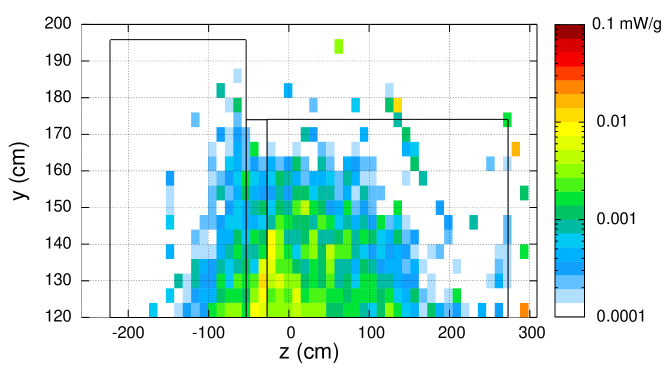
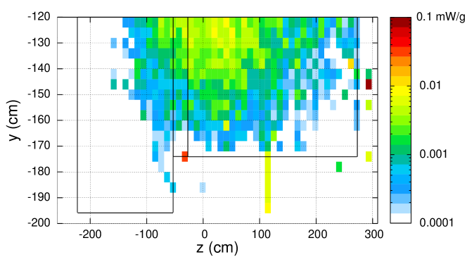
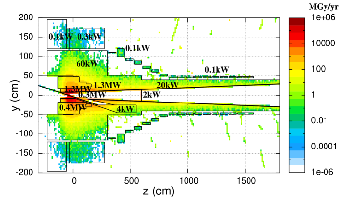
Figure 6 shows the estimated total radiation dose in units of Gy for s/year (to be conservative), while table 3 shows the deposited power in various regions of the new target station, where the uncertainties are estimated by using different initial random number seeds for the FLUKA simulation. We can immediately see that the power depositions in the superconducting coils have all been reduced to values below 1 kW, with the maximum value around 0.3 kW occurring for the third coil. The extended shielding for cm stops 60 kW of heat from reaching the first few superconducting coils. The combined shielding still absorbs just over half of the total beam power, with around 8% deposited in the mercury jet. However, the heat loads in the normal conducting copper coils located inside the shielding volume, whose lengths have approximately doubled, have increased by a factor of two.
Figure 7 shows a close-up view of the deposited power per unit mass for the first three superconducting coils (SC1–3). Slightly more energy is deposited in the region since the proton beam is pointing down in this direction. The peak energy density for SC3 is less than 0.05 mW/g, which is below the ITER requirement of 0.17 mW/g [7], assuming a conductor mass density of 6 g/cc. This peak energy deposition is equivalent to Gy/year (for a year of s), which is well below the estimated maximum allowed integrated dose of Gy [5], meaning that the coils should have sufficient operational lifetime. These results are consistent with those obtained using MARS with the MCNP mode enabled [10].
A major concern with the new target station design is that there will be a four-fold increase in the stored energy of the magnets approaching 1 GJ. This energy needs to be managed safely in the event of a quench, in which a section of the magnet becomes too hot, losing its superconductivity and affecting other nearby coils. The larger radius of the coils also means that the magnetic forces ( k kTonnes) between them increases, causing difficulties for the overall magnet support structure [11]. To help with the significant engineering challenges, it may be necessary to reduce the achievable magnetic field in the target interaction region, involving a trade-off between magnet construction feasibility and an acceptable loss of useful low-energy pions from the target.
5 Radiation damage
The target station will be a high radiation environment, and it is important to know how this will affect various materials used in its construction. For instance, radiation damage to the superconducting coils will severely limit their operational capability, and may even make them inoperable. One measure of this damage is the average number of displacements per atom (DPA) inside a material. For example, a radiation dose of 2 DPA means that each atom in the material has been displaced within the structural lattice an average of two times. Here, the DPA values for several regions of the new target station geometry are estimated using an empirical model based on the LSS theory of atomic collisions in solids [12, 13]. In this model, a (Frenkel) defect forms when an atom is given energy and leaves its place in the atomic lattice, displacing nearby atoms in a cascade effect. The initial displaced atom is known as the primary knock-on atom (PKA). The number of defects (per incident proton) is given by
| (1) |
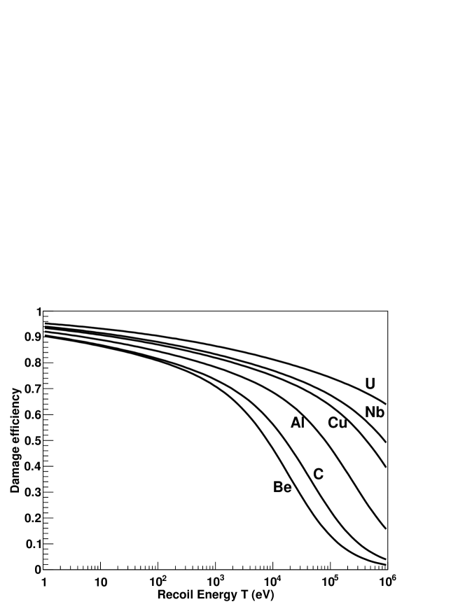
where is the kinetic energy of the PKA, which we assume is equal to the amount of deposited energy, is the partition function describing how the initial energy displaces other atoms within the cascade, is the damage threshold energy, which is the minimum energy needed to displace an atom within the lattice, and is the displacement efficiency. Example values of are 10 eV for beryllium, 40 eV for copper and niobium, and 90 eV for tungsten. The factor of two in the denominator is due to the fact that the model assumes that the energy in each two-body collision within the cascade is shared equally. Figure 8 shows the distribution of the partition function , also known as the damage efficiency, for several materials. In general, heavier atomic mass elements have larger values for a given kinetic energy . The total number of DPA per year is then given by
| (2) |
where is the average value of per proton, is the atomic density, is the volume of the given material region, and is the total number of protons on target per year ( s), which is equal to /year for a 4 MW, 8 GeV proton beam.
Using the previous energy deposition results for the new target geometry, we find that an upper limit of the radiation dose for the superconducting magnets (assuming Nb-Nb atomic collisions dominate) is approximately DPA/year. This is about a factor of ten lower than the critical operational dose of for radiation (neutron) damage that can cause irreversible reductions of allowed currents in Nb3Sn superconducting coils [14]. However, there will need to be ceramic insulating shielding for the magnet conductors, and it is not known at present how they may be damaged by the radiation dose. For comparison, the radiation dose for the first superconducting coil (SC1) in the Study 2a geometry is estimated to be DPA/year, which is equal to the critical dose.
The peak radiation doses for the normal conducting magnets and the shielding in the new geometry are approximately 0.2 DPA/year and 1.2 DPA/year, respectively. The steel casing along the inside of the shielding (“beam pipe”) suffers a radiation dose of DPA/year close to the interaction region, which lowers to a value below 0.1 DPA/year further downstream.
A potential concern is that a radiation dose of 0.9 DPA/year is estimated for the 4 mm beryllium window, which is located at m to stop mercury (liquid and vapour) and rare gas reaction products from going further downstream. Such a dose may deform the window, and there will also be significant production of tritium, which has a half-life around 12 years and is a potential radiation hazard. This means that the window will need to be regularly replaced in order to protect the downstream components of the Neutrino Factory accelerator system.
The activation of the mercury jet system will be dominated by the production of mercury isotopes, although there will also be significant isotope production of nearby elements such as gold, platinum and iridium, all of which typically decay within a few hours or days. The large number of different isotopes in the mercury jet system may cause material compatibility concerns for the mercury return flow and nearby cooling loops.
6 Failure modes
It is important to know how the beam power will be distributed within the target station for a range of failure modes, such as if there is a complete failure of the magnetic field () or the mercury jet stops flowing and the full 4 MW proton beam goes straight into the mercury pool reservoir and shielding beam dump. Table 4 shows comparisons of the average power deposition in various regions of the new target station geometry between normal and extreme operating conditions.
| Region | Normal | No | No Hg jet | No & No Hg jet |
|---|---|---|---|---|
| SC1 | ||||
| SC2 | ||||
| SC3 | ||||
| SC4 | ||||
| SC5 | ||||
| SC6 to SC10 | ||||
| SC11 to SC19 | ||||
| Shielding | ||||
| Inner shield casing | ||||
| Hg jet | — | — | ||
| Hg pool | ||||
| NC1 to NC5 | ||||
| 4 mm Be window |
With no magnetic field present to steer the proton beam (and any secondary charged particles), the energy deposition for the combined mercury jet and pool system increases by a factor of . In addition, the downstream superconducting coils see a large increase in radiation dose, but this can be reduced to safe levels by introducing an additional conic frustum to the shielding for to 6 m, with a radius between 50 and 100 cm. Note that the power deposited in the mercury jet itself decreases, owing to the fact that the proton beam, which is no longer bending in the magnetic field, intersects a smaller mercury target volume. If no mercury jet is flowing, then most of the beam power (80%) is dumped in the water-cooled tungsten-carbide shielding and inner beam pipe steel casing. The presence of the magnetic field and the geometry of the surrounding region ensures that little energy is deposited in the mercury pool reservoir. In contrast, with no magnetic field and no mercury jet present, the mercury pool experiences a large thermal shock equivalent to just below half of the total beam power. This will produce significant agitation of the mercury pool surface with splashes of radial velocities expected to approach 50 m s-1 [15].
Concerning the calculation of DPA values, it will be advantageous to quantify the radiation doses within much smaller regions of the target station geometry in order to identify local hot-spots of radiation damage. In addition, an improved model for calculating DPA values to much better accuracy is required. During the time of this study, the FLUKA simulation package did not have this capability, but such a feature is expected to be made available in the near future.
7 Summary
We have shown that a lot of shielding is required to protect the superconducting coils from large radiation doses in the Neutrino Factory target station, as provided by the current versions of the FLUKA and MARS simulation codes. This, however, poses additional engineering challenges for the magnet support design. The shielding absorbs about half of the total beam power, which will have to be handled by any water cooling system. There will be significant energy deposition for the normal conducting magnets, and the beam pipe casing close to the interaction region will experience large radiation doses. There may also be safety issues with the radiation dose expected for the beryllium window protecting the rest of the decay channel from mercury liquid/vapour. The energy deposition results are essentially unchanged if the mercury jet is assumed to only have an effective length of 30 cm, equivalent to approximately two interaction lengths. Finally, we should expect to observe similar levels of radiation dose throughout the whole target station if we replace the mercury jet with a solid or powdered jet target made of tungsten.
8 Acknowledgements
We acknowledge the financial support of the European Community under the European Commission Framework Programme 7 Design Study: EUROnu, Project Number 212372. The EC is not liable for any use that may be made of the information contained herein. I also thank my colleagues from the International Design Study (IDS-NF) collaboration for fruitful discussions concerning this work.
References
- [1] K. T. McDonald et al., The MERIT high-power target experiment at the CERN PS, in proceedings of First International Particle Accelerator Conference, Kyoto Japan, May 23–28 2010, pg. 3527.
-
[2]
G. Battistoni et al.,
The FLUKA code: description and benchmarking, in proceedings of
Hadronic Shower Simulation Workshop 2006,
Fermilab, Batavia U.S.A. September 6–8 2006,
AIP Conf. Proc. 896 (2007) 31;
A. Fasso, A. Ferrari, J. Ranft and P.R. Sala, FLUKA: a multi-particle transport code, CERN-2005-10, CERN, Geneva Switzerland (2005) [SLAC-R-773];
The official FLUKA site: FLUKA homepage, http://www.fluka.org/fluka.php. -
[3]
N. V. Mokhov, The MARS code system user’s guide,
Fermilab-FN-628, Fermilab, Batavia U.S.A. (1995);
N. V. Mokhov et al., Recent enhancements to the MARS15 code, Fermilab-Conf-04/053, Fermilab, Batavia U.S.A. (2004);
MARS homepage, http://www-ap.fnal.gov/MARS. - [4] X. Ding, H. Kirk and J. S. Berg, A pion production and capture system for a 4MW target station, in proceedings of First International Particle Accelerator Conference, Kyoto Japan May 23–28 2010, pg. 4272.
- [5] S. Geer and M. Zisman eds., Neutrino Factory and beta beam experiments and development (feasibility study IIa), Technical Report, BNL-72369-2004, (2004) [physics/0411123].
- [6] J. Strait, N. V. Mokhov and S. I. Striganov, Towards the optimal energy of the proton driver for a neutrino factory and muon collider, Phys. Rev. ST Accel. Beams 13 (2010) 111001 [arXiv:1011.2537].
- [7] ITER Team collaboration, K. Tomabechi, ITER: design overview, J. Nucl. Mat. 179-181 (1991) 1173.
- [8] X-5 Monte Carlo Team, MCNP - a general Monte Carlo N-particle transport code, version 5, volume I: overview and theory, LA-UR-03-1987, Los Alamos National Laboratory, Los Alamos U.S.A. (2003).
-
[9]
R. Weggel,
Preliminary analysis of the target system magnets,
http://www.hep.princeton.edu/mumu/target/weggel/weggel_113010.pdf, BNL Solenoid Capture Workshop, New York U.S.A. November 29–30 2010. -
[10]
N. Souchlas,
Shielding studies for the muon collider target,
http://www.hep.princeton.edu/mumu/target/Souchlas/souchlas_113010.pdf, BNL Solenoid Capture Workshop, New York U.S.A. November 29–30 2010. -
[11]
P. Loveridge,
Technical challenges of the Neutrino Factory capture system,
http://www.hep.princeton.edu/mumu/target/Loveridge/loveridge_113010.pdf, BNL Solenoid Capture Workshop, New York U.S.A. November 29–30 2010. - [12] J. Lindhard, M. Scharff and H. E. Schiøtt, Range concepts and heavy ion ranges, K. Dan. Vidensk. Selsk. Mat. Fys. Medd. 33 (1963) 1.
- [13] M. T. Robinson, Basic physics of radiation damage production, J. Nucl. Mat. 216 (1994) 1 and references therein.
- [14] C. L. Snead, D. M. Parkin and M. W. Guinan, High-energy-neutron damage in Nb3Sn: changes in critical properties, and damage-energy analysis, J. Nucl. Mat. 103 (1981) 749.
- [15] A. Fabich and J. Lettry, Experimental observation of proton-induced shocks and magneto-fluid-dynamics in liquid metal, Nucl. Instrum. Meth. A 503 (2003) 336.