Forced and self-excited oscillations of an optomechanical cavity
Abstract
We experimentally study forced and self-excited oscillations of an optomechanical cavity which is formed between a fiber Bragg grating that serves as a static mirror and between a freely suspended metallic mechanical resonator that serves as a moving mirror. In the domain of small amplitude mechanical oscillations, we find that the optomechanical coupling is manifested as changes in the effective resonance frequency, damping rate and cubic nonlinearity of the mechanical resonator. Moreover, self-excited oscillations of the micromechanical mirror are observed above a certain optical power threshold. A comparison between the experimental results and a theoretical model that we have recently derived and analyzed yields a good agreement. The comparison also indicates that the dominant optomechanical coupling mechanism is the heating of the metallic mirror due to optical absorption.
I Introduction
Studies combining mechanical elements in optical resonance cavities Braginsky and Manukin (1967); Hane and Suzuki (1996) experience a significant surge in popularity in recent years due to the fast progress made in both microelectromechanical systems (MEMS) and optical microcavities. For example, optomechanical coupling of nanomechanical mirror resonators to optical modes of high-finesse cavities mediated by radiation pressure has a promise of bringing the mechanical resonators into the quantum realm Kimble et al. (2001); Carmon et al. (2005); Arcizet et al. (2006); Gigan et al. (2006); Jayich et al. (2008); Schliesser et al. (2008); Genes et al. (2008); Kippenberg and Vahala (2008); Teufel et al. (2010). Furthermore, the micro-optoelectromechanical systems (MOEMS) are expected to play an increasing role in optical communications Wu et al. (2006) and other photonics applications Stokes et al. (1990); Lyshevski and Lyshevski (2003); Hossein-Zadeh and Vahala (2010).
In addition to the radiation pressure, another important force that contributes to the optomechanical coupling in MOEMS is the bolometric force Metzger and Karrai (2004); Jourdan et al. (2008); Metzger et al. (2008); Marino and Marin (2010); Ludwig et al. (2007); Restrepo et al. (2010); Liberato et al. (2010), also known as the thermal force. This force can be attributed to the thermoelastic deformations of the micromechanical mirrors. In general, the thermal force plays an important role in relatively large mirrors, in which the thermal relaxation rate is comparable to the mechanical resonance frequency. Phenomena such as mode cooling and self-excited oscillations have been shown in systems in which this force is dominant Metzger et al. (2008); Metzger and Karrai (2004); Aubin et al. (2004); Jourdan et al. (2008). Existing theoretical models that describe these phenomena quantitatively Aubin et al. (2004); Marquardt et al. (2006); Paternostro et al. (2006); Ludwig et al. (2007); Liberato et al. (2010) are based on energy or harmonic balance methods which provide good predictions of the system steady state, but lack the ability to fully describe its complex dynamics.
Recently, we have developed a slow envelope dynamical model of an optomechanical system which includes radiation pressure, thermal force, and changes to mechanical frequency due to absorption heating Zaitsev et al. (2011a). The theoretical predictions, which are derived using a combined harmonic balance and averaging method Szemplińska-Stupnicka (1990), include all the experimental phenomena shown by optomechanical systems with a bolometric force, such as linear dissipation renormalization and self-excited oscillations. In addition, the model enables prediction of additional nonlinear effects, namely, the change in the sign of the mechanical cubic nonlinear elastic and dissipative terms as function of the optical power incident on the cavity and its exact detuning from resonance Aubin et al. (2004).
Here, we present experimental results that demonstrate all the major dynamical phenomena which are theoretically implied in Ref. Zaitsev et al. (2011a). In order to facilitate the study of optical cavities with micromechanical mirrors spanning a wide range of different geometries and materials, we employ a fiber Bragg grating (FBG) Snyder and Love (1983) as a static mirror of the optical cavity. The wave length dependent transparency of the FBG allows us to achieve different coupling conditions between the optical mode inside the cavity and the incident light, thus effectively controlling the cavity’s finesse.
A very reasonable fit between theory and experiment is achieved using two distinct geometries of the micromechanical mirror composed of two different metals - AuPd and aluminum. The fits include changes in the linear dissipation, the threshold, the frequency and the amplitude of self-excited oscillations, and the thermally induced frequency shifts under different conditions. In addition, we show optically induced changes in the nonlinear response of the micromechanical mirrors.
II Experimental setup
In the investigated system, an optical resonance cavity is created between a suspended metallic micromechanical mirror, which is free to oscillate in a direction parallel to the optical axis, and a stationary mirror in the form of a FBG as shown in Fig. 1. The system is located in a vacuum chamber inside a cryostat with a typical pressure of and temperature of .
A micromechanical mirror is fabricated on a silicon-nitride membrane using electron beam lithography and thermal evaporation of metal. Following these steps, the membrane is removed by electron cyclotron resonance (ECR) plasma etching, and the micromechanical mirror becomes suspended. This fabrication process is similar to the one described in Buks and Roukes (2001).
Two main suspended mirror configurations were used in our experiments, a gold-palladium () rectangular mirror and an aluminum doubly clamped wide beam. The dimensions of the devices are given in Fig. 1.
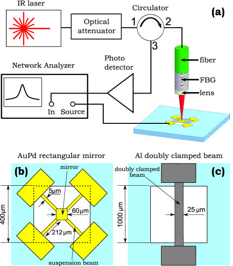
The micromechanical mirror can be actuated capacitively in the direction of the optical axis by applying voltage between the mirror and the ground plate of the package used to mount the sample in the vacuum chamber. The ground plate is parallel to the mirror and located below it.
The FBG, which has a length of , is formed using a phase mask having a period of on a single mode optical fiber having effective refractive index of near the wavelength of . A microlens made from a section of a graded index fiber having length of pitch is spliced to the the end of the fiber Mao et al. (2007). A brief analysis of the FBG’s optical properties is given in Sec. III.1.
The optical fiber can be moved in three orthogonal directions by the means of piezomotors with an accuracy of approximately . Generally, the fiber is positioned above the center of the micromechanical mirror at a focal distance of the microlens, which is . The length of the optical cavity can be changed by moving the fiber along the optical axis. We control the wavelength and the power of the light incident on the cavity by using a variable wavelength infra-red laser and a variable fiber-optic attenuator, respectively. The light reflected off the cavity back into the fiber is separated by the means of a circulator and converted to an electrical signal by a photodetector. The experimental system is shown in Fig. 1.
The finesse of the optical cavities created in the presented experiments is of order of ten. We estimate the optical relaxation time to be of order . It follows that optical retardation can be neglected in our system, and thus the optical energy stored in the cavity is a function of the momentary displacement of the micromechanical mirror.
III Theoretical model
An extensive theoretical analysis of the dynamics of a micromechanical oscillator acting as a mirror in a low finesse optical cavity based on a slow envelope approximation can be found in Ref. Zaitsev et al. (2011a). Here, we state the main results from that work, and present a short discussion on the FBG optical properties.
III.1 Optical cavity
The finesse of the optical cavity is limited by loss mechanisms that give rise to optical energy leaking out of the cavity. The main escape routes are through the FBG, through absorption by the metallic mirror, and through radiation, and the corresponding transmission probabilities are respectively denoted by , and . The transmission probability through the FBG is evaluated using the coupled mode theory Snyder and Love (1983); Poladian (1996)
| (1) |
where is the normalized detuning factor, and are respectively the laser and Bragg angular frequencies, is light velocity in vacuum, and is the FBG coupling constant.
Let be the displacement of the mirror relative to the point , at which the energy stored in the optical cavity in steady state obtains a local maximum. For a fixed the cavity reflection probability , i.e. the ratio between the reflected (outgoing) and injected (incoming) optical powers in the fiber, is given by
| (2) |
where is the distance between two successive resonance positions of the micromechanical mirror (i.e., half the wavelength), and
is the full width at half maximum parameter. The effective optical power impinging on the suspended micromechanical mirror can be expressed as
| (3) |
where
is the maximum optical power incident on the mirror, is the power of the monochromatic laser light incident on the cavity, and
is the resonant enhancement factor of the intra-cavity power. Note that for the case of critical coupling, i.e., the case where , .
The optical power is a periodic function, which can be approximated by a truncated Fourier series
| (4) |
where should be of order of the finesse or larger for the truncation error to be negligible. As shown in Ref. Zaitsev et al. (2011a), , where , , and .
III.2 Equations of motion
The micromechanical mirror can be approximately described as a harmonic oscillator with a single degree of freedom operating near primary resonance, which is subject to several forces arising from coupling to the optical resonance cavity. In general, a stand alone micromechanical resonator can exhibit nonlinear behavior Lifshitz and Cross (2008); Zaitsev et al. (2011b). In our experiments, however, the contributions of purely mechanical nonlinearities are negligible, as will be shown in Sec. V.3.
Following Ref. Zaitsev et al. (2011a), we write the equation of motion as
| (5) |
where a dot denotes differentiation with respect to time , is the mechanical resonance frequency of the mirror, is the mechanical quality factor, is the temperature dependent momentary resonance frequency, is the external excitation force, and is a small detuning of the external excitation frequency from , i.e., . The forces resulting from coupling to an optical resonance cavity are the radiation pressure , and , which is a thermal force that appears due to temperature dependent deformation of the micromechanical mirror Guckel et al. (1992); Fang and Wickert (1994, 1996); Leong et al. (2008).
In a wide range of micromechanical resonators, internal tension can strongly affect the resonance frequencies Pandey et al. (2010); Larsen et al. (2011). Such systems include the doubly clamped beams and rectangular mirrors with four suspension beams used in our experiments. Changes in the temperature of such devices result in thermal expansion or contraction, which in turn cause changes in internal tension. These changes give rise to a strong temperature dependence of the mechanical resonance frequencies, as will be shown in Sec. V. For small temperature changes, the momentary mechanical frequency is assumed to be linearly dependent on the temperature:
| (6) |
where is a proportionality coefficient, is the effective temperature of the mechanical oscillator, and is the temperature of the supporting substrate. In our samples, a significant pretension exists due to thermal evaporation process used to deposit the metals during the manufacturing Zaitsev et al. (2011b); Mintz (2009); Pandey et al. (2010). The pretension is further increased by cooling the samples to . It follows, therefore, that is positive in our experiments, i.e., heating of the sample reduces its resonance frequency.
The effective temperature changes can be described by the following equation,
| (7) |
where is the effective thermal conductance, and is the effective radiation absorption coefficient. The formal solution of Eq. (7) can be shown to be
where the initial transient response term has been dropped as insignificant to the long timescale dynamics of the system. This integral relation can be further simplified using the slow envelope approximation. The reader is referred to Ref. Zaitsev et al. (2011a) for further details.
Finally, we introduce the radiation dependent forces. The radiation pressure force can be expressed as
| (8) |
where
and where is the effective mass of the micromechanical mirror. Light absorption by the mirror has been neglected. The thermal force is assumed to be linear in the temperature difference , i.e.,
| (9) |
where is a coefficient of proportionality.
The numerical values of all the physical constants introduced above will be evaluated in Sec. IV.
III.3 Slow envelope approximation
Following Ref. Zaitsev et al. (2011a), the dynamics of the micromechanical mirror can be approximated by a harmonic motion with slow varying amplitude and phase, i.e.,
| (10a) | |||
| where | |||
| (10b) | |||
and where and are the oscillator’s amplitude and phase Nayfeh and Mook (1995), respectively, and is the static mirror displacement due to the action of the radiation dependent forces.
By introducing Eqs. (10b) into Eq. (5) and using a combined harmonic balance - averaging method Szemplińska-Stupnicka (1990), one can derive the following relations which describe the slow envelope behavior of the mirror [see Eqs. (22)-(25) in Ref. Zaitsev et al. (2011a)]:
| (11a) | |||
| (11b) | |||
| and | |||
| (11c) | |||
where (the detuning is assumed small),
| (12) |
and
where is the Bessel function of order .
The term represents a small mechanical frequency correction due to the averaged heating of the micromechanical mirror vibrating with an amplitude . As will be shown in Sec. V, this correction accounts for the dominant part of the resonance frequency shift measured in our experiments.
III.4 Small amplitude oscillations
The evolution equations (11c) can be conveniently simplified if the vibration amplitude of the micromechanical mirror is small compared to the optical resonance width parameter . In this case,
and
| (13a) | ||||
| (13b) | ||||
where the subscript ’s’ denotes small amplitude oscillations, , and where
| (14a) | |||
| (14b) | |||
| (14c) | |||
| (14d) | |||
and
| (15a) | ||||
| (15b) | ||||
Note that a prime denotes differentiation with respect to , i.e., .
The evolution equations (13) describe a Duffing-like nonlinear oscillator with nonlinear damping Nayfeh and Mook (1995); Zaitsev et al. (2011b). Interestingly enough, the sign of the nonlinearities depends on the sign of the second derivative of with respect to . For example, Eq. (15a) predicts that the system should exhibit hardening behavior near the maximum of the optical resonance (more precisely, in the region where , i.e., ), and softening behavior otherwise. This effect is experimentally illustrated in Sec. V for both types of micromechanical mirrors studied.
Another interesting effect that depends on the optical detuning of the micromechanical mirror is the change in the effective linear damping coefficient as function of , which is evident from Eq. (14c). From the experimental point of view, it is convenient to introduce the effective quality factor as
| (16) |
We expect an increase in as compared to the purely mechanical value in the region in which (), corresponding to the mode "cooling" effect Braginsky et al. (1970); Kimble et al. (2001); Genes et al. (2008); Restrepo et al. (2010), and, conversely, decrease in the effective dissipation for the values of at which , i.e., . In this region, the effective dissipation may become arbitrarily small and even change sign, resulting in a Hopf bifurcation followed by possible self-excited limit cycle oscillations Strogatz (1994); Zaitsev et al. (2011a).
III.5 Self-excited oscillations
Self-excited oscillations may occur in a system described by Eqs. (11c) if a stable limit cycle Arnold (1988); Strogatz (1994) exists in absence of external excitation. In other words, a nonzero solution of the following equation, together with Eq. (11a), is required:
| (17) |
Again, we refer the reader to Ref. Zaitsev et al. (2011a) for a full analysis of different bifurcations and limit cycles types which may appear in systems under study. In our experiments, a single stable limit cycle is observed, appearing beyond the threshold of a supercritical Hopf bifurcation. As expected, the region in which the system develops self-excited oscillations coincides with the region of negative effective linear dissipation, i.e., [see Eq. (14c)], in which the zero amplitude solution is unstable.
For a given nonzero oscillation amplitude , the oscillation frequency correction is given by Eq. (11c):
| (18) |
IV Parameter evaluation
We now turn to evaluate the physical parameters, which are defined in the previous section, for a rectangular mirror, whose dimensions are given in Fig. 1.
The environment temperature in our experiments is . Using a weighted averaging of the values for gold Geballe and Giauque (1952); White (1953) and palladium Veal and Rayne (1964), we estimate the values of the density , the mass-specific heat capacity , and the thermal conductivity for mirror at . Although by no means precise, this simple averaging method provides a reasonable accuracy in our case.
We take the effective mass of the micromechanical resonator to be the mass of the mirror (the mass of the suspension beams is neglected). Using the mirror’s dimensions and the density value derived above, we find that .
The effective thermal relaxation rate can be evaluated as follows:
In order to estimate the value of the effective radiation absorption coefficient , the reflectivity of the micromechanical mirror must be known. In the literature Bennett and Ashley (1965); Yu and Spicer (1968), experimental values between 98% and 99% are given. We find that an empirical value of 98.4% fits our experimental results. It follows that
The high reflectivity of the micromechanical mirror allows us to neglect any absorption when estimating the radiation pressure coefficient, resulting in:
The estimation of the thermal frequency shift coefficient is not straightforward. The order of magnitude can be estimated by measuring the mechanical resonance frequency of the mirror at room temperature and at ( and , respectively), resulting in . However, in order to give an accurate estimation of for small temperature changes around (or any other ambient temperature), one would require preexisting knowledge of the tension inside the sample, the exact relation between the tension and the mechanical resonance frequency, and, most importantly, the exact temperature distribution inside the sample due to nonuniform heating by a focused laser beam. This data is not readily available from our measurements. Therefore, we treat as one of the fitting parameters. The best fit is achieved for
which is remarkably similar to the value estimated above.
Although the majority of the parameters defined in Sec. III can be evaluated using general physical considerations or direct measurements, is not easily determined, because the physical processes responsible for the appearance of the thermal force are not well identified. Therefore, we derive the value of from experiment. The best fit is achieved when is taken to be
By estimating the ratio
it follows from Eqs. (11c) that the radiation pressure effects in our system are negligible compared to the effects of the thermal force .
V Results and Discussion
Here, we present a comparison between the experimental behavior of three different micromechanical mirrors and the theoretical predictions given in Sec. III. For convenience, the main mechanical properties of these mirrors are summarized in Table 1.
| sample | parameter | value |
|---|---|---|
| Sample I | ||
| AuPd mirror | ||
| Sample II | ||
| AuPd mirror | ||
| Sample III | ||
| Al beam |
V.1 Optical resonance cavity
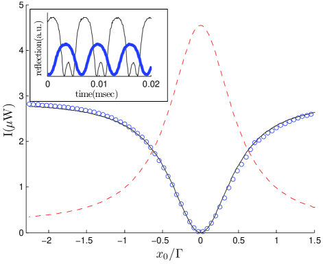
In our experiments, we tune the optical wavelength to a value at which the reflection from the cavity becomes virtually zero at the resonance, a condition known as critical coupling. In general, this critical coupling wavelength is at the edge of the Bragg region, where the FBG reflectivity changes from almost zero to almost unity. For example, the optical wavelength used for measurements of square AuPd micromechanical mirrors is . It follows that the distance between the subsequent minimums in the reflection (or, conversely, peaks in ) is , allowing us to calibrate the vertical displacement of the fiber at any temperature. A typical finesse of the cavity is between 6 and 11, i.e., . In general, each time the cavity is optically tuned by realignment of the fiber, a slightly different finesse can be expected, due to inaccuracies in the fiber positioning.
Instantaneous changes in the micromechanical beam displacement cause changes in the reflected power according to Eq. (2). The signal at the output of the photodetector can be translated into actual displacement values using the calibration discussed above. An example of the reflected optical power vs. the optical cavity detuning , together with sample time traces of mirror oscillatory movement is shown in Fig. 2. It is evident from this figure that the theory presented in Sec. III.1 provides a good analytical description of the experimental measurements of the optical cavity behavior.
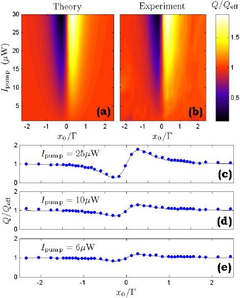
V.2 Linear damping
We begin our experimental study with investigation of what is arguably the most important prediction of the theoretical model - the possibility of a significant change in the effective dissipation in the vicinity of an optical resonance. In order to measure the effective quality factor defined in Eq. (16) at different optical powers and cavity detunings , we capacitively excite the micromechanical mirror at its apparent resonance frequency for a short period of time, and then allow the system to decay freely to the zero amplitude steady state. During this free ring down process, the slow envelope of the mechanical oscillations is measured by the means of a lock-in amplifier. The resulting slow envelope is fitted to an exponential decay function proportional to , providing an estimate of the linear dissipation constant. It is important to keep the vibration amplitude small compared to , so the nonlinearities introduced by the detection system and the optomechanical coupling [see Eqs. (15)] remain negligible.
The results presented in Fig. 3 show a good match between the experimental values of and the theoretical predictions. The measurement was done at using Sample I (see Table 1). The values of all the system parameters used in the fit are similar to those given in Sec. IV.
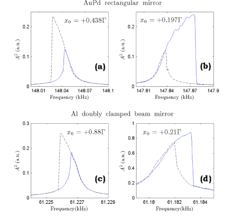
V.3 Nonlinear stiffness and damping effects
The nonlinear effects described in Eqs. (15) have been observed in all our samples. Here, we present the small amplitude frequency response of Samples II and III (see Table 1), taken at different cavity detuning values. It follows from the discussion in Sec. III.4 that the elastic nonlinearity coefficient should change sign at . Outside this region the system is expected to behave as a softening Duffing-like oscillator, while in the region around the optical resonance the behavior should be hardening. The experimental results presented in Fig. 4 confirm this prediction qualitatively.
In general, nonlinear elastic and dissipative effects in micromechanical systems can have a non negligible impact on the dynamics of these systems Nayfeh and Mook (1995); Lifshitz and Cross (2008); Almog et al. (2006, 2007); Zaitsev et al. (2011b). In the theoretical treatment in Ref. Zaitsev et al. (2011a), the nonlinear effects which do not stem from optomechanical coupling are described by the cubic nonlinearity coefficients and [see Eq. (7) in Ref. Zaitsev et al. (2011a)]. However, the experimental results show that in our samples the nonlinearities introduced by the optomechanical coupling are much stronger than any preexisting nonlinear effects, at least at relatively high optical powers. Therefore, in the present work, we have neglected all nonlinearities that do not arise due to the interaction with the optical system, i.e., and .
V.4 Self-excited oscillations
All the samples used in our experiments exhibit the phenomenon of self sustained oscillations (i.e., stable limit cycle) above certain threshold of the incident optical power. As expected, these self oscillations always occur when , i.e., in the region in which . The onset of the self oscillation can be predicted by calculating the effective linear dissipation coefficient given in Eq. (14c). Self oscillations occur when becomes negative. The amplitude and the frequency of the stable limit cycle can be found by solving Eqs. (17) and (18), respectively. A comparison between the experimentally measured self oscillation amplitudes of Sample I (see Table 1) and the corresponding solutions of Eq. (17) is shown in Fig. 5.
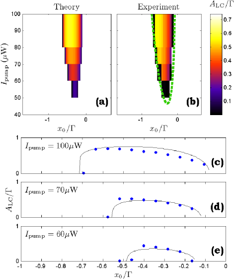
It should be emphasized that the theoretical predictions presented in Figs. 3 and 5 are both based on the same set of physical parameters presented in Sec. IV and on the mechanical properties of Sample I, given in Table 1, and differ only in the value of , which changes between different experiments, as explained above. It follows, therefore, that the theoretical model presented here can successfully describe both small vibration behavior and self oscillations with large amplitudes. The parameters extracted from experiments in one of these two modes of operation can be used to predict the dynamics of the system in the other mode.
While the theoretical fit shown in Fig. 5 is very reasonable, a hysteresis phenomenon exists in the experimental system which can not be explained by the model described above. The data presented in Fig. 5 was taken while sweeping the optical power from low to high values for a fixed value of . However, when the optical power is swept in the opposite direction, i.e., from high to low, the self oscillations disappear at lower values of . The difference in the threshold optical power can be as large as 30%. It should be mentioned that a theoretical analysis of this specific system with parameters derived in Sec. IV does not predict other stable limit cycles, although multiple stable limit cycles Hane and Suzuki (1996); Aubin et al. (2004); Metzger et al. (2008), as well as subcritical Hopf bifurcations Zaitsev et al. (2011a) are possible in systems of this type. In the system considered, the hysteresis can be possibly attributed to changes in the heating pattern and the temperature distribution in the vibrating mirror, which cannot be captured by a model with a single degree of freedom used in our analysis. A multi-mode continuum mechanics analysis of the investigated optomechanical system may provide additional insight into this hysteresis phenomenon.
It remains to determine whether the theoretical frequency shift correctly predicts the corresponding experimental results both in the case of small vibrations [see Eq. (14d)] and in the case of self-excited oscillations [see Eq. (18)]. To this end, we employ Sample II (see Table 1) and measure the spectral power density of the reflected light at the vicinity of the sample’s mechanical resonance frequency . In this experiment, the sample is not excited externally. The incident optical power is tuned so the system is expected to develop self oscillations at some region of negative optical detunings . For other values of , thermal vibrations manifest themselves as a thermal peak, whose frequency is shifted by from . By taking the spectrum traces at different values of , we are able to measure both the frequency of the small oscillations (i.e., the frequency of the thermal peak) and the self oscillation frequency.
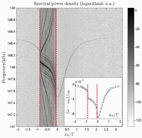
The experimental results together with a theoretical frequency shift fit are presented in Fig. 6. A very reasonable fit between theory and experiment is seen in this figure. Interestingly enough, the thermal frequency correction [see Eq. (12)] constitutes at least 98% of the frequency shift in the entire measured region.
VI Summary
In this work, we experimentally investigate the dynamics of a metallic micromechanical mirror which is one of the two mirrors that form an optical resonance cavity. The other, static mirror is implemented as a fiber Bragg grating. This unique design allows one to tune the optical cavity operating conditions to the critical coupling domain simply by controlling the wavelength of the incident light.
The finesse of our experimental optical cavities is of order ten. Therefore, all optical retardation effects can be neglected, and only thermal retardation can play a significant role in the dynamics of the micromechanical mirror. A theoretical model describing such a system was developed in Ref. Zaitsev et al. (2011a). Here, the main results are stated, both for small amplitude forced oscillations and for self sustained oscillations.
Theory predicts that coupling of the micromechanical oscillator to an optical cavity will result in changes in its effective linear dissipation, nonlinear elastic and dissipation constants, and the mechanical resonance frequency. Stable limit cycles (i.e., self sustained oscillations) will occur if the effective linear dissipation becomes negative. In addition, multiple limit cycles may be present under certain conditions. Two main optomechanical coupling mechanisms are postulated, both intermediated by heating. The first is mechanical frequency change due to heating, the other is a direct force which is a function of the temperature difference between the mirror and the environment (thermal force). The radiation pressure force is shown to be negligible in our experiments.
In the present work all the theoretical predictions mentioned above are validated by the means of micromechanical mirrors with two very different geometries (rectangular mirror with four orthogonal suspensions and a wide doubly clamped beam). The majority of the physical parameters are derived either from general considerations or independent measurements. A very reasonable quantitative agreement between the linear dissipation changes, the self oscillation amplitudes, and the frequency shifts are achieved. In addition, the theoretically predicted changes in nonlinear behavior are demonstrated for both mirror configurations.
Despite the general success of the theoretical fits of the experimental data, it is evident that a simple single degree of freedom model cannot explain some of the observed phenomena, most importantly the exact process that gives rise to the thermal force. Another unexplained phenomenon is the optical power threshold hysteresis occurring in the self oscillation measurements. Both effects can be possibly attributed to localized changes in heating and temperature distribution, and continuum mechanics approach is required in order to model them correctly.
Acknowledgments
We would like to thank O. Gottlieb for many fruitful discussions and important comments. This work is supported by the German Israel Foundation under grant 1-2038.1114.07, the Israel Science Foundation under grant 1380021, the Deborah Foundation, Eliyahu Pen Research Fund, Russell Berrie Nanotechnology Institute, the European STREP QNEMS Project and MAFAT.
References
- Braginsky and Manukin [1967] V. B. Braginsky and A. B. Manukin. Ponderomotive effects of electromagnetic radiation (in Russian). ZhETF, 52:986–989, 1967.
- Hane and Suzuki [1996] K. Hane and K. Suzuki. Self-excited vibration of a self-supporting thin film caused by laser irradiation. Sens. Actuators, A, 51:179–182, Feb 1996.
- Kimble et al. [2001] H. J. Kimble, Y. Levin, A. B. Matsko, K. S. Thorne, and S. P. Vyatchanin. Conversion of conventional gravitational-wave interferometers into quantum nondemolition interferometers by modifying their input and/or output optics. Phys. Rev. D, 65:022002, Dec 2001.
- Carmon et al. [2005] T. Carmon, H. Rokhsari, L. Yang, T. J. Kippenberg, and K. J. Vahala. Temporal behavior of radiation-pressure-induced vibrations of an optical microcavity phonon mode. Phys. Rev. Lett., 94:223902, Jun 2005.
- Arcizet et al. [2006] O. Arcizet, P.-F. Cohadon, T. Briant, M. Pinard, and A. Heidmann. Radiation-pressure cooling and optomechanical instability of a micromirror. Nature, 444:71–74, Nov 2006.
- Gigan et al. [2006] S. Gigan, H. R. Böhm, M. Paternostro, F. Blaser, G. Langer, J. B. Hertzberg, K. C. Schwab, D. B uerle, M. Aspelmeyer, and A. Zeilinger. Self-cooling of a micromirror by radiation pressure. Nature, 444:67–70, Nov 2006.
- Jayich et al. [2008] A. M. Jayich, J. C. Sankey, B. M. Zwickl, C. Yang, J. D. Thompson, S. M. Girvin, A. A. Clerk, F. Marquardt, and J. G. E. Harris. Dispersive optomechanics: a membrane inside a cavity. New J. Phys., 10:095008, Sep 2008.
- Schliesser et al. [2008] A. Schliesser, R. Riviere, G. Anetsberger, O. Arcizet, and T. J. Kippenberg. Resolved-sideband cooling of a micromechanical oscillator. Nat. Phys., 4:415–419, 2008.
- Genes et al. [2008] C. Genes, D. Vitali, P. Tombesi, S. Gigan, and M. Aspelmeyer. Ground-state cooling of a micromechanical oscillator: Comparing cold damping and cavity-assisted cooling schemes. Phys. Rev. A, 77:033804, Mar 2008.
- Kippenberg and Vahala [2008] T. J. Kippenberg and K. J. Vahala. Cavity optomechanics: Back-action at the mesoscale. Science, 321(5893):1172–1176, Aug 2008.
- Teufel et al. [2010] J. D. Teufel, D. Li, M. S. Allman, K. Cicak, A. J. Sirois, J. D. Whittaker, and R. W. Simmonds. Circuit cavity electromechanics in the strong coupling regime. arXiv, art. 1011.3067, Nov 2010.
- Wu et al. [2006] M. C. Wu, O. Solgaard, and J. E. Ford. Optical MEMS for lightwave communication. J. Lightwave Technol., 24(12):4433–4454, Dec 2006.
- Stokes et al. [1990] N. A. D. Stokes, R. M. A. Fatah, and S. Venkatesh. Self-excitation in fibre-optic microresonator sensors. Sens. Actuators, A, 21:369–372, Feb 1990.
- Lyshevski and Lyshevski [2003] S.E. Lyshevski and M.A. Lyshevski. Nano- and microoptoelectromechanical systems and nanoscale active optics. In Third IEEE Conference on Nanotechnology, 2003., volume 2, pages 840–843, Aug 2003.
- Hossein-Zadeh and Vahala [2010] M. Hossein-Zadeh and K. J. Vahala. An optomechanical oscillator on a silicon chip. IEEE J. Sel. Top. Quantum Electron., 16(1):276–287, Jan 2010.
- Metzger and Karrai [2004] C. Metzger and K. Karrai. Cavity cooling of a microlever. Nature, 432:1002–1005, Dec 2004.
- Jourdan et al. [2008] G. Jourdan, F. Comin, and J. Chevrier. Mechanical mode dependence of bolometric backaction in an atomic force microscopy microlever. Phys. Rev. Lett., 101:133904, Sep 2008.
- Metzger et al. [2008] C. Metzger, M. Ludwig, C. Neuenhahn, A. Ortlieb, I. Favero, K. Karrai, and F. Marquardt. Self-induced oscillations in an optomechanical system driven by bolometric backaction. Phys. Rev. Lett., 101:133903, Sep 2008.
- Marino and Marin [2010] F. Marino and F. Marin. Chaotically spiking attractors in suspended mirror optical cavities. arXiv, art. 1006.3509, Jun 2010.
- Ludwig et al. [2007] M. Ludwig, C. Neuenhahn, C. Metzger, A. Ortlieb, I. Favero, K. Karrai, and F. Marquardt. Self-induced oscillations in an optomechanical system. arXiv, art. 0711.2661, Nov 2007.
- Restrepo et al. [2010] J. Restrepo, J. Gabelli, C. Ciuti, and I. Favero. Classical and quantum theory of photothermal cavity cooling of a mechanical oscillator. arXiv, art. 1011.3911, Nov 2010.
- Liberato et al. [2010] S. D. Liberato, N. Lambert, and F. Nori. Quantum limit of photothermal cooling. arXiv, art. 1011.6295, Nov 2010.
- Aubin et al. [2004] K. Aubin, M. Zalalutdinov, T. Alan, R.B. Reichenbach, R. Rand, A. Zehnder, J. Parpia, and H. Craighead. Limit cycle oscillations in CW laser-driven NEMS. J. Microelectromech. Syst., 13:1018 – 1026, Dec 2004.
- Marquardt et al. [2006] F. Marquardt, J. G. E. Harris, and S. M. Girvin. Dynamical multistability induced by radiation pressure in high-finesse micromechanical optical cavities. Phys. Rev. Lett., 96:103901, Mar 2006.
- Paternostro et al. [2006] M. Paternostro, S. Gigan, M. S. Kim, F. Blaser, H. R. Böhm, and M. Aspelmeyer. Reconstructing the dynamics of a movable mirror in a detuned optical cavity. New J. Phys., 8:107, Jun 2006.
- Zaitsev et al. [2011a] S. Zaitsev, O. Gottlieb, and E. Buks. Nonlinear dynamics of a microelectromechanical mirror in an optical resonance cavity. arXiv, art. 1104.2235, Apr 2011a.
- Szemplińska-Stupnicka [1990] W. Szemplińska-Stupnicka. The Behavior of Nonlinear Vibrating Systems. Mechanics: Dynamical Systems. Kluwer Academic Publishers, Dordrecht, 1990.
- Snyder and Love [1983] A. W. Snyder and J. D. Love. Optical waveguide theory. Springer, 1983.
- Buks and Roukes [2001] E. Buks and M. L. Roukes. Metastability and the Casimir effect in micromechanical systems. Europhys. Lett., 54(2):220–226, Apr 2001.
- Mao et al. [2007] Y. Mao, S. Chang, S. Sherif, and C. Flueraru. Graded-index fiber lens proposed for ultrasmall probes used in biomedical imaging. Appl. Opt., 46:5887–5894, 2007.
- Poladian [1996] L. Poladian. Resonance mode expansions and exact solutions for nonuniform gratings. Phys. Rev. E, 54(3):2963–2975, 1996.
- Lifshitz and Cross [2008] R. Lifshitz and M.C. Cross. Nonlinear dynamics of nanomechanical and micromechanical resonators. In Heinz Georg Schuster, editor, Reviews of nonlinear dynamics and complexity, volume 1, pages 1–48. Wiley-VCH, 2008.
- Zaitsev et al. [2011b] S. Zaitsev, O. Shtempluck, E. Buks, and O. Gottlieb. Nonlinear damping in a micromechanical oscillator. Nonlin. Dyn., (in print), 2011b. arXive:0911.0833.
- Guckel et al. [1992] H. Guckel, D. Burns, C. Rutigliano, E. Lovell, and B. Choi. Diagnostic microstructures for the measurement of intrinsic strain in thin films. J. Micromech. Microeng., 2(2):86–95, 1992.
- Fang and Wickert [1994] W. Fang and J. A. Wickert. Post buckling of micromachined beams. J. Micromech. Microeng., 4:116–122, 1994.
- Fang and Wickert [1996] W. Fang and J. A. Wickert. Determining mean and gradient residual stresses in thin films using micromachined cantilevers. J. Micromech. Microeng., 6:301–309, 1996.
- Leong et al. [2008] T. G. Leong, B. R. Benson, E. K. Call, and D. H. Gracias. Thin film stress driven self-folding of microstructured containers. Small, 4(10):1605–1609, Oct 2008.
- Pandey et al. [2010] A. K. Pandey, O. Gottlieb, O. Shtempluck, and E. Buks. Performance of an AuPd micromechanical resonator as a temperature sensor. Appl. Phys. Lett., 96:203105, 2010.
- Larsen et al. [2011] T. Larsen, S. Schmid, L. Gr nberg, A. O. Niskanen, J. Hassel, S. Dohn, and A. Boisen. Ultrasensitive string-based temperature sensors. Appl. Phys. Lett., 98:121901, 2011.
- Mintz [2009] Tova Mintz. Nonlinear dynamics and stability of a microbeam array subject to parametric excitation. Master’s thesis, Technion - Israel Institute of Technology, 2009.
- Nayfeh and Mook [1995] A. H. Nayfeh and D. T. Mook. Nonlinear Oscillations. Wiley Classics Library. Wiley, New York, 1995.
- Braginsky et al. [1970] V. B. Braginsky, A. B. Manukin, and M. Yu. Tikhonov. Investigation of dissipative ponderomotive effects of electromagnetic radiation (in Russian). ZhETF, 58:1550–1555, 1970.
- Strogatz [1994] S. H. Strogatz. Nonlinear Dynamics and Chaos: with applications to physics, biology, chemistry, and engineering. Perseus Books, 1994.
- Arnold [1988] V. I. Arnold. Geometrical methods in the theory of ordinary differential equations, volume 250 of Grundlehren der mathematischen Wissenschaften. Springer-Verlag, New York, 2nd edition, 1988.
- Geballe and Giauque [1952] T. H. Geballe and W. F. Giauque. The heat capacity and entropy of gold from 15 to 300k. J. Am. Chem. Soc., 74(9):2368–2369, 1952.
- White [1953] G. K. White. The thermal conductivity of gold at low temperatures. Proc. Phys. Soc. A, 66(6):559–564, 1953.
- Veal and Rayne [1964] B. W. Veal and J. A. Rayne. Heat capacity of palladium and dilute palladium: Iron alloys from 1.4 to 100k. Phys. Rev., 135:A442 A446, 1964.
- Bennett and Ashley [1965] J. M. Bennett and E. J. Ashley. Infrared reflectance and emittance of silver and gold evaporated in ultrahigh vacuum. Appl. Opt., 2(2):221–224, 1965.
- Yu and Spicer [1968] A. Y-C. Yu and W. E. Spicer. Photoemission and optical studies of the electronic structure of palladium. Phys. Rev., 169(3):497 507, 1968.
- Almog et al. [2006] R. Almog, S. Zaitsev, O. Shtempluck, and E. Buks. High intermodulation gain in a micromechanical Duffing resonator. Appl. Phys. Lett., 88(213509), May 2006.
- Almog et al. [2007] R. Almog, S. Zaitsev, O. Shtempluck, and E. Buks. Noise squeezing in a nanomechanical Duffing resonator. Phys. Rev. Lett., 98(78103), Feb 2007.