Cross-scale coupling at a perpendicular collisionless shock
Abstract
A full particle simulation study is carried out on a perpendicular collisionless shock with a relatively low Alfven Mach number (). Recent self-consistent hybrid and full particle simulations have demonstrated ion kinetics are essential for the non-stationarity of perpendicular collisionless shocks, which means that physical processes due to ion kinetics modify the shock jump condition for fluid plasmas. This is a cross-scale coupling between fluid dynamics and ion kinetics. On the other hand, it is not easy to study cross-scale coupling of electron kinetics with ion kinetics or fluid dynamics, because it is a heavy task to conduct large-scale full particle simulations of collisionless shocks. In the present study, we have performed a two-dimensional (2D) electromagnetic full particle simulation with a “shock-rest-frame model”. The simulation domain is taken to be larger than the ion inertial length in order to include full kinetics of both electrons and ions. The present simulation result has confirmed the transition of shock structures from the cyclic self-reformation to the quasi-stationary shock front. During the transition, electrons and ions are thermalized in the direction parallel to the shock magnetic field. Ions are thermalized by low-frequency electromagnetic waves (or rippled structures) excited by strong ion temperature anisotropy at the shock foot, while electrons are thermalized by high-frequency electromagnetic waves (or whistler mode waves) excited by electron temperature anisotropy at the shock overshoot. Ion acoustic waves are also excited at the shock overshoot where the electron parallel temperature becomes higher than the ion parallel temperature. We expect that ion acoustic waves are responsible for parallel diffusion of both electrons and ions, and that a cross-scale coupling between an ion-scale mesoscopic instability and an electron-scale microscopic instability is important for structures and dynamics of a collisionless perpendicular shock.
keywords:
collisionless shock; particle-in-cell simulation; cross-scale coupling,
1 Introduction
Dynamics of shock waves in plasmas are often discussed by the shock jump conditions (Rankine-Hugoniot conditions), which describe conservation laws of mass, momentum, energy, normal magnetic field and motional electric field for fluid plasmas. On the other hand, previous kinetic simulations revealed that collisionless shocks in plasmas can be strongly non-stationary in both spatial and temporal scales of ions. In the direction normal to the shock surface of a quasi-perpendicular collisionless shock, a new shock front periodically appears (e.g., Biskamp and Welter, 1972; Quest, 1985; Lembege and Dawson, 1987; Lembege and Savoini, 1992; Hellinger et al., 2002), which is called the self-reformation. Incoming ions are reflected upstream at the shock ramp of a supercritical quasi-perpendicular collisionless shock, and they form a foot in front of the ramp during their gyration. At the upstream edge of the foot, ions are accumulated in time and are reflected upstream, which are responsible for the self-reformation. The cyclic self-reformation is due to ion dynamics, although this process has been confirmed in both electromagnetic hybrid and full particle simulations. In addition, recent full particle simulations have shown that electron-scale micro instabilities, such as Buneman instability (e.g., Shimada and Hoshino, 2000) and modified two-stream instability (e.g., Scholer et al., 2003) are excited at the foot during the cyclic self-reformation. Scholer and Matsukiyo (2004) has also demonstrated that the modified two-stream instability is also responsible for the self-reformation. Another mechanism of the self-reformation is steepening of whistler mode waves in upstream regions of oblique shocks (Krasnoselskikh et al., 2002).
In the shock-tangential direction, on the other hand, there appear fluctuations in the spatial scale of ion inertial length in the direction parallel to the shock magnetic field (Winske and Quest, 1988; Lowe and Burgess, 2003) or ion gyro radius of reflected ions in the direction perpendicular to the shock magnetic field (Burgess and Scholer, 2007), which are called the “ripples”. The compression of incoming ions at collisionless shocks results in their adiabatic heating in the shock-normal direction. In quasi-perpendicular shocks, however, the ion heating in the shock-normal direction is more dominated by the gyration of reflected ions. Thus an ion temperature anisotropy between shock-normal and shock-tangential directions becomes a common feature in the transition region of quasi-perpendicular shocks. The dynamic rippled character of the shock surface is thought to be related to the ion temperature anisotropy. Although this process has been confirmed in two-dimensional (2D) electromagnetic hybrid particle simulations, it is difficult to take into account the dynamic rippled character of the shock surface in 2D electromagnetic full particle simulations. This is because current computer resources are not necessarily enough to take such a large simulation domain of several ion inertial length.
Very recently, however, there are several attempts of 2D electromagnetic full particle simulations that take into account ion dynamics in both shock-normal and shock-surface directions (Hellinger et al. 2007; Amano and Hoshino, 2009; Lembege et al., 2009). These results indicate that ion-scale fluctuations at perpendicular collisionless shocks can dynamically change electron-scale processes such as wave excitation and electron acceleration. The purpose of this paper is to examine a cross-scale coupling between the dynamic rippled character of the shock surface and electron-scale micro instabilities. In order to take into account ion dynamics in both shock-normal and shock-surface directions, a large-scale 2D electromagnetic full particle simulation is carried out by using the “shock-rest-frame model”.
2 Full Particle Simulations
2.1 Shock-Rest-Frame Model
There are several different methods for exciting collisionless shocks in kinetic simulations of plasmas. These include the injection method (or the reflection/wall method) (e.g., Quest, 1985; Winske and Quest, 1988; Shimada and Hoshino, 2000; Hellinger et al. 2002; Lowe and Burgess, 2003; Scholer et al., 2003; Burgess and Scholer, 2007; Amano and Hoshino, 2009). the plasma release method (Ohsawa, 1985), and the magnetic piston method (e.g., Biskamp and Welter, 1972; Lembege and Dawson, 1987; Lembege and Savoini, 1992). In these methods, collisionless shocks are excited by an interaction between a supersonic plasma flow and a resting plasma. The simulation domain is taken in the downstream rest frame with the injection method, while the simulation domain is taken in the upstream rest frame withe the plasma release and magnetic piston methods. Thus an excited shock wave propagates upstream in these methods. There is also another method called the flow-flow method for exciting collisionless shocks (e.g., Omidi and Winske, 1992). Since collisionless shocks are excited by an interaction between two supersonic plasma flows in this method, there exist forward and reverse shock waves. A big problem in these methods is that excited collisionless shock waves propagate at a fast velocity, and it is necessary to take a very long simulation domain in the propagation direction of the shock waves in order to follow a long-time evolution of the shock waves. This makes it difficult to perform multidimensional simulations even with current supercomputer systems.
An alternative is to excite collisionless shocks in the shock rest frame with the “relaxation method”, whereby collisionless shocks are excited by an interaction between a supersonic plasma flow and a subsonic plasma flow moving in the same direction. This method was first used in hybrid particle simulations in 1980’s (e.g., Leroy et al., 1981, 1982), and then in full particle simulations in 1990’s (Pantellini et al., 1992; Krauss-Varban et al., 1995). This method was not so popular because of several difficulties in numerical techniques, and its application to long-term evolution of shock waves was not considered. In 2000’s, however, long-term 1D simulations with the relaxation method have been performed by using Darwin particle code (Muschietti and Lembege, 2006) and full electromagnetic particle code (Umeda and Yamazaki, 2006). Very recently, the relaxation method has also been applied to long-term 2D full electromagnetic particle simulations (Umeda et al., 2008, 2009). In general, it is not easy to perform a large-scale (ion-scale) multidimensional full electromagnetic particle simulations of collisionless shocks even with present-day supercomputers. Hence the shock-rest-frame model is important to be able to follow the evolution of shock waves for a long term with a limited computer resource.
2.2 Simulation Setup
We use a 2D full electromagnetic particle code (Umeda, 2004), in which the full set of Maxwell’s equations and the relativistic equation of motion for individual electrons and ions are solved in a self-consistent mannar. The continuity equation for charge is also solved to compute the exact current density given by the motion of charged particles (Umeda et al., 2003).
The initial state consists of two uniform regions separated by a discontinuity. In the upstream region that is taken in the left hand side of the simulation domain, electrons and ions are distributed uniformly in space and are given random velocities to approximate shifted Maxwellian momentum distributions with the drift velocity , number density , isotropic temperatures and , where , , and are the mass, charge, plasma frequency and thermal velocity, respectively. Subscripts “1” and “2” denote “upstream” and “downstream”, respectively. The upstream magnetic field is also assumed to be uniform, where is the cyclotron frequency (with sign included). The downstream region taken in the right-hand side of the simulation domain is prepared similarly with the drift velocity , density , isotropic temperatures and , and magnetic field .
We take the simulation domain in the - plane and assume a perpendicular shock (i.e., ). Since the ambient magnetic field is taken in the direction, free motion of particles along the ambient magnetic field is taken into account. As a motional electric field, a uniform external electric field is applied in both upstream and downstream regions, so that both electrons and ions drift in the direction. At the left boundary of the simulation domain in the direction, we inject plasmas with the same quantities as those in the upstream region, while plasmas with the same quantities as those in the downstream region are also injected from the right boundary in the direction. We adopted absorbing boundaries to suppress non-physical reflection of electromagnetic waves at both ends of simulation domain in the direction (Umeda et al., 2001), while the periodic boundaries are imposed in the direction.
In the relaxation method, the initial condition is given by solving the shock jump conditions (Rankine-Hugoniot conditions) for a magnetized two-fluid isotropic plasma consisting of electrons and ions (Hudson, 1970). In order to determine a unique initial downstream state, we need given upstream quantities , , , , and and an additional parameter. We assume a low-beta and weakly-magnetized plasma such that and in the upstream region. We also use a reduced ion-to-electron mass ratio for computational efficiency. The light speed and the bulk flow velocity of the upstream plasma are also assumed. Then, the Alfvén Mach number is calculated as . The ion-to-electron temperature ratio in the upstream region is given as . In this study, downstream ion-to-electron temperature ratio is also assumed as another initial parameter to obtain the unique downstream quantities by solving the shock jump conditions, , , , and .
In this study, we perform two runs with different sizes of the simulation domain. We use cells for the upstream region and cells for the downstream region, respectively, in Run A. The grid spacing and time step of the present simulation are and , respectively. Here is the electron Debye length upstream. Thus the total size of the simulation domain is which is long enough to include the ion-scale rippled structure, where is the ion inertial length. In Run B, we use cells for the upstream region and cells for the downstream region, respectively. Thus the the total size of the simulation domain is , in which ion-scale processes along the ambient magnetic field is neglected. We used 16 pairs of electrons and ions per cell in the upstream region and 64 pairs of electrons and ions per cell in the downstream region, respectively, at the initial state.
3 Results
Figure 1 shows the tangential component of magnetic field as a function of position and time for Runs A and B. The position and time are renormalized by the ion inertial length and the ion cyclotron angular period , respectively. The magnitude is normalized by the initial upstream magnetic field . In Fig.1, the tangential magnetic fields are averaged over the direction, which means that fluctuations in the shock-tangential direction are neglected.
In the present shock-rest-frame model, a shock wave is excited by the relaxation of the two plasmas with different quantities. Since the initial state is given by the shock jump conditions for a “two-fluid” plasma consisting of electrons and ions, the kinetic effect is excluded in the initial state and the excited shock becomes “almost” at rest in the simulation domain. In both runs, the shock front appears and disappears on a timescale of the downstream ion gyro period, which corresponds to the cyclic self-reformation of a perpendicular shock. The reformation takes place for more than in Run B, while the reformation seems to be less significant after in Run A. The previous 2D full particle simulations have demonstrated the transition from the cyclic self-reformation to a “quasi-stationary” shock front (Hellinger et al., 2007; Lembege et al., 2009), which is in agreement with Run A. However, it should be noted that the self-reformation does take place even after in Run A, but on a different timescale, when we focus on a local tangential magnetic field.
When the length of the simulation domain in the shock-tangential direction is shorter than the ion inertial length, ion-scale fluctuations along the shock surface (ripples) do not appear and the profiles of electromagnetic fields become almost one-dimensional (Umeda et al., 2008, 2009), and there exists apparent cyclic self-reformation of the perpendicular shock as seen in Run B. The present result suggests that the ion-scale fluctuations in the shock-tangential direction play an important role in the sequential appearance of non-stationary and quasi-stationary shock fronts.
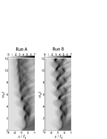
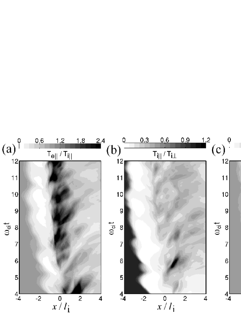
Figure 2 shows the electron and ion temperatures as a function of position and time for Run A. The panels (a), (b) and (c) corresponds to the temperature ratios , and , respectively. The panels (d) and (e) corresponds to the parallel temperatures of electrons and ions, and , respectively. Note that these temperatures are averaged over the direction, and that the parallel temperatures are approximated by the temperatures in the direction while the perpendicular temperatures are approximated by the average of temperatures in the and directions.
From , the electron temperature in the direction parallel to the ambient magnetic field, , at the shock overshoot becomes twice as large as the ion parallel temperature, . At the shock foot, the electron perpendicular temperature, , is higher than the electron parallel temperature, . On the other hand, becomes higher than at the shock overshoot. In the downstream region, is slightly higher than . As seen in Fig.2d, electrons are strongly thermalized in the direction parallel to the shock magnetic field at the overshoot, suggesting that there exists a strong parallel diffusion process at the overshoot from . On the other hand, ion parallel temperature becomes higher at the shock foot and in the downstream region as seen in Fig.2e. Fig.2 shows that electrons and ions are thermalized in different regions, suggesting that electrons and ions heating takes place on different scales.
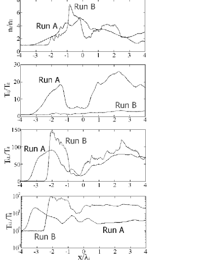
Figure 3 shows snapshots of shock magnetic field , ion density , ion parallel temperature , ion parallel temperature , and ion temperature ratio . at for Runs A and B. Although the Mach number of the present simulation run is relatively low (), the present perpendicular shock is supercritical, and therefore the cyclotron motion of reflected ions is dominant for ion heating in the shock-normal direction. At the shock overshoot, the ion parallel and perpendicular temperatures are low because of the accumulation of upstream cold ions. The ion perpendicular temperature becomes higher at the shock foot because of the non-gyrotropic velocity distribution of reflected ions. At the shock foot, ions are also thermalized in the parallel direction because of an anisotropy-driven ion cyclotron wave in Run A. However, the ion parallel heating is not responsible for the electron parallel heating (see Fig.2). As seen in Fig.3, the ion temperature anisotropy () would be a common feature at perpendicular collisionless shocks. In Run B, there is no ion parallel heating because the system length does not allow the existence of an ion cyclotron wave in the parallel direction. Thus the temperature anisotropy becomes much higher than in Run A.
In order to study mechanisms for parallel heating of electrons and ions, we take Fourier transformation of the shock-normal magnetic field component and the shock-tangential electric field component in the transition region. Figure 4 shows frequency-wavenumber spectra of the shock-normal magnetic field component for different time intervals: (a), (b), (c), and (d). The frequency and wavenumber are normalized by and , respectively. These frequency-wavenumber spectra are obtained by projection of spectra onto the plane. Note that the typical electron and ion cyclotron frequencies in the transition region are and , respectively, and their maximum values are and , respectively, at the overshoot.
In Fig.4, we found a strong enhancement of component below , which might correspond to the rippled structures due to the ion temperature anisotropy. We also found an enhancement of component over , suggesting that electromagnetic electron cyclotron waves are excited in the transition region, which might correspond to the “nonlinear whistler waves” reported by Hellinger et al. (2007) and Lembege et al. (2009).
For the high-frequency electromagnetic electron cyclotron waves are enhanced over , while other time intervals the component is enhanced up to , implying that the high-frequency waves are responsible for the parallel heating of electrons at (Fig.2a and 2d). Note that excitation of electromagnetic whistler mode waves due to electron temperature anisotropy are observed in the previous 2D simulations of perpendicular shocks (Umeda et al., 2008). Since the electron parallel temperature becomes higher than the electron perpendicular temperature for , whistler mode waves due to electron temperature anisotropy.
Ions are thermalized in the direction parallel to the shock magnetic field by the low-frequency electromagnetic waves below . However, these waves are not so much responsible for the parallel heating of electrons, because there is not significant parallel heating of electrons at the shock foot as seen in Fig.2d.
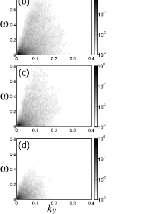
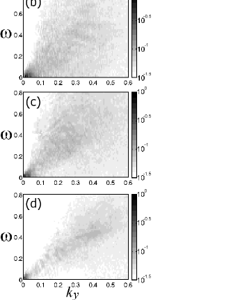
Figure 5 shows frequency-wavenumber spectra of the shock-normal magnetic field component in the transition region for different time intervals: (a), (b), (c), and (d). with the same format as Fig.4. The typical ion plasma frequency in the transition region is , and its maximum value is at the overshoot.
For , we found a strong enhancement of the component up to , while there is not any enhancement in a high-frequency range for . The phase velocity of these wave are estimated as . From Fig.2, the typical parallel temperatures of electrons and ions are estimated as and . Thus the ion acoustic velocity is obtained as
| (1) |
with , suggesting that the ion acoustic waves are excited in the transition region. As shown in Fig.2a, the electron parallel temperature becomes higher than the ion parallel temperature due to electron cyclotron waves at the shock overshoot, which is a suitable condition for excitation of ion acoustic waves.
Figs.4 and 5 show active wave phenomena in the transition region, although the shock front appears to be “quasi-stationary” when averaged over the direction. The shock front becomes turbulent instead of quasi-stationary. We expect that the ion acoustic waves would play a role in the transition process from the self-reformation phase to the turbulent phase, because ion acoustic waves are responsible for diffusion of both electrons and ions along a magnetic field.
4 Summary
We performed a 2D electromagnetic full particle simulation of a low-Mach-number perpendicular collisionless shock. The results are itemized below.
-
1.
It has been confirmed that the cyclic self-reformation of the shock front becomes less significant as time elapses, which is consistent with the previous 2D simulations (Hellinger et al., 2007; Lembege et al., 2009). The shock front appears to be “quasi-stationary” by averaging the spatial profiles of electromagnetic fields over the shock-tangential direction, although electron-scale microscopic and ion-scale mesoscopic instabilities are quite dynamic and the shock front becomes turbulent.
-
2.
During the transition from the cyclic self-reformation to the turbulent shock front, electrons and ions are thermalized in the direction parallel to the shock magnetic field in different regions and by different mechanisms. The electron parallel temperature is more enhanced than the parallel ion temperature at the shock overshoot.
-
3.
Low-frequency electromagnetic (ion cyclotron or mirror mode) waves are excited at the shock foot, which corresponds to the rippled structure in the shock-tangential direction. These waves are excited by the strong temperature anisotropy of ions. Ions are thermalized in the direction parallel to the shock magnetic field by these waves, but electrons are not.
-
4.
Electromagnetic electron cyclotron (whistler mode) waves are excited at the shock overshoot. These waves are excited by the temperature anisotropy of electrons. Electrons are thermalized in the direction parallel to the shock magnetic field by these waves, but ions are not.
-
5.
Strong parallel heating of electrons at the shock overshoot results in the suitable condition for excitation of ion acoustic waves. The rippled structure might be an energy source of the ion acoustic waves. However, their detailed excitation mechanism is not yet clear. The ion acoustic waves are responsible for parallel diffusion of both electrons and ions. We expect that the ion acoustic waves have a direct implication with the transition from the self-reformation phase to the turbulent phase.
-
6.
A cross-scale coupling between an ion-scale mesoscopic instability and an electron-scale microscopic instability is important for structures and dynamics of collisionless perpendicular shocks. Hence large-scale full kinetic simulations are quite important.
It is noted that Yuan et al. (2009) have demonstrated the cyclic self-reformation in their 2D hybrid simulation of a quasi-perpendicular shock with , which is different from the results in purely perpendicular shocks. We are now trying to check whether the reformation is suppressed or not at a oblique shock by a large-scale 2D PIC simulation. However, this is beyond the scope of the present paper.
Finally, the effect of mass ratio is discussed. In the present simulation parameter (), electron cyclotron (Bernstein) modes is weakly unstable due to current driven instability with a reduced mass ratio (e.g., Muschietti and Lembege, 2006). When we use the real mass ratio of , the thermal velocity of upstream electrons becomes about 8.6 times as large as the case of , and the electron cyclotron modes are stabilized. In contrast with current driven instability, obliquely propagating whistler mode waves becomes unstable due to modified two-stream instability (Matsukiyo and Scholer, 2003, 2006). However, the evolution of modified two-stream instability at perpendicular shocks has been studied only in a localized uniform model (Matsukiyo and Scholer, 2006). The influences of modified two-stream instability on the reformation process of perpendicular shocks is an outstanding issue to be addressed by future 2D PIC simulations of perpendicular collisionless shocks.
References
- [1] Amano, T., Hoshino, M., 2009. Electron shock surfing acceleration in multidimensions: Two-dimensional particle-in-cell simulation of collisionless perpendicular shock, Astrophys. J. 690, 244–251.
- [2] Biskamp, D., Welter, H., 1972. Numerical studies of magnetosonic collisionless shock waves, Nuclear Fusion 12, 663–666.
- [3] Burgess, D., Scholer, M., 2007. Shock front instability associated with reflected ions at the perpendicular shock, Phys. Plasmas 14, 012108, doi:10.1063/1.2435317.
- [4] Hellinger, P., Travnicek, P. M., Lembege, B., Savoini, P., 2007. Emission of nonlinear whistler waves at the front of perpendicular supercritical shocks: hybrid versus particle simulations, Geophys. Res. Lett. 34, L14109, doi:10.1029/2007GL030239.
- [5] Hellinger, P., Travnicek, P., Matsumoto, H., 2002. Reformation of perpendicular shocks: Hybrid simulations, Geophys. Res. Lett. 29, 2234, doi:10.1029/2002GL015915.
- [6] Hudson, P. D., 1970. Discontinuities in an anisotropic plasma and their identification in the solar wind, Planet. Space Sci. 18, 1611–1622.
- [7] Krasnoselskikh, V. V., Lembege, B., Savoini, P., Lobzin, V. V., 2002, Nonstationarity of strong collisionless quasiperpendicular shocks: Theory and full particle numerical simulations, Phys. Plasmas, 9, 1192–1209.
- [8] Krauss-Varban, D., Pantellini, F. G. E., Burgess, D., 1995. Electron dynamics and whistler waves at quasi-perpendicular shocks, Geophys. Res. Lett. 22, 2091–2094.
- [9] Lembege, B., Dawson, J. M., 1987. Self-consistent study of a perpendicular collisionless and nonresistive shock, Phys. Fluids 30, 1767–1788.
- [10] Lembege, B., Savoini, P., 1992. Non-stationarity of a two-dimensional quasi-perpendicular supercritical collisionless shock by self-reformation, Phys. Fluids B 4, 3533–3548.
- [11] Lembege, B., Savoini, P., Hellinger, P., Travnicek, P. M., 2009. Nonstationarity of a two-dimensional perpendicular shock: Competing mechanism, J. Geophys. Res. 114, A03217, doi:10.1029/2008JA013618.
- [12] Leroy, M. M., Goodrich, C. C., Winske, D., Wu, C. S., Papadopoulos, K., 1981. Simulation of a perpendicular bow shock, Geophys. Res. Lett. 8, 1269–1272.
- [13] Leroy, M. M., Winske, D., Goodrich, C. C., Wu, C. S., Papadopoulos, K., 1982. The structure of perpendicular bow shocks, J. Geophys. Res. 87, 5081–5094.
- [14] Lowe, R. E., Burgess, D., 2003. The properties and causes of rippling in quasi-perpendicular collisionless shock fronts, Ann. Geophys. 21, 671–679.
- [15] Matsukiyo, S., Scholer, M., 2003. Modified two-stream instability in the foot of high Mach number quasi-perpendicular shocks, J. Geophys. Res. 108, 1459, doi:10.1029/2003JA010080.
- [16] Matsukiyo, S., Scholer, M., 2006. On microinstabilities in the foot of high Mach number perpendicular shocks, J. Geophys. Res. 111, A06104, doi:10.1029/2005JA011409.
- [17] Muschietti, L., Lembege, B., 2006. Electron cyclotron microinstability in the foot of a perpendicular shock: A self-consistent PIC simulation, Adv. Space Res. 37, 483–493.
- [18] Ohsawa, Y., 1985. Strong ion acceleration by a collisionless magnetosonic shock wave propagating perpendicularly to a magnetic field Phys. Fluids 28, 2130–2136.
- [19] Omidi, N., Winske, D., 1992. Kinetic structure of slow shocks: Effects of the electromagnetic ion/ion cyclotron instability, J. Geophys. Res. 97, 14,801–14,821.
- [20] Pantellini, F. G. E., Heron, A., Adam, J. C., Mangeney, A., 1992. The role of the whistler precursor during the cyclic reformation of a quasi-parallel shock, J. Geophys. Res. 97, 1303–1311.
- [21] Quest, K. B., 1985. Simulations of high-Mach-number collisionless perpendicular shocks in astrophysical plasmas, Phys. Rev. Lett. 54, 1872–1874.
- [22] Scholer, M., Shinohara, I., Matsukiyo, S., 2003. Quasi-perpendicular shocks: length scale of the cross-shock potential, shock reformation, and implication for shock surfing. J. Geophys. Res. 108, 1014, doi:10.1029/2002JA009515.
- [23] Scholer, M., Matsukiyo, S., 2004. Nonstationarity of quasi-perpendicular shocks: a comparison of full particle simulations with different ion to electron mass ratio, Ann. Geophys. 22, 2345–2353.
- [24] Shimada, N., Hoshino, M., 2000. Strong electron acceleration at high Mach number shock waves: Simulation study of electron dynamics, Astrophys. J. 543, L67–L71.
- [25] Umeda, T., 2004. Study on nonlinear processes of electron beam instabilities via computer simulations, Ph.D. Thesis, Kyoto University.
- [26] Umeda, T., Omura, Y., Matsumoto, H., 2001. An improved masking method for absorbing boundaries in electromagnetic particle simulations, Comput. Phys. Commun. 137, 286–299.
- [27] Umeda, T., Omura, Y., Tominaga, T., Matsumoto, H., 2003. A new charge conservation method in electromagnetic particle simulations, Comput. Phys. Commun. 156, 73–85.
- [28] Umeda, T., Yamao, M., Yamazaki, R., 2008. Two-dimensional full particle simulation of a perpendicular collisionless shock with a shock-rest-frame model, Astrophys. J. 681, L85–L88.
- [29] Umeda, T., Yamao, M., Yamazaki, R., 2009. Electron acceleration at a low-Mach-number perpendicular collisionless shock, Astrophys. J. 695, 574–579.
- [30] Umeda, T., Yamazaki, R., 2006. Particle simulation of a perpendicular collisionless shock: A shock-rest-frame model, Earth Planets Space 58, e41–e44.
- [31] Yuan, X., Cairns, I. H., Trichtchenko, L., Rankin R., Danskin, D. W., 2009. Confirmation of quasi-perpendicular shock reformation in two-dimensional hybrid simulations, Geophys. Res. Lett. 36, L05103, doi:10.1029/2008GL036675.
- [32] Winske, D., Quest, K. B., 1988. Magnetic-field and density-fluctuations at perpendicular supercritical collisionless shocks, J. Geophys. Res. 93, 9681–9693.