Multifaceted Faculty Network Design and Management: Practice and Experience Report 111A short version was presented at C3S2E 2011.
Abstract
We report on our experience on multidimensional aspects of our
faculty’s network design and management, including some unique aspects such
as campus-wide VLANs and ghosting, security and monitoring, switching and routing,
and others. We outline a historical perspective on certain research,
design, and development decisions and discuss the network topology, its scalability,
and management in detail; the services our network provides, and its evolution.
We overview the security aspects of the management as well
as data management and automation and the use of the data by other
members of the IT group in the faculty.
Keywords: network topology, spanning tree, network security, network management, VLANs
0.1 Introduction
We present a number of the aspects we designed in the network infrastructure at the Faculty of Engineering and Computer Science (ENCS), Concordia University, Montreal, Quebec, Canada. The experience report covers about 10 years of design, development, deployment, and change management 2001–2010. We first very briefly touch on some historical notes necessitating the presented design and its evolution. Then we highlight the key problems and motivation in Section 0.1.2 and proposed solutions to those problems in Section 0.1.3.
0.1.1 Brief historical notes
We are reporting on the evolution of a functioning network as it grew through ad hoc responses to problems over more than ten years, not on a careful design of a freshly implemented network. When the IT personnel under various departments such as CSE, ECE, MIE, BCEE, etc. were merged under the umbrella of the Faculty of ENCS, the smaller departmental networks and their management infrastructure had to be streamlined. These mergers saw the network grow approximately 4-fold (this represents about of the entire University’s network). New policies, management strategies, security considerations, reliability, and scalability had to be addressed, especially, since, at the time of the merger the networks were spanning more than 10 geographically distributed buildings. The present network is comprised of approximately 4800 network clients that include desktops, servers, and other networked devices.
0.1.2 Problems and challenges
As we report on an evolutionary process, with motivation for change sometimes being political (as in the case of integrating multiple departments), sometimes technical (as in the case of needing to run multiple simultaneous ghosting sessions without disturbing the global network), and sometimes managerial (as in the case of our need for a network database to track locations of equipment in near-real time). As a result, several key issues emerged:
-
•
Security.
-
•
Scalability and management.
-
•
Accretion of multiple departments with different setups.
-
•
Trusted subnets (analyst-managed) and untrusted subnets (user-managed).
-
•
Ghosting (OS image cloning).
-
•
Cooperation with other IT subgroups.
-
•
Connectivity and reliability.
0.1.3 Proposed solutions
The solutions deployed to address the challenges are summarised here:
-
•
Campus-wide VLANs. The novelty in our design in here included, which nobody else to our knowledge had ghosting VLANs capable of “imitating” the global network in multicast sessions without adversely affecting normal operations.
-
•
Extensive scripting and database support for management and monitoring.
-
•
Spanning tree setup.
-
•
Development of a set of audited tools and shells to allow sister group to access the data and perform simple networking tasks.
-
•
Extensive internal and external firewall design.
0.1.4 Organisation
What follows are some details on the solutions, best practices, new challenges and future work. In Section 0.2.3 the ideas and their realization are described behind the notion of campus-wide VLANs. In Section 0.5 we describe security aspects of the network design and our conservative approach which allows for more flexibility. In Section 0.2 are some switchfarm deployment details, whose configuration allows for spanning tree to function. In Section 0.3 are the design considerations of our routing setup taking into consideration the security and campus-wide-VLAN aspects. In Section 0.4 we describe the type of services we provide with our network to our faculty’s community. We provide some concluding remarks and statistical summary in Section 0.7.
0.2 Switching
We describe some our switching topology and configuration details to highlight key points of interest.
0.2.1 Configuration
We maintain a common central switch configuration profile, which is used when deploying a new switch. In that profile, we typically configure the DNS settings, switch logging, and NTP hosts (for automation and monitoring of switch logs). Standard procedures are in place for switch additions, removals, moves, etc. as far as the configuration is concerned, and allowing the spanning tree protocol to function properly.
0.2.2 Spanning tree protocol
Following the mathematical notion of spanning tree (connected undirected graph), the corresponding switching protocol [20, 38, 8] (STP) is fully implemented in our network that covers pretty much the entire switch farm. We have a single spanning tree covering all our switches, that facilitates failover as well as redundancy. The main point of the protocol is to have connectivity coverage to all the leaf nodes without creating an accidental loop directly or indirectly “shortcircuiting” any two or more switch ports followed by the shutdown of the tree. To keep it simpler, we don’t have a mesh of switches, but we make the extensive use of port channels to maintain redundancy and most of our VLANs are trunked on all switches. Tree structure of a connected element is a triangle (with one “corner” “broken”, so it is still an acyclic graph). One of the “access” switches in the triangle is connected to another to form a pair via a gigabit port (via GBICs), and other ports of the corresponding switches go to the core stack described below with one of the ports configured to be in blocking mode to prevent looping. Breaking any of the links would not result in a loss of connectivity as the redundant path would be followed.
Two major buildings have a stack of Cisco Catalyst 3750 switches. The main one, is the 9-element stack of BigSwitch1, is now arranged in a ring (see Figure 1).
    1 -- 2 -- 4 -- 6
    |              |
    3 -- 5 -- 7    8
                \  |
                 \ |
                   9
Elements in the upper row are powered by one UPS, and elements in the lower row (and 9) are powered by another. We have taken care to connect all the spanning-tree-paired switches to corresponding port numbers on vertically matched stack elements; e.g., a switch (1/0/15) (stack element 1, port 15) is connected to another switch (3/0/15), and a switch (2/0/9) is connected to another (5/0/9). That way, even if we lose a UPS in Room A, we still have full switch connectivity. To elaborate, an access switch in wiring closet is connected through one of its gigabit ports, say, to stack element 1, port 15; its other gigabit port is connected to its “closet-mate” , which is itself connected to stack element 3, port 15, thus forming a three point loop for the spanning tree protocol to handle. In normal operation, spanning tree will very quickly decide to block the direct connection between and , sending all traffic through the core stack. If either uplink to the core stack is lost, or if one of the stack elements 1 or 3 is lost, spanning tree will quickly unblock the link, reestablishing full connectivity. If one of the UPSes in the network operations center should fail, Figure 1 shows that only one of the stack elements 1 and 3 will be lost, and once again, spanning tree will quickly unblock the link, reestablishing full connectivity.
When connecting a non-switch device such as a server, we leave its “paired port” empty, but we preconfigure it so that the device’s cable can just be moved to the paired port. For the partnerless switches we give double uplinks to both paired ports. Switch #9 is a spare. If switch #n fails, #9 can be reconfigured to take over from it. The schematic of the described connectivity is illustrated in Figure 2 (current configuration) where BigSwitch1 and BigSwitch2 comprise the “Central stack A” and “B”.


0.2.3 Campus-wide VLANs
We diverge from the classical Cisco network setup [10], where the backbone of the network consists of the core switches connected to distribution and access switches per floor with access switches for individual end nodes (computers, etc.). This would inhibit our current design’s ability to setup any computer on any VLAN anywhere on campus instantly. This is where our innovation comes in. When we look at the standard Cisco network setup, we could see that our configuration draws some similarities. These similarities can be seen if we look at the upstream provider for our network’s connectivity as the core network. Then, our core BigSwitch1 and BigSwitch2 switch stacks (that correspond to the knots in Figure 10) as well as the smaller gigabit switches act as distribution switches, and the spanning-tree-paired switches would play the role of the access switches.
Initially, we have not implemented Layer 3 connectivity on our switchfarm opting instead to have the routing and firewalling along with NATing performed by a redundant set of Linux boxes (one in each building via the core fibre-interconnected switches, see Figure 2). This design was chosen because of constraints imposed by the ghosting requirement (“ghosting” as in cloning desktop operating systems’ images using the Symantec’s Ghost software that allows multicast distribution of the disk images to multiple clients simultaneously) as well as the need for geographically dispersed VLANs for faculty members.
Multiple ghosting sessions.
The Desktop group for some duration of time was performing 10 simultaneous ghosting sessions across analyst-managed computers primarily spread across two buildings (earlier there were more buildings to cover before the Faculty got consolidated). A single person was able to ghost a floor of computers at a time. The entire ghosting season would last 3-5 days to cover the majority of the lab computers. The ghost image sizes varied for 10GB for a Linux partition and about 20GB for a Windows partition. To accomplish such a feat without significant interruption of the network service to the rest of the regular users during the ghosting season the Desktop group required a network service that could support all this. One way to do this was allocating a VLAN per Desktop group member, where each Desktop member also has their own ghosting server – two ghosting servers did not play well together in the same VLAN – as well as a ghost router, which is a copy of one of our main router pairs along with the DHCP server copy to work in the ghost VLANs. In order to ghost any arbitrary number of computers normally residing in their respective VLANs and potentially across buildings, a Desktop group member would move the switch ports of all those machines (via the scripting and shell services we implemented in-house, see Section 0.6.2) to their own ghosting VLAN in batch, and can do the entire ghosting session of this arbitrary set of machines without disruption to the main networking services anywhere else in the Faculty.
Custom VLANs for faculty members.
To secure and seclude research groups or individual Faculty members for the computers they purchase for them, their students and affiliates to do the research, share files, etc. they are usually allocated a VLAN and a subnet of a required size depending on their needs. This isolates them from potential attacks from other groups and subnets while permitting network printing and file sharing they need. It also happens in some cases some professors or research groups span their presence across buildings as well necessitating the VLANs being available anywhere on the campus at any point in time.
0.3 Routing
This report covers essentially the modus operandi between circa 2001 to 2010, where all our switchfarm was Layer-2 only. The routing, as a result, has been performed on pairs of redundant Linux boxes geographically spread across buildings, and is comprised of an internal pair (among our own subnetworks) and an external pair (the edge to the outside). The routers impose the firewall rules designed for different purposes (see Section 0.5.1). The routing supports all the required virtual interfaces for the VLANs present on the network and the maintenance of the routing tables.
Connection tracking.
The routers employ connection tracking for failover between buildings without loss of sessions where the corresponding tables are saved and reloaded from one end (primary) to another (secondary) in case of a failure of the primary or reboot of the primary, automatically.
0.4 Services
Our network design, besides providing the usual “access to the Internet” is geared towards services for the students, Faculty and staff. There are all kinds of specialised needs for printing, filer sharing, servers, research equipment and groups including research graphics cluster, as well as other research clusters in parallel computing, software security, service-oriented architectures, language engineering, networking research, database engineering, genomics, audio-visual, pattern recognition, and others.
The services to our own IT subgroups are provided in the form of the network database data IT staff require for their daily activities. The data are provided via access tools (see Section 0.6.2), which enable IT staff to perform a restricted set of networking tasks in order to improve our scalability as an IT group.
AL.
A now historical service to support authenticated laptop (AL) connections by the users with a valid account in the Faculty and a dynamic IP within a range set aside for AL. AL was an important service to our clientele. While it has significant security considerations, as nearly any our service does, but AL is a service more than a security problem. Most of the switch ports were configured with dot1x, so potentially any unused patched jack would be in the AL state so a potential user could use it to authenticate themselves to be allowed to connect further. At the present, AL replaced by the allocation of static IP addresses on our network to the users that make a proper request and are not using wireless connections. The replacement was necessitated by the decision of the parent IT unit to abandon the use of proprietary software for Windows platforms since that platform does not have a native implementation of two-factor 802.1X authentication built-in at the time of this writing, and the proprietary software licensing terms became unbearable. While the AL service could still support Linux and MacOS X clients, their number, while increasing, is still small comparative to the Windows clients.
0.5 Security
In the AITS group, IT security spans aspects covering several subgroups besides networking, including system administration, desktop operations, faculty information systems, and user services. Our responsibly is to ensure a sane and secure networking environment to the entire Faculty and guard the integrity and availability of our backbone core and the leaf nodes [2, 3, 15, 24].
This covers the network bandwidth monitoring, health of the switch farm, routing equipment, and rogue DHCP servers monitoring as well as desktop monitoring for infections and vulnerabilities (with quarantine), potential violations by MAC spoofing attacks, port scanning, illegal peer-to-peer activities, and equipment moves.
0.5.1 Firewalls
We employ two pairs of redundant firewalls across two buildings implemented using iptables in Scientific Linux environment [23, 21, 33] that provide a number of internal and external services, routing, NATing, logging and monitoring. Both firewalls total in more than 1000 rules. Both firewalls employ conservative deny-all policy and allow only required services.
Why Scientific Linux and iptables? While any Linux distribution would be fine, we traditionally used RedHat derivatives such as RHEL, Fedora, and now Scientific Linux as it is a widely deployed and entreprise level operating system. The primary justification for iptables (aside from the cost and being one of the most widely deployed industry standard firewalls) is that iptables allows unrestricted branching of the rule “tree”, something that’s important to the task of securely managing traffic amongst more than 150 subnets offering different services and presenting widely varying security problems. Cisco ACLs e.g. are simply not up to the task. Additionally, when we started, Cisco ASA didn’t exist, but ipchains (precursor of iptables) did. Moreover, cost was an issue. A “layer 2” Cisco network with “layer 3” handled by commodity hardware and free and open-source software was at the same time much cheaper and more flexible than any available alternative.
The internal firewall provides or denies access to or from our IT’s core servers managed by the system administration group and desktop groups to allow printing, connectivity to the NetApp filers, web applications and the like. Misbehaving hosts are also placed in quarantine on the internal firewall (e.g. in Figure 5 what we configure to place on quarantine and the resulting iptables rules are in Figure 6 compiled with a make [30] marking at pre-routing with a special token; and anything marked with that token at the forward chain is only allowed accessing permitted patch and antivirus sites).
...
# admnusr 2010-11-03 XXX.XXX.XXX.134 8 OS[Windows 5.1] MS06-040 VULNERABLE
sickhost.domain
...
Chain PREROUTING (policy ACCEPT)
target      prot opt source          destination
MARK        all  --  sickhost.domain anywhere        MARK set 0x2
...
Chain FORWARD (policy ACCEPT)
target      prot opt source          destination
qrntine     all  --  anywhere        anywhere        MARK match 0x2
...
Chain qrntine (1 references)
target      prot opt source          destination
ACCEPT      all  --  anywhere        XXX.XXX.XXX.0/24
ACCEPT      all  --  anywhere        anywhere
ACCEPT      tcp  --  anywhere        antivirus-site1.domain tcp dpt:1234
ACCEPT      tcp  --  anywhere        antivirus-site1.domain tcp dpt:1234
patchSites  all  --  anywhere        anywhere
REJECT      tcp  --  anywhere        anywhere        reject-with tcp-reset
REJECT      all  --  anywhere        anywhere        reject-with icmp-port-unreachable
The external firewall deals with the connectivity to and from outside of our administrative domain allowing certain incoming connections such as web, ssh, remote desktop, licensing, and printing services from the University’s wireless, and the like to an authorised list of hosts. Offending phishing and other external sites are blocked at this firewall. NATing from the private space as well as bandwidth restriction enforcement take place here as well.
The list of blocked internal machines and external sites are provided via a web page to the rest of IT staff, primarily the service desk to help to deal with phishing attacks and the related inquiries.
The rules are processed from a source script by a bash script in order to prepare an iptables-restore loadable file that pre-resolves the DNS entries to speed up processing and deter errors as well as loads the rulesets automically to avoid race conditions, etc. – in an approach that was similarly presented in [27].
0.5.2 Switch port violations
We also monitor switch port violations (swpvios). Most of the ports are configured to be bound to a fixed number of known MAC addresses (usually one). When users attempt to move computers around or plug-in an unknown piece of networked equipment into a registered jack we received an alert and are notified of its location. Ports were bound to MAC addresses in order to prevent students or passers-by from unplugging our computers and plugging in their own. Not doing this would be a failure waiting to happen (see on MAC address spoofing detection in Section 0.5.3).
A sample of a common switch port configuration in teaching and research labs is in Figure 7.
We used to shutdown ports automatically, requiring a manual intervention to bring them back up by an analyst as a proactive way to shut out rogue clients, but it became evident fast enough that this induced a significant manual intervention overhead as most frequent violations were people moving their computers from one desk to another, or someone connecting their laptop from jack to jack in a room until they realised it’s not going to work. The switch ports are configured to restrict. The users do not get the network service until they talk to us or to the service desk to notify of the fact that the equipment has moved or new equipment was purchased and requires networking. Switching ports to protect does silence the repeated alerts without granting the network service until the computer is moved back to its original jack or we are notified to authorise the move. It’s worth noting protect has appeared with a particular release of IOS, and prior to that shutdown was the only option (needless to say the scale of manual intervention overhead required to bring the ports back up). Additionally, while restrict is a useful macro, it has a side effect of complicating debugging when machines move by necessitating port clear-ups from “sticky” MAC addresses. In the end, the user services staff have been granted access to that feature via a shell to clear up ports, etc. to address the management scalability problem.
interface FastEthernet0/40
 description [Auto] machine.domain
 switchport access vlan XYZ
 switchport mode access
 switchport port-security
 switchport port-security violation restrict
 switchport port-security mac-address sticky
 switchport port-security mac-address sticky XXXX.XXXX.XXXX
 spanning-tree portfast
end
0.5.3 MAC spoofing monitoring
MAC spoofing monitoring is a serious task to watch out for about 1000 Faculty-managed computers in teaching and general purpose labs where physical presence even with a fleet of service desk personnel is not always possible. Any student or visitor alike can unplug a network cable from the wire and plug it into their laptop having previously observed the MAC address of the analyst-managed computer by logging to it first and then altering own’s MAC address of the laptop by a tool or a virtual environment such as VirtualBox, VMWare, Parallels or the like. The desktops are expected to talk to us in a certain way and the switch log has a sequence of link up/down events when the jack is unplugged and plugged back in that triggers the alert. We had 3-5 incidents that we caught by the monitoring. There are a few false positive cases usually caused by ghosting at times or slow system startup. There is usually no swpvio, as the MAC address is changed in advance on the offending laptop.
0.5.4 Network bandwidth abuse
We use Argus [22, 2] to monitor and audit aggregate statistics about our hosts on the network on the routers. One of the scripts from the scriptfarm (see Section 0.6.2) reports regularly via a cron job the top exporters and importers of the data to and from the outside. Since we know who/what those hosts are from our RP records in the database (see Section 0.6.1), we can follow up then with the person via a ticketing system. In some cases exceptions are permitted to known educational and patch sites alike (see Figure 8) or some research group’s industrial partners. All other connections are “choked” to a limit to repay the bandwidth used (e.g. in Figure 9).
# Note:  Ordered by netblock size for efficiency
17.0.0.0/8         Apple Computer
65.52.0.0/14       Microsoft
204.70.0.0/15      SAVVIS
131.107.0.0/16     Microsoft
207.46.0.0/16      Microsoft
64.4.0.0/18        Microsoft
207.68.128.0/18    Microsoft
80.231.19.64/27    Microsoft
198.6.32.0/19      Symantec
207.68.192.0/20    Microsoft
66.187.224.0/20    Red Hat
209.87.208.0/20    Zone Labs (zonealarm)
209.132.176.0/20   Red Hat
192.92.94.0/24     Symantec
216.10.192.0/24    Symantec
216.34.181.0/24    SourceForge
206.167.78.0/26    Akamai RISQ
213.86.172.128/27  Sophos
...
Chain PREROUTING (policy ACCEPT)
target      prot opt source              destination
choke00044  all  --  anywhere            internal.host1.domain
choke00045  all  --  anywhere            internal.host2.domain
...
Chain POSTROUTING (policy ACCEPT)
target     prot opt source               destination
chokeOutsides  all  --  video.domain/19  anywhere
chokeOutsides  all  --  warez.domain/19  anywhere
...
Chain choke00044 (1 references)
target     prot opt source               destination
ACCEPT     all  --  anywhere             anywhere     limit: avg 20/sec burst 20
DROP       all  --  anywhere             anywhere

Chain choke00045 (1 references)
target     prot opt source               destination
ACCEPT     all  --  anywhere             anywhere     limit: avg 20/sec burst 20
DROP       all  --  anywhere             anywhere

Chain chokeOutsides (28 references)
target     prot opt source               destination
ACCEPT     all  --  anywhere             anywhere     limit: avg 100/sec burst 100
DROP       all  --  anywhere             anywhere
0.5.5 Nessus, Snort, and infection monitoring
Nessus, Snort are typical tools [34, 28, 23, 2] we maintain at and run in our environment on all our clients. Critical problems are reported to the RPs and any quarantine or blocking are instituted as necessary at the firewalls. We also monitor for infections, behaviour of port scanning, attempts to use outside DNS servers other than ours, and the like, to which we respond and follow up by a variety of means.
0.6 Management
Managing a network such as ours requires some knowledge of the corresponding TCP/IP protocols [14], DNS [1], SNMP [29, 17] and the corresponding Linux networking [25] to be able to write our tools that talk to switches, DNS, ARP, and others in accordance with the best practices [16, 32].
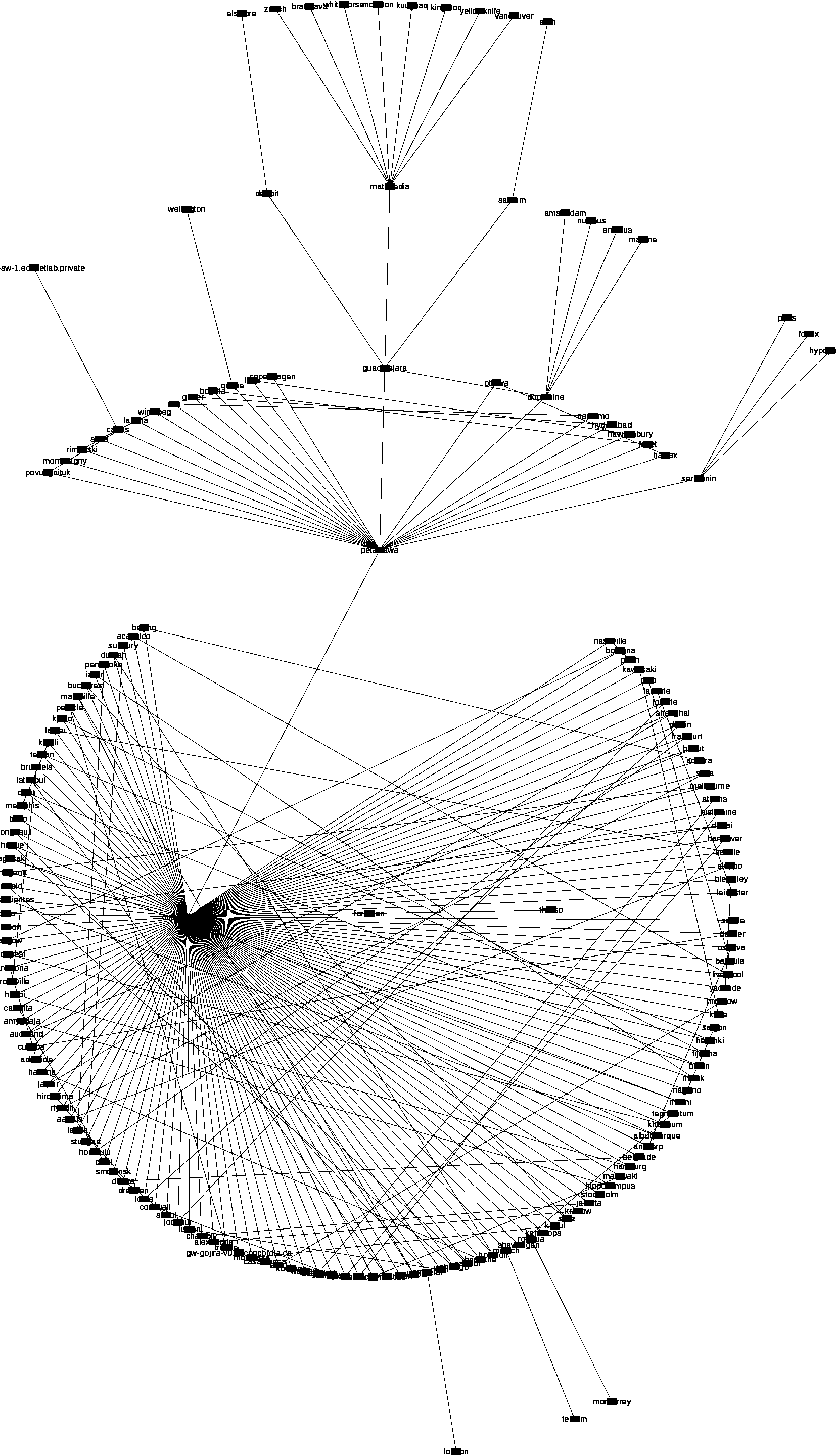
Scalability is an issue. During the course of the network’s evolution, we went from a few hundred computers and terminals running at 10 Mbps to a few thousand at 100 Mbps, and a few dozen at 1 Gbps. At present, downtime is approximately 30 seconds per month (excepting individual switch failures) for monthly maintenance. Delegating some network management responsibilities to the service desk and desktop group alleviates the burden via custom build scripts. We employed OSS tools that help us with that as well and are in the process of adopting Netdisco [18] with its web-based management console for the task to improve on that end further. Our overall topological perspective view of the switchfarm is illustrated in Figure 10 from Netdisco. The labels are intentionally obscured. We use MRTG [19, 17] as our graphing tool to visualise the traffic flows on switch ports.
0.6.1 Database
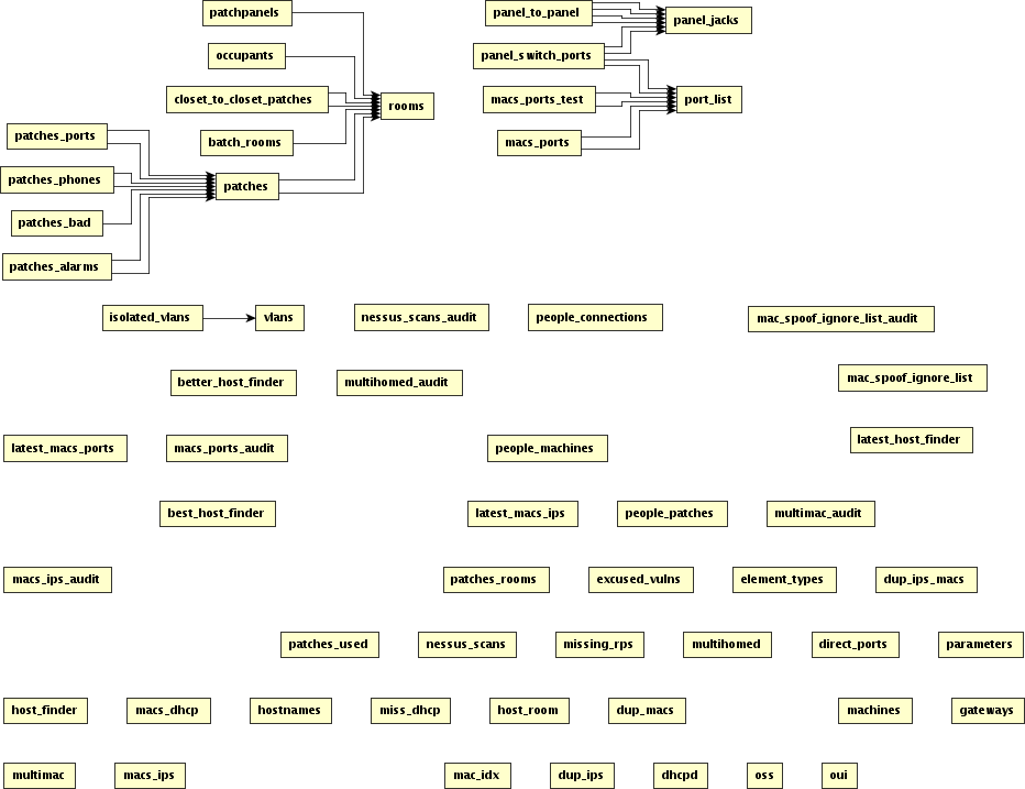
We designed our relatively large database using a PostgreSQL 8.x [37] setup to record the information of our switches, ports, patches, patch panels, jacks, rooms, room occupants, RP records for hosts, user-managed and analyst-managed, and the relationships between all those entities amounting at present to about 80 relations (tables, views, triggers, constraints). (See e.g. Figure 11). Some of the information is maintained by scripts, such as what is connected where and last seen on a switch or an ARP table, list of VLANs from the VTP master, and the like. The responsible person (RP) data are maintained manually as well as when new switches are deployed or relocated and new jacks, patches, and ports are added. A number of views (the largely single rectangles on the image) and interface scripts exists that allow the networking group and sister groups to query some of the data to perform their job, specifically by the service desk and the desktop groups for location awareness and default services, among others.
0.6.2 Scripting and automation
We have developed and continue developing, maintaining, refactoring what we call our scriptfarm for the management of the switchfarm, firewalls, the database, the switch logs, etc. The scripts also provide shells to other analysts in sister groups to access the network data and in some cases change it for us to scale. The majority of the scripts are written in Perl primarily for its powerful regular expressions [12], set of libraries for network and database programming [31], system administration [6] and for using Perl modules and objects [26]. For some scripting we reply on Python [7], in particular for our Snort customizations, as well as shell scripts in tcsh and bash.
We maintain an SCM repository (CVS [4]), and central Makefile-based [30] build and deploy system, and the startup scripts we need to uniformly use on our managed servers. Upon committing the revisions to the CVS the rest of the members are notified. The updates are propagated through the CVS as well to the server machines. The central consolidated repository for the all the numerous scripts in the scriptfarm significantly improves maintenance and accounting of the scripts and code auditing, and overall design and development process.
The automation aspect comes around maintaining the database about the current
state of the network as well as maintenance of the description fields on the
switch ports with a special [Auto] token set to make them more
usable and readable when viewing via MRTG
[19]
and other views and shells.
The automation of course covers security alerts to either mailing lists, individuals,
or the RT ticketing system if something noteworthy happens for us to take action.
Switch configuration backup is also part of the scriptfarm.
We also build our startup init scripts, typically launched from
different run levels when the machine boots depending on which
cron job and other services are assigned to a particular machine
at the boot time rather than to its back up peer.
0.7 Conclusion
We serve four different buildings with a network segregated by VLANs. Our switching design uses the spanning tree protocol with redundancy. Likewise we have redundant routing and firewalling geographically spread. We maintain a centralised DNS and DHCP. We support “multicast” ghosting (not true multicasting just yet, but rather broadcasting where the ghost data are transferred to every trunk). We maintain in-house and employ external OSS management software and a database that controls network data in a bidirectional manner. Various security scripts in the scriptfarm alert of problems.
Faced with IP address exhaustion we now have a motivational drive to move to IPv6. Managing excessive aggregate bandwidth is becoming a problem. Aging access layer and management software is another issue we are facing. Some new challenges emerge when building reorganizations take place. By the nature of our work we will be collaborating with the other networking groups beyond our faculty (e.g. access support for licensing, wireless, and others), whose topology design is significantly different from ours driving us to simplify operations. We are also dealing with issues regarding increasing service requests, virtualisation support, and maintaining data quality in our database.
Based on our experience, the broad guideline that we arrive at is that it’s useful to think about ways to let one’s network evolve over time rather than to redesign it from scratch whenever new problems arise. Campus-wide VLANs implementation is of particular mention. We also proposed ways of using old ideas and old solutions to existing and new problems. The rest can be derived from our report and adapted accordingly if needed for various aspects presented.
0.7.1 Statistics
-
•
4 buildings served
-
•
about 170 Catalyst 2950, 10 Catalyst 2960, 10 Catalyst 2970, 10 Catalyst 2924, 10 Catalyst 3550, 10 Catalyst 3548 switches
-
•
about 65 wiring closets
-
•
about 4800 clients
-
•
about 5800 patched jacks
-
•
about 200 VLANs
-
•
about 60 scripts in the scriptfarm
-
•
about 80 database relations (tables, views, triggers, etc.)
-
•
about 730 firewall rules on the internal edge; 450 firewall rules on the external edge
-
•
network group members ranged between 2 and 4 (presently) in charge of the network in the Faculty.
0.7.2 Future work
As we are moving towards newer hardware and tools and overall design, we are documenting the change and plan on reporting an updated experience report as a result. In summary, the future work in various terms and durations will focus on:
- 1.
- 2.
-
3.
Layers 2 and 3 switching / routing with eventual switchover of the internal router/firewall to the Cisco Catalyst 4510 and Catalyst 3750X switches.
-
4.
Cisco ACLs to reduce/eliminate Linux internal routers’ iptables load. To achieve that our ongoing preliminary plan is to simplify, consolidate, and eliminate some of the complexity of the current ruleset before actually moving onto the ACLs.
-
5.
Consolidate scripting with standardization and refactoring.
-
6.
Cloud/mobility/ubiquity support of various networking equipment.
-
7.
Network preparation for Active Directory (AD) service.
-
8.
Explore the OpenNMS [36] for a variety of management tasks in addition to our existing toolset.
Acknowledgment
This work is supported by the Faculty of Engineering and Computer Science, Concordia University, Montreal, QC, Canada. We acknowledge the feedback, bug reports, and suggestions from our sister IT groups of System Administration Group, Desktop Operations Group, User Services Group, Faculty Information Systems group, techies, and other colleagues.
References
- [1] Paul Albitz and Cricket Liu. DNS and BIND. O’Reilly, 3 edition, 1998. ISBN: 1-56592-512-2.
- [2] Richard Bejtlich. The Tao of Network Security: Beyond Intrusion Detection. Addison-Wesley, 2005. ISBN: 0-321-24677-2.
- [3] Anne Bennett and Michael J. Assels. Computer security at Concordia: Past problems, proposed plans. [online], 1995. http://alcor.concordia.ca/nonalcor/ssg/contributions/security-report/main.html.
- [4] Brian Berliner, david d ‘zoo’ zuhn, Jeff Polk, Larry Jones, Derek Robert Price, Mark D. Baushke, et al. Concurrent Versions System (CVS). [online], 1989–2011. http://savannah.nongnu.org/projects/cvs/.
- [5] Marc Blanchet. Migrating to IPv6: A Practical Guide to Implementing IPv6 in Mobile and Fixed Networks. John Wiley & Sons Ltd., 2006. ISBN: 978-0471-49892-6, http://www.ipv6book.ca/.
- [6] David N. Blank-Edelman. Perl for System Administration. O’Reilly, 2000. ISBN: 1-56592-609-9.
- [7] Wesley J. Chun. Core Python Programming. Pearson Education, Inc., 2 edition, 2007. ISBN: 1-56592-609-9.
- [8] Cisco. Spanning tree protocol (STP). [online], 2011. http://www.cisco.com/en/US/tech/tk389/tk621/tsd_technology_support_protocol_home.html/.
- [9] Cisco Systems, Inc. Catalyst 2950 Switch Hardware Installation Guide, October 2003.
- [10] Kennedy Clark and Kevin Hamilton. Cisco LAN Switching. Cisco Press, 1999. ISBN: 1-57870-094-9.
- [11] Sheila Frankel, Richard Graveman, John Pearce, and Mark Rooks. Guidelines for the secure deployment of IPv6. Technical Report Special Publication 800-119, NIST, December 2010. http://csrc.nist.gov/publications/nistpubs/800-119/sp800-119.pdf.
- [12] Jeffrey E. F. Friedl. Mastering Regular Expression: Powerful Techniques for Perl and Other Tools. O’Reilly, 1997. ISBN: 1-56592-257-3.
- [13] Eric Gamess and Neudith Morales. Implementing IPv6 at Central University of Venezuela. In Proceedings of the 4th international IFIP/ACM Latin American conference on Networking (LANC’07), pages 43–51, New York, NY, USA, 2007. ACM.
- [14] Craig Hunt. TCP/IP Network Administration. O’Reilly, 1993. ISBN: 0-937175-82-X.
- [15] Leszek Lilien, Adawia Al-Alawneh, and Lotfi Ben Othmane. The pervasive trust foundation for security in next generation networks. In NSPW’10, pages 129–141. ACM, September 2010. A Position Paper.
- [16] Thomas A. Limoncelli and Christine Hogan. The Practice of System and Network Administration. Addison-Wesley, 2002. ISBN: 0-201-70271-1.
- [17] Douglas R. Mauro and Kevin J. Schmidt. Essential SNMP. O’Reilly, 2001. ISBN: 0-596-00020-00.
- [18] Eric Miller, Bill Fenner, Oliver Gorwits, Jeroen van Ingen, Max Baker, and the Netdisco Community. NETDISCO – network management tool. [online], 2009–2011. http://netdisco.org/.
- [19] Tobi Oetiker, Dave Rand, and the MRTG Community. Tobi oetiker’s MRTG – the Multi Router Traffic Grapher. [online], 2008–2011. http://oss.oetiker.ch/mrtg/.
- [20] Radia Perlman. An algorithm for distributed computation of a spanning tree in an extended lan. SIGCOMM Comput. Commun. Rev., 15:44–53, September 1985.
- [21] Gregor N. Purdy. Linux iptables: Pocket Reference. O’Reilly, 2004. ISBN: 978-0-596-00569-6.
- [22] QoSient, LLC. Argus: Auditing network activity. [online], 2000–2011. http://www.qosient.com/argus/.
- [23] Michael Rash. Linux Firwalls: Attack Detection and Response with iptables, psad, and fwsnort. No Starch Press, Inc., San Francisco, 3 edition, 2007. ISBN: 978-1-59327-141-1.
- [24] Aviel D. Rubin. White-hat Security Arsenal: Tackling the Threats. Addison-Wesley Longman Ltd., Essex, UK, 2001.
- [25] Carla Schroder. Linux Networking Cookbook. O’Reilly, 2008. ISBN: 978-0-596-10248-7.
- [26] Randal L. Schwartz and Tom Phoenix. Learning Perl Objects, References and Modules. O’Reilly, 2003. ISBN: 0-596-00478-8.
- [27] Jordan Sissel. Making iptables changes atomically and not dropping packets. [online], March 2010. http://www.semicomplete.com/blog/geekery/atomic-iptables-changes-and-not-dropping-packets.html.
- [28] Sourcefire. Snort: Open-source network intrusion prevention and detection system (IDS/IPS). [online], 2010. http://www.snort.org/.
- [29] William Stallings. SNMP, SNMPv2, SNMPv3, and RMON 1 and 2. Addison-Wesley, 3 edition, 1999. ISBN: 0-201-48534-6.
- [30] Richard Stallman, Roland McGrath, Paul Smith, and the GNU Project. GNU Make. Free Software Foundation, Inc., [online], 1997–2006. http://www.gnu.org/software/make/.
- [31] Lincoln D. Stein. Network Programming with Perl. Addison-Wesley, 2001. ISBN: 0-201-61571-1.
- [32] Mani Subramanian. Network Management: Principles and Practice. Addison-Wesley, 2000. ISBN: 0-201-35742-9.
- [33] Steve Suehring and Robert L. Ziegler. Linux Firwalls. Pearson Education, Inc. and Novell Press, 3 edition, 2006. ISBN: 978-0-672-32771-1.
- [34] Tenable Network Security. Nessus: the network vulnerability scanner. [online], 2002–2011. http://www.nessus.org/nessus/.
- [35] The IPv6 Experts. The IPv6 experts .net: Your black and white guide to the new internet. [online], 2010. http://www.theipv6experts.net.
- [36] The OpenNMS Community. The OpenNMS project. [online], 1999–2011. http://www.opennms.org/.
- [37] The PostgreSQL Global Development Group. PostgreSQL – the world’s most advanced open-source database. [ditigal], 1996–2011. http://www.postgresql.org/, last viewed January 2010.
- [38] Wikipedia. Spanning tree protocol — Wikipedia, the free encyclopedia, 2010. [online; accessed 13-December-2010], http://en.wikipedia.org/w/index.php?title=Spanning_tree_protocol&oldid=397364209.
Index
- 802.1X §0.4
- API
- ARP §0.6, §0.6.1
-
database 2nd item, §0.1.2, §0.4, §0.4, §0.5.4, §0.6.1, §0.6.1, §0.6.2
- PostgreSQL §0.6.1
- firewall 5th item, §0.2.3, §0.3, §0.5.1, §0.5.1, §0.5.1, §0.5.5, §0.6.2, 9th item, item 3, §0.7
- ghosting 5th item, 1st item, §0.1.2, §0.2.3, §0.2.3, §0.5.3, §0.7
- IPv6 item 2, §0.7
- logging §0.2.1, §0.5.1
- monitoring 2nd item, §0.2.1, §0.5.1
- multicast 1st item, §0.7
- NAT §0.2.3, §0.5.1, §0.5.1
- Protocols
- routing §0.1.4, §0.2.3, §0.3, §0.3, §0.5, §0.5.1, §0.5.1, item 3, §0.7
- scalability 2nd item, §0.1.1, §0.4, §0.5.2, §0.6
- scriptfarm §0.5.4, §0.6.2, §0.6.2, §0.6.2, 7th item, §0.7
- scripting 2nd item
- security 1st item, §0.1.1, §0.1.4, §0.4, §0.4, §0.5, §0.5.1, §0.6.2, §0.7
- services §0.1.4, §0.2.3, §0.4, §0.4, §0.4, §0.5, §0.5.1, §0.5.1, §0.5.1, §0.5.2, §0.6.1, §0.6.2
- SNMP §0.6
- spanning tree 3rd item, §0.1.4, §0.2.1, §0.2.2, §0.2.2, §0.2.2, §0.7
- Switches
- switchfarm Figure 10, §0.1.4, §0.2, §0.2.3, §0.3, §0.6, §0.6.2
- Tools
- VLAN