Bounce-free Spherical Hydrodynamic Implosion
Abstract
In a bounce-free spherical hydrodynamic implosion, the post-stagnation hot core plasma does not expand against the imploding flow. Such an implosion scheme has the advantage of improving the dwell time of the burning fuel, resulting in a higher fusion burn-up fraction. The existence of bounce-free spherical implosions is demonstrated by explicitly constructing a family of self-similar solutions to the spherically symmetric ideal hydrodynamic equations. When applied to a specific example of plasma liner driven magneto-inertial fusion, the bounce-free solution is found to produce at least a factor of four improvement in dwell time and fusion energy gain.
pacs:
52.58.Qv, 52.35.Tc, 52.50.Lp, 52.25.XzSpherical hydrodynamic implosion is a central concept in inertial confinement fusion (ICF) Lindl and magneto-inertial fusion (MIF) Lindemuth , which use a variety of inertial pushers driven by lasers Atzeni , heavy ion beams heavy_ion , and pulsed power Intrator . It is also of fundamental importance in late-stage stellar evolution, especially supernova core collapse Bethe . In a typical spherical hydrodynamic implosion, converging mass flow provides compressional (and possibly shock) heating of the core, converting flow kinetic energy into thermal energy of the plasma localized about the center of symmetry. Once the peak pressure is reached, a stagnation surface appears between the core and imploding flow plasmas. What happens next is usually a bounce motion of the core in which the hotter plasma at the center expands against the imploding flow. In the special case where the interface between the hot core and imploding flow remains stationary rather than expanding outward, one has a bounce-free spherical hydrodynamic implosion. That is, while in the typical bounce case both the core/pusher interface and stagnation surface move radially outward, in the bounce-free case the core/pusher interface remains stationary and only the stagnation surface moves radially outward. In either case, once the stagnation surface sweeps through the entire imploding material, the whole core-pusher assembly will undergo an expansion. The latter imposes an upper limit on the system dwell time.
Optimizing toward a bounce-free implosion provides the most design freedom in increasing the dwell time and thereby a higher fusion burn-up fraction, which as shown in this Letter, can be achieved by employing a specially shaped pusher. This approach is most naturally applied and would be of most benefit to plasma liner driven MIF thio since there the pusher (liner) is created by merging plasma jets conceptually capable of modulating the imploding flow profile. Also, due to the challenge for MIF to attain an ignited burn wave, it has the greatest need for increasing the burn fraction via increased dwell time. Conversely, the lack of a strong burn wave and intense hot spot pressures might actually make the bounce-free implosion scheme energetically feasible to implement.
In this Letter we present a family of self-similar solutions to the spherically symmetric ideal hydrodynamic equations which produce bounce-free spherical implosions. The physics implications of these bounce-free implosion solutions are explained in the application to plasma liner driven MIF. In particular, we find that by maintaining a bounce-free implosion through liner (inertial pusher) profile shaping, the dwell time of the compressed hot fuel can be improved by at least a factor of four compared with a specific example of a stationary liner profile parks-pop-2008 , while holding the liner speed and total energy the same.
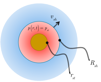
To motivate the analytical solution, we first outline the physical picture of and the mathematical constraints on bounce-free spherical hydrodynamic implosions. Figure 1 shows a sketch of the assembly after the liner hits the target. The stagnation or ignition pressure of the target is achieved at time with the spherical interface between the hot spot and the liner at coming to rest. To be bounce-free, this interface remains still for This is made possible by shock heating of the liner plasma neighboring In other words, a shock arises at the interface at and propagates radially outward. The shocked liner in the region of is in static pressure balance with the target, The shock front at becomes a second stagnation surface, which along with the interface at , bounds an ever-expanding, stagnated, and shock-heated liner. The imploding liner for such a bounce-free regime must have highly constrained profiles of density , pressure , and flow speed .
This Letter demonstrates the existence of bounce-free spherical implosions by presenting a family of imploding flow solutions that exactly satisfy the hydrodynamic equations and jump conditions at as well as the following constraint
| (1) |
for and Interestingly, such a solution consistently describes cases of both an infinitesimally small target (void) and a finite sized target kept still. Indeed, the liner flow solution with no distinct target satisfying Eq. (1) obeys all the first principle equations even upon ”inserting” the target into the center of symmetry, while condition of the shocked liner pressure being constant ensures that the target stays at rest. We notice that the solution we are aiming for is thus a generalization of a well known Noh’s solution Noh . Indeed, Noh’s solution gives the uniform pressure and density in the stagnated gas for the case, in which the initial converging shell, and therefore the the unshocked part of the liner as sketched in Figure 1, is perfectly cold, while the solution to be presented here allows temperature of the shell to be finite. Unlike Noh’s case, it is then not possible to write a simple analytical formula describing liner evolution. It is still possible though to reduce the problem to a set of relatively simple ordinary differential equations, as we demonstrate later in this Letter.
The simplest model for spherically symmetric ideal hydrodynamic implosion is the conservation laws for fluid mass, momentum, and entropy
| (2) | |||||
| (3) | |||||
| (4) |
where the subscripts “t” and “r’ denote differentiating over the time and radial variables, respectively. These three equations need to be solved in the unshocked region of the liner with the jump condition at the shock front connecting the infalling liner to the bounce-free constraints, Eq. (1). To this end, it is convenient to focus our consideration on the similarity solutions. A large class of such solutions and their application to ICF problems is considered in Ref. Atzeni . In our case, its sub-class, the so-called spherical quasi-simple waves, turns out to be sufficient. To relate these waves to those described in Ref. Atzeni , one should start from the more general form given by its Eqs. (6.182-6.183) and set and . In the next paragraphs we follow §§162-164 of Ref. courant-book-1976 to outline the basic features of this solution family which we then utilize for the purpose of this Letter.
Spherical flow belongs to the class of quasi-simple waves if the velocity, pressure, and density are constant on rays An immediate consequence of this property is that the flow is isentropic, i.e., is not only conserved for a given fluid element, as guaranteed by Eq. (4), but is also the same for all fluid elements. The pressure and density can be then expressed in terms of the sound speed and with the help of some algebraic manipulations, Eq. (2) and (3) reduce to
| (5) | |||||
| (6) |
where and To write Eqs. (5,6), pressure, density, velocity, the radial coordinate and time are normalized to , and , respectively.
It is instructive to consider possible scenarios on the plane. To do so we divide Eq. (6) by Eq. (5) to find
| (7) |
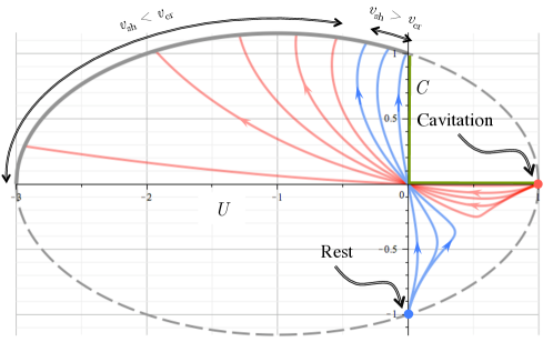
The full vector field of Eq. (7) is quite complex and contains a number of different regimes (e.g., see Fig. 11 of Ch. 6 of Ref. courant-book-1976 ). The trajectories of interest (i.e., those corresponding to the converging flow stopped by the shock wave propagating outward) are located in the upper-left quadrant of the plane, as plotted in Fig. 2. The arrows are in the direction of growing i.e., the direction of growing for fixed or decreasing for fixed
The jump conditions along with Eq. (1) can be employed to find that and values of and just before the shock front, must obey
| (8) | |||||
| (9) |
where is the shock speed and Eq. (8) implies that the shock transition takes place on an ellipse in the plane. Choosing a certain point on this ellipse then gives the shock speed through Eq. (9). Hence, the desired regime is described by a curve uniquely defined by that starts somewhere on the ellipse in the upper-left quadrant and runs toward the origin of the plane, since this direction corresponds to going to larger radii for a fixed Importantly, and tend to zero together with so that the sound speed and the fluid velocity stay finite. For a given curve, and as functions of can be found by integrating Eqs. (8,9) from to with initial conditions and where Once and are evaluated, and can be recovered from definitions given after Eq. (6), and and can be found from the isentropicity condition. As a result, we obtain a solution family parameterized by for bounce-free spherical imploding flows.
Any set of profiles and generated as described in the preceding paragraph explicitly answers the question of what the liner profiles must be at and after stagnation in order for the target to maintain constant pressure and remain bounce-free. Next, we investigate the evolution of the liner prior to stagnation to see whether the liner profile found can be created in a practical device. To do so, we need to solve Eq. (6,5) backward in time, i.e., extend the previously found solution from the upper-left quadrant of Fig. 2 to the lower-right one. In physical space, passing through the origin of Fig. 2 corresponds to the liner reaching the center of symmetry. Consequently, unlike the previously considered post-stagnation solutions, this part of our analysis (for ) only qualitatively applies to the physical case of a finite-size, preformed target. Nevertheless, even such a qualitative consideration provides substantial insight into relevant liner parameters, as we demonstrate next.
As shown in Fig. 2, a critical point exists on the ellipse such that for the solution curve ends up in the “rest point” (), whereas for in the “cavitation point” (). The former case corresponds to the situation in which initially the entire space beyond the stagnation radius is occupied by a liner material at rest with finite density and pressure. The latter case corresponds to the situation in which initially there is a vacuum between the infalling liner material and the target. This is the default regime for a plasma liner driven MIF experiment. Despite behavior of all the curves being qualitatively the same for only those generated from shall therefore be considered. To show the characteristic liner evolution in the cavitation regime we set and integrate the fluid equations as previously described to obtain and Then, by inserting for we generate a series of snapshots to create an animation animation of pre- and post-stagnation phases of a bounce-free spherical implosion.
Having now proven the existence of bounce-free spherical hydrodynamic implosion by explicitly constructing a family of self-similar solutions to the spherically symmetric hydrodynamic equations, our next objective is to elucidate the physics implications of this regime. As previously mentioned, the physics advantages of bounce-free implosion is probably most easily appreciated in the plasma liner driven MIF concept. This is for two reasons. The first is that generally MIF schemes do not rely on an ignited burn wave because they operate at ignition densities substantially lower than for ICF; the desired high burn fraction is primarily achieved by maintaining the compressed hot spot at thermonuclear burning condition for as long as possible. A bounce-free implosion minimizes the decompressional cooling of the target compared with a normal bounced implosion. The second is that by employing a standoff driver such as an array of plasma guns to form and deliver the liner, one has substantial freedom in shaping the liner profile (density, speed, and thermal pressure) and the possibility of using a thick, as opposed to thin, liner. It is also of interest to note that because of the much smaller areal density of MIF targets, compared with that of conventional ICF, the mean free path of an alpha particle is much greater than the target radius and neglecting fusion heating effect on the target pressure and on the right side of Eq. (4) is a useful approximation. Next, we illustrate the potential energy gain by comparing the dwell time estimate of the bounce-free implosion solution with an example of a conventional implosion.
Discussion on which of the curves with would work best for a realistic plasma liner MIF device is beyond the scope of this Letter and will be presented elsewhere. In what follows, we focus on the general effect of liner shaping toward bounce-free implosion to demonstrate that employing a solution presented here can result in a substantial dwell time improvement. To do so, it is convenient to take the estimate of Ref. parks-pop-2008 , where no special liner shaping is assumed and a simple stationary flow solution is used to model the liner profiles, as a reference point. Namely, we next consider a liner of the newly found form whose energy and velocity, as well as the relevant target parameters, are the same as in Ref. parks-pop-2008 . It is then reasonable to attribute the difference between the dwell time predictions to that between the liner shapes and, accordingly, whether or not the implosion results in target bounce.
The earlier estimate parks-pop-2008 assumes that a target expands (bounces) at a speed as fast as the shock front propagation for and the fuel disassembly is considered to be complete once its radius becomes as given in Eq. (38) of Ref. parks-pop-2008 . The dwell time is therefore obtained by computing where is 0.5 cm. The shock speed is estimated to be half of the 100 km/s liner velocity and is thus 50 km/s. As a result, the dwell time estimate is 100 ns. The target temperature is taken to be 10 keV, with a fuel burn-up fraction of about 0.01, and the corresponding stagnation pressure is 62.5 Mb. The total liner kinetic energy is 122 MJ and the fusion energy gain factor is estimated to be about 2.6%. We now proceed by conducting a similar estimate for the bounce-free liner solution.
If it were possible to maintain the unshocked liner flow with the prescribed profiles infinitely long, the target would never bounce and be forever kept in a state of maximum compression. Practically, the total liner energy is finite and we need to “cut” the liner profile at a certain point to match the above-mentioned 122 MJ total liner energy constraint. Of course, such cutting of a fluid equation solution results in a rarefaction wave spreading beyond the outer boundary of the liner. However, until a moment when the shock wave hits the outer boundary of the liner, this rarefaction wave propagates at the unshocked liner sound speed, which is generally much less than the speed of the liner itself. It is therefore a good approximation that despite being finite the liner evolves in space and time according to the exact solution above for At the entire liner is shocked and the rarefaction wave is no longer negligible, since the shocked liner sound speed is comparable to Once the rarefaction wave hits the target, it finally starts disassembling. Accordingly, the dwell time can be estimated by
| (10) |
where is the time it takes the rarefaction wave to travel from the outer liner boundary position at to Note that we are neglecting the further finite time it would take for the target to double its radius, which is the criterion for dwell time used in Ref. parks-pop-2008 . Thus, our estimate, Eq. (10), is a conservative one.
To evaluate the first term on the right hand side of Eq. (10) we note that where can be calculated from liner energy conservation since the hydrodynamic efficiency of the target compression is low parks-pop-2008 ; cassibry-pop-2009 . That is,
| (11) |
where we have used the fact that the energy density of the shocked liner is equal to and stands for the total liner energy. It should be noted that Eq. (11) gives , making our estimate quite insensitive to uncertainties in . To isolate the effect of bounce-free liner shaping, we insert into Eq. (11) the same values of 62.5 Mb, 0.5 cm, and 122 MJ for and as in Ref. parks-pop-2008 . Eq. (11) then gives and, upon setting the liner and shock front velocities 100 km/s and 50 km/s to match those of Ref. parks-pop-2008 , we find ns.
The second term on the right hand side of Eq. (10) can be estimated by noticing that the rarefaction wave propagates at where, as in the preceding paragraph, we set km/s. It then takes about ns for the rarefaction wave to reach the target and Eq. (10) gives ns, which is four times larger than its counterpart in the bounced implosion. Since the target parameters are chosen to be the same, the fusion energy gain factor is four times larger as well (even neglecting the target radius doubling time in the bounce-free case).
In conclusion, we have demonstrated that by shaping the profiles of an imploding inertial pusher, the concept of bounce-free spherical hydrodynamic implosion can be physically realized. A family of self-similar bounce-free solutions to the spherically symmetric ideal hydrodynamic equations is explicitly found, along with a description of their experimental accessibility. For the specific application of plasma liner driven MIF, we show that using bounce-free liner profiles can substantially slow down the core plasma expansion. As a result, the dwell time, and therefore the fusion gain, can be noticeably increased over an unshaped liner with equivalent kinetic energy. Compared to the specific case treated in Ref. parks-pop-2008 , employing the bounce-free implosion regime improves the dwell time and energy gain by at least a factor of four. Furthermore, the newly found implosion regime supports the idea of using deuterium-tritium fuel in the inner parts of the liner (as suggested in Ref. thio and Ref. Lindemuth ), which upon becoming shocked will also burn, thus further increasing the gain. Indeed, in such a regime, the post-shocked liner is at rest, i.e., in contrast to previously considered schemes, the kinetic energy of the original liner is entirely converted into internal energy. This feature brings the temperature of the liner next to the target closer to fusion relevant magnitudes, which may further improve the overall efficiency of plasma liner driven MIF devices.
This work was supported by the Laboratory Directed Research and Development (LDRD) program of LANL (Kagan and Tang) and the U.S. Department of Energy Office of Fusion Energy Sciences under contract DE-AC52-06NA25396 (Hsu and Awe).
References
- (1) J. D. Lindl et al, Phys. Plasmas 11, 339 (2004)
- (2) R. C. Lindemuth and I. R. Kirkpatrick, Nucl. Fusion 23, 263 (1983).
- (3) S. Atzeni and J. Meyer-ter-Vehn ”The Physics of Inertial Fusion”, Clarendon Press - Oxford (2004).
- (4) J. Meyer-ter-Vehn, Plasma Phys. Control. Fusion 31, 1613 (1989).
- (5) J. H. Degnan et al, Phys. Rev. Lett. 82, 2681 (1999).
- (6) H. A. Bethe, Rev. Mod. Phys. 62, 801 (1990).
- (7) Y. C. F. Thio et al, “Magnetized target fusion in a spherical geometry with standoff drivers” Current Trend in International Fusion Research – Proc. 2nd International Symposium, E. Panarella, ed. (NRC Canada, Ottawa, 1999).
- (8) P. B. Parks, Phys. Plasmas 15, 062506 (2008).
- (9) W. F. Noh, J. Comp. Phys. 72, 78 (1987).
- (10) R. Courant and K. O. Friedrichs, “Supersonic Flow and Shock Waves” Springer, Berlin (1976).
- (11) liner_evolution.gif (attached).
- (12) J. T. Cassibry et al, Phys. Plasmas 16, 112707 (2009).