Single-step implementation of the controlled-Z gate in a qubit/bus/qubit device
Abstract
We propose a simple scheme for generating a high-fidelity controlled-Z (CZ) gate in a three-component qubit/bus/qubit device. The corresponding tune/detune pulse is single-step, with a near-resonant constant undershoot between the and states. During the pulse, the frequency of the first qubit is kept fixed, while the frequency of the second qubit is varied in such a way as to bring the and states close to resonance. As a result, the phase of the state is accumulated via the corresponding second-order anticrossing. For experimentally realistic qubit frequencies and a 75 MHz coupling (150 MHz splitting), a 45 ns gate time can be realized with % intrinsic fidelity, with errors arising due to the non-adiabaticity of the ramps. The CZ pulse is characterized by two adjustable parameters: the undershoot magnitude and undershoot duration. The pulse does not load an excitation into the bus. This by-passes the previously proposed need for two additional qubit-to-bus and bus-to-qubit MOVE operations. Combined with the recently predicted high-fidelity idling operation in the RezQu architecture [A. Galiautdinov, J. Martinis, A. Korotkov (unpublished)], this controlled-Z scheme may prove useful for implementations on the first generation quantum computers.
pacs:
03.67.Lx, 85.25.-jI introduction
Recent progress in preparing, controlling, and measuring the macroscopic quantum states of superconducting circuits with Josephson junctions YAMAMOTO2003 ; STEFFEN2006 ; PLANTENBERG2007 ; NEELEY2008 ; DICARLO2009 ; BIALCZAK2010 ; REED2010 makes realization of a quantum computer an experimental possibility CLARKE2008 . Two major roadblocks – decoherence and scalability – may soon be overcome by the so-called Resonator/zero-Qubit (RezQu) architecture, recently proposed by J. Martinis RezQu . Some of the basic operations of the RezQu architecture (such as the idling operation, the generation and measurement of the single-excitation states, as well as the single-excitation transfer operation called MOVE) were analyzed in a joint paper IDLING-PAPER . It was found, that the RezQu architecture is capable of providing high-fidelity performance required for quantum information processing.
In spite of the optimistic conclusions presented in Ref. IDLING-PAPER , an important problem of generating high-fidelity entangling operations in the RezQu architecture still remains. One such operation is the controlled-Z (CZ) gate, given in Eq. (8). It is believed that, in the RezQu architecture, the CZ gate may easily be produced using the SWAP-based three-step approach, similar to that of Ref. Haack-2010 , in which one logic qubit is moved to the bus, transferring the qubit excitation onto the bus, while the other qubit is tuned close to resonance with the bus for a precise duration. After the needed phase is accumulated (as in Refs. Strauch-2003 ; Yamamoto-10 ), the excitation is moved back from the bus to the original qubit. We have simulated this three-step approach for realistic RezQu parameters and found some difficulties with it, which are described in Section III. This prompted us to look for a more direct scheme, which is not beset by such difficulties. The scheme is described in Sec. V. It does not rely on the loading and unloading of the bus, but instead, uses a second order anticrossing for the required phase accumulation (cf. Ref. Zheng-2009 ).
II The qubit/bus/qubit device
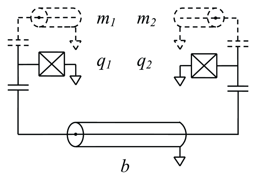
A three-component RezQu device is depicted in Fig. 1. In the rotating wave approximation (RWA), its dynamics is described by the Hamiltonian
| (1) |
where
| (2) |
are the Hamiltonians of the qubits whose frequencies may vary in time and the anharmonicities are assumed to be constant,
| (3) |
are the qubit lowering and raising operators, is the bus frequency (which is held fixed), and are the creation and annihilation operators for the bus photons, and , are the bus-qubit coupling constants. In our numerical simulations we will assume that and .
III Some difficulties with the SWAP-based controlled-Z gate implementation
| Bare | Before and | Optimized CZ frequencies at |
|---|---|---|
| frequencies | after CZ | the anticrossing |
| 6.6 | 6.6 | |
| 6.0 | 6.0 | |
| 6.5 | 6.40959 | |
| 12.6 | 12.6 | |
| 13.1 | 13.00959 | |
| 12.5 | 12.40959 | |
| 13.0 | 13.0 | |
| 12.0 | 12.0 | |
| 12.8 | 12.61918 |
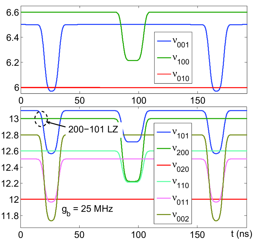
In what follows, we assume that the qubit/bus/qubit system starts and ends in the (default) configuration, as shown in Table 1. The initial and final qubit frequencies, , are chosen in such a way as to avoid the and crossings. Then, the standard Yamamoto-10 three-step SWAP-based CZ gate implementation (Fig. 2) suffers from the following major drawback: it produces a large number of Landau-Zener (LZ) transitions, each of which degrades the resulting gate’s fidelity. The RezQu architecture based on fixed couplings may not be flexible enough to provide the needed controllability to counter the effects of all these transitions in a three-step CZ manner. Controlling only the qubit frequencies may not be enough to achieve the needed accuracy of the CZ gate, using experimentally reasonable number of parameters. As Fig. 2 shows, the very first ramp of the initial SWAP operation already contains one such LZ crossing, leading to the leakage from state to state .
Here we propose to turn this particular drawback into an asset by dropping the loading and unloading SWAP operations altogether and employing the mentioned anticrossing to accumulate the needed 101-phase during the CZ operation (see Fig. 3).
IV Potential problems with the proposed scheme
The following two problems may arise in our scheme.
First, the presence of additional system elements (qubits, memory resonators, etc.) may result in additional states that are near-resonant with the states and , thus leading to unwanted leakage. Here we ignore this complication and assume that under realistic conditions it will always be possible to isolate this particular anticrossing sufficiently well.
Second, being a second-order process, accumulation of the 101-phase may proceed too slowly compared with the qubit coherence time (currently at about ns). However, the following argument shows that this is not necessarily true.
In the case of a similar second order resonance , the effective (via the bus) - coupling Pinto-2010 is given by
| (4) |
Then in our case we should have
| (5) |
Choosing MHz (experimentally achievable coupling) and setting GHz (near-resonant condition), we find for GHz,
| (6) | |||||
which gives an experimentally reasonable duration of the corresponding phase accumulation,
| (7) |
In the actual implementation shown in Fig. 2, the total gate duration had to be prolonged to ns in order to correctly produce the final populations of and states.
V Implementing the single-step CZ gate
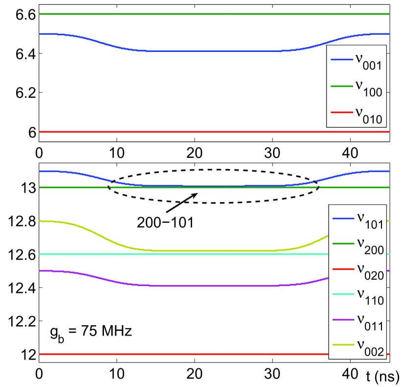
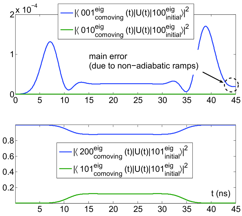
The proposed single-step CZ gate resulting from a two-parameter optimization with the RWA Hamiltonian of Eq. (II) is depicted in Fig. 3. To provide some intuitive understanding of how the generated gate works, the overlaps between the time-evolved logic states and some of the time-dependent (comoving) system eigenstates are given in Fig. 4.
Our gate is implemented in the computational basis consisting of the full system eigenstates IDLING-PAPER . It has the form
| (8) |
where and are some arbitrarily accumulated phases. Due to the use of the system eigenstates, these phases can always be adjusted simply by waiting. The optimization was performed at fixed ns by minimizing the function
| (9) | |||||
where
| (10) |
with respect to the undershoot magnitude and the undershoot duration (measured between the central points of the ramps), with additional constraints and . The widths (standard deviations) of the error-function-shaped ramps were held fixed at 3 ns. The results are presented in Fig. 3. In the above, is the unitary operator representing the CZ pulse, and the overbars stand for the prefix “eigen-.” The optimization function was defined so that for , as given in Eq. (8), . Notice, that we do not have to take into account the phase of the state, since the corresponding frequency can always be set to 0.
VI CZ gate as an idling error
Our CZ gate may be viewed as a particular example of an “idling error” IDLING-PAPER , which is a measure of how fast the phase of the computational eigenstatestate accumulates relative to the phases of eigenstates and . The error is characterized by the running frequency , with being the corresponding eigenenergies, and physically arises due to the level repulsion between 101 and other levels in the two-excitation subspace of the system. Consequently, a superposition of computational states evolves as
| (11) | |||||
and so, after a time , the state gets multiplied by -1. Thus, in systems with nonlinearities, the CZ gate can always be generated simply by waiting. For the qubit/bus/qubit RezQu device, using Eq. (II), we find in fourth order,
| (12) |
which for the above mentioned (and fixed) GHz and GHz, at coupling, produces the CZ gate after about 130 ns, which is too long. For a more efficient CZ generation, the system parameters must be set to maximize . One such choice, , which corresponds to the anticrossing, was made in our single-step implementation.
VII Conclusion
To summarize, we introduced a scheme for single-step generation of a high-fidelity controlled-Z gate in a three-component RezQu architecture. Despite the use of a second-order anticrossing, the accumulation of the needed 101-phase proceed sufficiently fast compared with the qubit coherence time. Different from the usually considered proposals, our CZ scheme does not rely on the MOVE operations transferring excitations to and from the bus. The resulting simplicity of the generated gate may prove useful for implementations in the first generation solid state quantum computers.
Acknowledgements.
This work was supported by NSA/IARPA/ARO Grant No. W911NF-10-1-0334.References
- (1) Y. Yamamoto et al, Nature 425, 941 (2003).
- (2) M. Steffen et al., Science 313, 1423 (2006).
- (3) J. H. Plantenberg et al., Nature 447, 836 (2007).
- (4) M. Neeley et al., Nature Physics 4, 523 (2008).
- (5) L. DiCarlo et al, Nature 460, 240 (2009).
- (6) R. C. Bialczak et al., Nature Physics 6, 409 (2010).
- (7) M. D. Reed et al., Phys. Rev. Lett. 105, 173601 (2010).
- (8) J. Clarke and F. K. Wilhelm, Nature 453, 1031 (2008).
- (9) J. M. Martinis (unpublished).
- (10) A. Galiautdinov, J. Martinis, A. Korotkov, presented at the 2011 APS March Meeting, Dallas, TX (unpublished).
- (11) R. A. Pinto et al., Phys. Rev. B 82, 104522 (2010).
- (12) G. Haack et al., Phys. Rev. B 82, 024514 (2010).
- (13) F. W. Strauch et al., Phys. Rev. Lett. 91, 167005 (2003).
- (14) T. Yamamoto et al., Phys. Rev. B 82, 184515 (2010).
- (15) Shi-Biao Zheng, Appl. Phys. Lett. 94, 154101 (2009).